Now that's a very good question. So its to do with getting high NFB. The plate resistors and capacitance of more stages add lag both at HF and LF (coupling caps). I am driving more load too (2x6550 and 47K). The combination seemed to me that a buffer stage was more appropriate. Like you I decided to use some SS anyway. The primary capacitance of the OPT is important to model as well as the leakage inductance, and I found that stability could become an issue. The aim was to maintain as much bandwidth as possible up to the OPT. There is more than one approach. What you have done looks good - my only comment would be you may need to add dominate pole into the design - I put this between the jfet gates as here it does not affect slew rate. You may also need some pole - zero cancellation to get the LF stable.
Last edited:
.png")
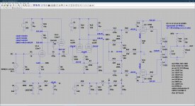
This was the previous amp, there was only just enough gain for the 18dB FB to work, but here the cascade is a pentode.
Now that's a very good question. So its to do with getting high NFB. The plate resistors and capacitance of more stages add lag both at HF and LF (coupling caps). I am driving more load too (2x6550 and 47K). The combination seemed to me that a buffer stage was more appropriate. Like you I decided to use some SS anyway.
I’ve simulated a similar approach, with cathode followers, which indeed allows me to get rid of one set of coupling caps, the THD goes up by a factor of 20x though, which seemed counterproductive to me, but we all need to make choices during the design, so I totally understand.
The primary capacitance of the OPT is important to model as well as the leakage inductance, and I found that stability could become an issue. The aim was to maintain as much bandwidth as possible up to the OPT. There is more than one approach. What you have done looks good - my only comment would be you may need to add dominate pole into the design - I put this between the jfet gates as here it does not affect slew rate. You may also need some pole - zero cancellation to get the LF stable.
Wholeheartedly agree, I should have the prototype finished by next week which will allow me to check and modify the simulation and work towards a design with the least amount of compromises. Suggestions are welcome by the way, even small tweaks left and right. Thanks!
If your getting sub .3% then don't forget LTSpice is using perfectly matched 12ax7. Its also possible to get distortion cancellation between different stages. So the design may look very good in LtSpice. You could try for example a 12ax7 on one side and a 5751 on the other for mismatch. Certainly the cathode follower with a E88CC should be pretty low distortion.
If your getting sub .3% then don't forget LTSpice is using perfectly matched 12ax7. Its also possible to get distortion cancellation between different stages. So the design may look very good in LtSpice. You could try for example a 12ax7 on one side and a 5751 on the other for mismatch. Certainly the cathode follower with a E88CC should be pretty low distortion.
Yes, of course, I lose a few zeros but the performance is still better than the version without the cascode. Also the CCS at the bottom does correct small differences between the two triodes both in the input stage and the intermediate stage.
To improve real life performance, you can add a trimmer between the cathodes of the 12ax7 and the ccs: you can balance them and add some local feedback to improve open loop THD.
To improve real life performance, you can add a trimmer between the cathodes of the 12ax7 and the ccs: you can balance them and add some local feedback to improve open loop THD.
Good suggestion, I was indeed planning on doing exactly that. If you have other tricks and/or tweaks please let me know as I’d love to try them, thanks!
P.s. I’m also looking for suggestions for an elegant, yet simple and effective, auto bias scheme, preferably using transistors rather than opamps.
.png")
.png")
REF is .4v reference when operating at startup -.6v. This make sure the grids remain negative until warmed up. The grid is driven through 100k resistor from GRID. The cathode is connected to CATH with a current setting resistor to ground. Current = .4v/Rset. Vpos is about 12v. Vneg about -70v.
REF is .4v reference when operating at startup -.6v. This make sure the grids remain negative until warmed up. The grid is driven through 100k resistor from GRID. The cathode is connected to CATH with a current setting resistor to ground. Current = .4v/Rset. Vpos is about 12v. Vneg about -70v.
Thanks, did you simulate startup behavior etc.?
Yep. Its also a built design. I also look at shutdown too to check there was no big thump which one amp had an issue.
Yep. Its also a built design. I also look at shutdown too to check there was no big thump which one amp had an issue.
Excellent, thanks again.
Happy simulation. The diode is there so that when you go from class A into class B the bias does not drift too much. There's no easy solution to this but in practice its fine. There's also bias boards you can buy on line. I have used these too but the one I had needed the negative rail to be hum free. The PNP needs to be 120V and reasonable Hfe at low current. Think I used a KSA1013 but would have to check.
Last edited:
Happy simulation. The diode is there so that when you go from class A into class B the bias does not drift too much. There's no easy solution to this but in practice its fine. There's also bias boards you can buy on line. I have used these too but the one I had needed the negative rail to be hum free. The PNP needs to be 120V and reasonable Hfe at low current.
Thanks, I wasn’t planning on buying a readymade solution, where’s the fun in that? 😀
You could always prototype one around a KT88 to test. The caps are both film. 4u7 @ 100V is quite big. The 10u is lower voltage. tants may work.
You could always prototype one around a KT88 to test.
Yes, that way it would be easy to track exactly what happens with a multichannel scope.
Let me check all the notes I took while playing with that circuit, I remember I did some tests on it. Play with the cascode reference voltage chasing best harmonics slope, not lowest thd.
I indeed tested also U440 to improve the pairing of the jfets: You can find 6n2p well matched from russian/ucrainian sellers.
I indeed tested also U440 to improve the pairing of the jfets: You can find 6n2p well matched from russian/ucrainian sellers.
- Home
- Amplifiers
- Tubes / Valves
- Cascoded 12AX7 LTP - Stupid good performance?