Hello everyone,
This is a non audio project strictly power.
The project : autonomously control a slot car. HO scale 1/64 to be exact.
I have a 5-30v 0-5a adjustable dc to dc pwm converter (it came from temu so spec's are Shecky at best ). I hacked the MOSFET circuit of the pwm controller and I am controlling it with an arduino to control the speed of the car. The arduino uses a signal from IR sensors to change the speed of the motor. All components and modules are grounded to the same plain. IR sensors work great right up until you put the car in the circuit . With my very limited knowledge of electronics and an old Tektronix 2215 Oscope that i barely know how to use . I think I've verified that the Noise is coming from the motor back through the pwm controller, which makes me think I need a capacitator, filter or inductor ? on the output side of the speed controller. Any thoughts or ideas would be greatly apricated.
Thanks
Kirk
Thank you for the reply , the IR sensors are on a separate 3.3v power supply , the arduino has its own power supply as well as the pwm controller. All grounded on the same plain . According to the research I've been doing all the ground plains should be connected.
Photos of the circuit (track circuit) would be nice.
I'm guessing you have sensors on the entry & exit of every curve and slow the car to suit?
1 - if a car is running, wheels raised, and you move your hand / piece of card past the sensor, does it work?
2 - does the system respond fast enough to work at the speed the cars travel?
3 - with separate supplies you shouldn't get interference through the wires. Is the system affected by radiated noise?
Have you twisted/screened the sensor wires? Repeating test 1 with car away from sensor then close by sensor might give a clue.

Thanks again for your interest and advice, Ok here are some pics of the project , test rig (very small 48" x 21" ) and my actual track (4'x16').
Yes the initial plan is to have sensors on entry and exit of the corners (at long straights).
1 - if the car is running, wheels raised, the speed is verry erratic, my debug statements in my code show the sensors being triggered.
if the car isn't running and you trigger the sensors by hand the debug statements the system changing the speed properly.
2 - not sure yet if the system responds fast enough yet .
3 - radiated noise is entirely possible. the cars themselves create a lot of noise . early on in the 60's and early 70's they messed with the TV. Some of the manufacture's put capacitors on power rails . now that being said not so much anymore. My tracks and the club tracks I have been to do not have caps on the power rails. could have been the power supply at the time or the TV's got better at filtering it not sure. Now that you mention it when i first got the system up and running just having it run it at a constant speed. it was interfering with the monitor/tv in the background of the pic . I had to move the HDMI cable that comes from the timing and scoring system on the main track.
Currently the power and ground wires on the ir sensors are twisted wires that came from a piece of cat 6 UPT cable. they go over to the breadboard in the corner where i supply power from that esp32 just above, then the signal wires go over to the arduino individually.
On that topic radiated noise , previously i had timing and scoring running on this setup using these ir sensors with no problem. However i wasn't using this Pwm controller just the regular power supply . oh and the timing and scoring is an arduino system . separate of course.
I will re-wire the ir sensors with new wire as you suggested and do some re-routing an see if that helps.
Oh one other thing in my quest to understand what's going on (actually understand what I'm doing) . I stumbled across free courseware from MIT (Power electronics ) the instructor describes my circuit almost exactly right after the introductions . I watched the first 3 lectures yesterday he talked about a bunch of other stuff as well . but i noticed in lecturre 7 he was back to dc to dc converters.
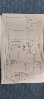
And now for the picture tutorial lol. Ir sensors 1 & 2 there on back straight they connect via that breadboard in the right conner. Powered from the esp32 above just for the 3.3v . the ground comes over to the arduino as well as the signal wires (pin 7 & 8). the breadboard in the lower conner. Yes there is a bit going on there . SD cardreader, a push button and a potentiometer . Their are two different pieces of code that I run . 1 piece opens a file on the SDcard , I you use the pot to bring the car up to speed . it does so via the arduino reads the pot on pin A0 (analog 0) writes it out to pin 9 to the trace on the pwm contronller just before it goes in to the mosfets (2SK3599) pdf attached. after the car is stable and will complete all conners on button press it samples the speed (value between 0-1023 ) converts that to a value to 0-255 writes that to the file . close the file base speed established . load the other code .
read the file convert the value send it to the pwm controller via pin 9 for the base speed . everything is great to this point . the car maintains speed no issue.
I wire in the ir sensors as described above. add the procedure to read the sensors. works fine until you add the car . (stationary running wheels off ground). I think that's it .
Thank again for your help


The pwm controller (input power from wall wart pic at end)


the circuit with just the ir sensors


a timing and scoring with the same sensors . it worked however I was only using the wall wart power supply and standard slot car controller . not currently hooked up

this is my main track . the two light gantry's are for the leds in the track . theirs an arduino under the table that interfaces with the tablet that runs the software for timing and scoring (Race Coordinator).

Yes the initial plan is to have sensors on entry and exit of the corners (at long straights).
1 - if the car is running, wheels raised, the speed is verry erratic, my debug statements in my code show the sensors being triggered.
if the car isn't running and you trigger the sensors by hand the debug statements the system changing the speed properly.
2 - not sure yet if the system responds fast enough yet .
3 - radiated noise is entirely possible. the cars themselves create a lot of noise . early on in the 60's and early 70's they messed with the TV. Some of the manufacture's put capacitors on power rails . now that being said not so much anymore. My tracks and the club tracks I have been to do not have caps on the power rails. could have been the power supply at the time or the TV's got better at filtering it not sure. Now that you mention it when i first got the system up and running just having it run it at a constant speed. it was interfering with the monitor/tv in the background of the pic . I had to move the HDMI cable that comes from the timing and scoring system on the main track.
Currently the power and ground wires on the ir sensors are twisted wires that came from a piece of cat 6 UPT cable. they go over to the breadboard in the corner where i supply power from that esp32 just above, then the signal wires go over to the arduino individually.
On that topic radiated noise , previously i had timing and scoring running on this setup using these ir sensors with no problem. However i wasn't using this Pwm controller just the regular power supply . oh and the timing and scoring is an arduino system . separate of course.
I will re-wire the ir sensors with new wire as you suggested and do some re-routing an see if that helps.
Oh one other thing in my quest to understand what's going on (actually understand what I'm doing) . I stumbled across free courseware from MIT (Power electronics ) the instructor describes my circuit almost exactly right after the introductions . I watched the first 3 lectures yesterday he talked about a bunch of other stuff as well . but i noticed in lecturre 7 he was back to dc to dc converters.
And now for the picture tutorial lol. Ir sensors 1 & 2 there on back straight they connect via that breadboard in the right conner. Powered from the esp32 above just for the 3.3v . the ground comes over to the arduino as well as the signal wires (pin 7 & 8). the breadboard in the lower conner. Yes there is a bit going on there . SD cardreader, a push button and a potentiometer . Their are two different pieces of code that I run . 1 piece opens a file on the SDcard , I you use the pot to bring the car up to speed . it does so via the arduino reads the pot on pin A0 (analog 0) writes it out to pin 9 to the trace on the pwm contronller just before it goes in to the mosfets (2SK3599) pdf attached. after the car is stable and will complete all conners on button press it samples the speed (value between 0-1023 ) converts that to a value to 0-255 writes that to the file . close the file base speed established . load the other code .
read the file convert the value send it to the pwm controller via pin 9 for the base speed . everything is great to this point . the car maintains speed no issue.
I wire in the ir sensors as described above. add the procedure to read the sensors. works fine until you add the car . (stationary running wheels off ground). I think that's it .
Thank again for your help
The pwm controller (input power from wall wart pic at end)
the circuit with just the ir sensors
a timing and scoring with the same sensors . it worked however I was only using the wall wart power supply and standard slot car controller . not currently hooked up
this is my main track . the two light gantry's are for the leds in the track . theirs an arduino under the table that interfaces with the tablet that runs the software for timing and scoring (Race Coordinator).
Attachments
If you load the track with say a light bulb instead of a car, do you have the same issue?
Prove if it's the car or the PWM.
Prove if it's the car or the PWM.
So this pwm converter is not a must . Im not opposed to going a different direction. its just what i had laying around. Not sure how much you know about slot cars . the older controlers were resistive controlers the new ones do pwm (lots of bells an whistles) others with resistor packs with transistors. here's a pic of each

Google suppression.
https://www.slotforum.com/threads/reducing-emi-interference.1493/
Keep on experimenting.
I have lots of 'traditional' Scalextric.
Sadly not used since I moved house over 30 years ago. My loft is too low to be usable and 1:32 takes a lot of space.
Yes, I was aware that hand controller had moved on from a resistance wire.
Thank you very much for taking the time to help me. Sorry to hear you don't have the space any more . Maybe you could get a small HO setup or any chance there's a club in your area ?
Trust me I will keep experimenting! If Carrera can do it so can I . realizing of course they do things completely different.
Thank you again
Trust me I will keep experimenting! If Carrera can do it so can I . realizing of course they do things completely different.
Thank you again