Splitting an output zobel in two, bad idea ?

I'm toying with a compact (60x38mm) layout for a blameless kind of amp, with cfp outputs.

Right now, I've got a zobel network going from the output track to the ground pin of a decoupling cap tied to the negative rail (C5-R7)

I could duplicate the RC network to the other side of the output track, doubling the resistance and halving the capacitance, which would have some advantages in terms of parts (I can use smaller caps to start with). But would that hinder the zobel operation ?

Thanks in advance for any clarification on this. 🙂

Attachments

  • zobel.png
    zobel.png
    99 KB · Views: 237

Crimper recommendation

I have a few projects where I'd rather use crimpers instead of soldering. Any recommendations for a pair of ratcheting crimpers that are under $50? I used a pair of Harbor Freight ones years ago and when everything was lined up perfect they worked well, but I hated the fact that once you hit the first click on ratchet there was no release so you had to waste a connector if misaligned.

Will be using these AMP connectors mainly.

Attachments

  • Screenshot 2021-09-07 at 15-43-41 2-520181-2 TE Connectivity AMP Connectors Connectors, Intercon.png
    Screenshot 2021-09-07 at 15-43-41 2-520181-2 TE Connectivity AMP Connectors Connectors, Intercon.png
    253.2 KB · Views: 208

Audio Research hd220 bias problem (random protection)

Hello to all friends of the forum and well found

sorry my english but i am using google translator from italy

As can be seen from the title I have a problem with this ARC HD220 amplifier, the amplifier sounds good but heats up a lot, and the protection intervenes randomly, sometimes after half an hour sometimes after hours and hours of operation, both at low volumes and also at high volumes, I looked for the services manual to see if there is a bias / offset adjustment but I could not find any documents, opening the amplifier you immediately notice the two power boards L and R (I attach photos) completely separate and well anchored, from what I understand they mount 12 thermo tracks for each side, I do not know this type of Fet / transistor very well so I ask for help from you more experts, I also notice that the pcb lacks the screen printing of the component so I am not even sure if there is a services manual, at the input of the two boards I notice a small trimmer but I'm not sure if it belongs to the bias or not, thanks to all in advance I hope you can give me some good advice

Attachments

  • WhatsApp Image 2021-06-12 at 00.35.41.jpeg
    WhatsApp Image 2021-06-12 at 00.35.41.jpeg
    136.4 KB · Views: 332
  • WhatsApp Image 2021-06-12 at 00.36.00.jpeg
    WhatsApp Image 2021-06-12 at 00.36.00.jpeg
    187 KB · Views: 261
  • WhatsApp Image 2021-06-12 at 00.36.15.jpeg
    WhatsApp Image 2021-06-12 at 00.36.15.jpeg
    123.4 KB · Views: 347
  • WhatsApp Image 2021-06-12 at 00.36.38.jpeg
    WhatsApp Image 2021-06-12 at 00.36.38.jpeg
    264.2 KB · Views: 468
  • WhatsApp Image 2021-06-12 at 00.36.58.jpeg
    WhatsApp Image 2021-06-12 at 00.36.58.jpeg
    207.4 KB · Views: 263
  • WhatsApp Image 2021-06-12 at 00.37.31.jpeg
    WhatsApp Image 2021-06-12 at 00.37.31.jpeg
    127.3 KB · Views: 267

Recommend an add-on manual tonearm cue lift? (Not auto-lifter)

Hey, just wondering if anyone knows of a good manual tonearm cue lift widget you can buy and add to an existing turntable/tonearm? I have a manual turntable with tonearm that has no tonearm cue lift lever of any kind. I'd like to add one.

I found some $65 ones from China on the big auction site, which look pretty decent...
1PC EIZZ 14mm Tonearm Arm Lifter for MICRO 1203 FR64 64S LP Vinyl Turntable DIY | eBay

and Rega makes one for $50, made to add to their turntables.
rega replacement Tonearm Lift/cueing Lever for most rega arms AUTHORIZED-DEALER | eBay

There's a cheaper Chinese one too. Looks like mostly plastic construction...
Tonearm Lifter Safety Raiser For LP Turntable Disc Vinyl Record Player Durable | eBay

Some $130 ones sold by Yamamoto in Japan look very nice, but that seems like a lot of money for this...
Yamamoto sound craft AL-2AL-2 Arm lifter Record Player Accessories 4939325081462 | eBay

The tonearm tube on my setup sits about 3.5cm above the deck while playing a record, so the lifter would have to lift the tube up at least another 5mm to get the needle off the record. If use the Rega one or the EIZZ one, I'll probably need to build a little platform to put it at the correct height. Maybe make a little platform out of a nice piece of dark-stained wood like the Yamamoto one...

Any other ideas for this?
--

others make mod CD-player into stand alone DAC

I read the thread mod Naim CD-player with PMD-200 into stand alone DAC and found it fascinating. I never thought of the idea.
I just signed up and wanted to know have others on this forum done this with other standalone CD players to use their DAC and analog outputs?
Sure there are many low to high cost external DACs available and technology and chips have changes and come far but just this idea was pretty cool.
I would think a 24-bit DAC would still be better than say a old 1990s 16-18-bit DAC...for filters and oversampling, etc.

Bass fix on Chinese Android Auto/Carplay unit

Help with fixing frequency response on Chinese Android Auto/Carplay unit

Hello everyone,

My first time posting here, I wanted to ask for some help with improving the audio output on an Android Auto/Carplay retrofit unit. It is a specific unit made to integrate into the vehicle and so I'd like to use it over a generic solution.

I notice a lack of low end bass output, around 50hz and lower. A frequency sweep shows this as well. I'm examining the PCB to find an OP-AMP with perhaps a resistor/capacitor/inductor on the output stage that is not the ideal value. I found a Class D IC that appears to be the main output to the cars AUX input. Another forum mentioned swapping out a couple of resistors from 1k to 56 ohms and this improved the top end for their particular issue, I was wondering if this could apply to my PCB as well.

The amp on the back of the PCB:

CS3818EO:
https://datasheet.lcsc.com/lcsc/2004300932_SEMICO-CS3818EO_C523711.pdf

Google translate version:
Google Translate

Any guidance or help would be appreciated.

Front of PCB:
front.jpg - Google Drive
Back of PCB:
back.jpg - Google Drive


Thank you,

Cable For Balanced Line Level Signals

Hi,


I have a gig in the open air. The PA is being supplied by a DJ but his mixer is off stage (40ft trailer). Now I need two runs from the main outs of my mixer to the DJ's mixer.


I have shed loads of twin coax, i.e. two shielded cables in the same insulated PVC outer insulator. The two conductors are shielded by braid and the braids are touching along the length o fthe cable. So my query is can I use this balanced via XLRs or would I lose a lot of the interference rejection that you get from a shielded twisted pair audio (mic) cable?

Technics turntable keeps spinning

I have a Technics Quartz turntable that will start spinning the moment it's switched on. It will stop if I keep the start/stop button pressed but the moment I release it, it start spinning again.
For the studio it was used in, it had an external trigger/fader module fitted that I removed but the only mods I found so far was to route orange/yellow cable from the switch through the external PCB and +5V was stolen from Q201.
It gets up to speed very quickly, 33/45 works (needs a bit harder push sometimes), the brake works and pitch control works too.

Attachments

  • skivspelare01.jpg
    skivspelare01.jpg
    313.9 KB · Views: 337

Firstwatt to drive Focal aria 948

So, i've just picked up some focal aria 948 speakers as I got them half price.

But I currently have an aleph j am which I'm told wont drive them very well due to it dipping down to 2.5Ohm impedance between 70-100Hz while being a 8ohm speaker.

I was recommended to build a push pull amp when asking about the aleph j.
To which I was thinking an F4/BA3 and was told that this should be able to handle it.

But i'm just posting to see if anyone things one of the other firstwatt amps like the F5, F6 or M2 would do a better job

Problem with WM8742 at 96khz

Hi all,

I'm using a CS8416 receiver to feed a WM8742 dac, using a coaxial output from an USB sound card everything works ok at 44.1khz and 48khz but if I set the ouptu at 96khz the dac can't decode the stream correctly, there is only noise at the dac output.
The cs8416 seems to work ok even at 96khz (the ouptut signal Bitclock, lrclock and masterclock are ok).
Is there any different setting on wm8742 for >48khz frequencies?
Thanks

Hifonics BXI-1600D second fail (no sound)

Hi!

I have a problem with the amplifier. It broke a second time and the worst part is I don't know why. The amplifier came to me with damaged transistors of the power section (IRF1010N) and the output section (IRF1310N).
When checking the power transistors (IRF1010N), I thought that the control transistors (A1015) were also damaged. I exchanged a total of 28 pieces. 12 (IRF1310N) 12 (IRF1010N) 4 (A1015)

After the whole operation the amplifier sounded and everything was ok. Large electrolytes in the filtering ones look swollen 2200uF 80V and I decided to replace them with all the others.


Unfortunately, I couldn't find the big ones, so I listed all the small ones and that's when it started ... Sorry for the long introduction, but I wanted to describe everything in detail, because it can make a difference. The amplifier stopped playing. The relay is on, the green LED is on, but the output is silent. The TIP41C transistor cannot be touched after about 15 seconds from turning on the power. The tensions on its outputs are: 1 base - 13.4V DC 2 coll - 20.3 V DC 3 emi - 12.8V DC I did some measurements and they are all described and available in the attachments.


After the first repair on the GATE and DRAIN pins of the power section transistors (IRF1010N), I had an even square wave, and now it is not. Gate resistors are ok (47ohm). Voltage on 75V rails on both bridges. The supply voltage is 12.3v and limited to 2A. When TIP41C is removed, the current consumption is 1A, but when it is installed 1.4A.


I don't know why the square wave is so distorted on the IRF1010 and why this TIP14C gets so hot. I bent the output of the emitter, then it heats up slightly, but when all the outputs ... Without mounting the heat sink on it, I would not be able to make measurements with the oscillosc

I read various threads under "hifonics tip41c" but found nothing to help me fix the problem.
I am asking for help, because I have run out of ideas and I don't know what to do. 🙁

Fender London Reverb

I'm re-hab'ing a Fender London Reverb. The schematic states ±18 and ±15 from the low-voltage power supply. I’m measuring around ±15 and ±12, respectively, unloaded. The secondary of the transformer measures about 12-0-12VACrms. (The high-voltage supply is spot on at ±33). I’m wondering if this is normal. I contacted Fender for the service manual, but they demurred. I also searched the web; no joy. If you’ve been inside one of these things, I’d be curious what voltages you found.
Thanks,
George

FS: PF86, 6N3P-EV, 3a5 etc. London, UK

For sale:
- Pair of PF86 unused in original box (I have more) £14.50
- Pair of 6N3P-EV unused in original box (I have more) £5.50
- Pair of 3a5 DHT triodes unused in original box (I have more) £5.50

Reductions for multiple purchases.

Shipping at cost

Attachments

  • IMG_5097.jpg
    IMG_5097.jpg
    242.4 KB · Views: 189
  • IMG_5098.jpg
    IMG_5098.jpg
    325.4 KB · Views: 182
  • IMG_5099.jpg
    IMG_5099.jpg
    271.1 KB · Views: 176
  • IMG_5100.jpg
    IMG_5100.jpg
    409.9 KB · Views: 173
  • IMG_5101.jpg
    IMG_5101.jpg
    156 KB · Views: 174
  • IMG_5102.jpg
    IMG_5102.jpg
    375.4 KB · Views: 66

My 7498 Class D Amp

Hello.
This is my little integrated amplifier that I set up buying parts on Aliexpress.

TDA7498 from the black board.
SMPS 26V 8.5A (221W) power supply for use in industrial equipment.

Digital preamp with 3 line-in and 2 line-out, Bass, Treble and Loudness control and remote control.
Hot glue as a temporary feature to attach the display to the panel until I buy a tool to thread the front panel aluminum.

Speaker output terminal I left RCA until
Purchase the appropriate terminal for the speaker cords.
Hope you like it.

Ps: I bypassed the 2.2ohm resistors.

Ps: I don't know why some photos were inverted.

Attachments

  • 20190913_190300.jpg
    20190913_190300.jpg
    701.9 KB · Views: 511
  • 20190913_190236.jpg
    20190913_190236.jpg
    623.4 KB · Views: 519
  • 20190913_190210.jpg
    20190913_190210.jpg
    649.6 KB · Views: 497
  • 20190913_185632.jpg
    20190913_185632.jpg
    902.2 KB · Views: 507
  • 20190913_185530.jpg
    20190913_185530.jpg
    889.9 KB · Views: 519
  • 20190913_185521.jpg
    20190913_185521.jpg
    754 KB · Views: 200
  • 20190913_185456.jpg
    20190913_185456.jpg
    986.1 KB · Views: 173
  • 20190913_185448.jpg
    20190913_185448.jpg
    855.2 KB · Views: 179
  • 20190913_185426.jpg
    20190913_185426.jpg
    1,016.9 KB · Views: 259
  • 20190913_185439.jpg
    20190913_185439.jpg
    598.8 KB · Views: 259

New pair Laptech HC43 crystal for Well Tempered Master Clock project

Brand new pair of 45M/49M never out of the bag, asking $100.

SC-cut, 3rd O/T
Package: HC43 Cold weld.
Calibration @ LTTP 82.5C: ±3ppm
LTTP:75C to 90C
Load capacitance: 16.5pF
Shunt capacitance C0: 4.0 pF
C1: 0.15fF
Drive level: 100uW

Here are the detail parameters,
XT4338
45.1584M
LTTP 84C
ESR 35ohms
C0 3.4pf
C1 0.4ff
Q 250K

XT4339
49.1520M
LTTP 85C
ESR 36 ohms
C0 3.4pf
C1 0.4FF
Q 230K

Attachments

  • laptech.jpg
    laptech.jpg
    30.4 KB · Views: 179

buzzing

I'm sure this question has been asked a billion times already.

I've got a few of these cheap Chinese amplifiers but this one buzzes especially loudly compared to the others.

Just wondered if anyone could cast an eye over what has been done and comment on possible solutions. It buzzed in two different rooms with different cabling, location and speakers. So pretty sure it's the AMP itself... well if you slot a different amp into the same location the buzzing stops... so 100% related to the design of this particular amplifier.

To be just about bearable in a room the volume knob on the front has to be at about 50%. Any more than that and it sounds like a bee hive.

DSC-0600.jpg


DSC-0601.jpg


DSC-0602.jpg


DSC-0603.jpg

A/C power cleaning

Hello all. I have a buzzing amplifier which has been isolated to an issue with what else is connected alongside. Whilst I recognise different amplifiers have different designs and that some are better and some are worse when it comes to buzzing I'm stuck with this one (I have another two which are ok) and want to make it work rather than rolling back.

The issue is the power coming in is not clean. If you have a PC on the same mains circuit with a typical switching power supply the amplifier will pick this up and create buzzing through the speakers. It's a JLH 1969 variant and supposedly class A so gets hot and runs at full power all the time. So potentially more sensitive than my other amplifiers.

The guy who diagnosed the cause (i.e. if you switch off the PC the buzzing stops) said I should fit something into the line before the power reaches the amp to clean it up. Is anybody else doing this and what have you used?

Dual TDA1541 with LF DEM clock

I have five pcbs (unpopulated) left of the 10 I had made a couple of months ago.
It is designed for use with Ian Canada's I2S to PCM board so one dac receives +/- data for 1 channel, and both receive the same bck and LE.

The left hand dac on the board has a jumper which enables it's mode to be changed from simultaneous to two's complement (I2S) so it can operate alone as a stereo dac. (pin 3 is the data input, pin 4 is not connected)

It would be possible to run them in parallel by reconnecting pin 27 of the right hand dac to +5v.

I am selling them at cost price + shipping for anyone who wants to experiment with single or dual balanced / parallel operation and with EC Designs low frequency dem clocking.

Because the dem frequency is so low, there was no need to use smd components, or mount them as close as possible to the dac (in my opinion).

With pin 16 of both dacs linked and dem clock of around 50Hz, the 1541's have never sounded as good.

There isn't a BOM nor a schematic (straight from brain to layout - hence the missing track!)

Please pm me if interested.

Attachments

  • dbdacphoto.jpg
    dbdacphoto.jpg
    323 KB · Views: 609
  • dbal1541.pdf
    dbal1541.pdf
    177.9 KB · Views: 192

Is a TIP41 a TIP41...need one of a DIY solder kit.

I got a kit similar to this years ago, and it is missing the TIP41. No other details about the part. I see this component listed online, but various versions...not sure if any of them will work, or if I need a specific version of it (the letters following the TIP41). Would appreciate any help you can give!

The kit has a PCB similar to this, but this has different values:

$9.75 - Tesla Coil Kit 15W Soldering Kit - Tinkersphere

This is the diagram for the actual kit I have:
i-s6wfmwj.png


Thanks!

FS: 4 pair Sony 2SK60/2SJ18 VFet

Sony 2SK60 and 2SJ18, 4 pairs available. All HA56 rank.

$120 per pair or $400 for all 4.

Each vfet has been tested at Vds=24V and Id=500ma with Vgs as follows,

2sk60,
1. -10.45V
2. -12.43V
3. -12.55V
4. -13.02V

2sj18,
1. 9.43V
2. 9.43V
3. 9.51V
4. 10.32V

values marked under individual fet too.

Attachments

  • P1030043.JPG
    P1030043.JPG
    301.9 KB · Views: 299
  • P1030044.JPG
    P1030044.JPG
    327.4 KB · Views: 296
  • P1030045.JPG
    P1030045.JPG
    348.3 KB · Views: 301
  • P1030046.JPG
    P1030046.JPG
    274 KB · Views: 295
  • P1030047.JPG
    P1030047.JPG
    331.8 KB · Views: 286
  • P1030048.JPG
    P1030048.JPG
    441.8 KB · Views: 82

AK5394 input circuitry woes ...

Hi all,

I have made an ADC based on the AK5394a which presumably performs very well but behaves oddly when I connect a sine wave generator to the ADC input circuitry.

By "oddly" I mean that the signal displayed by the signal analysis software I use (wave spectra) in no way looks like what it is supposed to look like ... It is becoming quite frustrating so I hope that somebody here may help say what may be causing this phenomenon - I would much appreciate this 😉

I have attached a copy of the schematics involved (pictures 1 and 2). The circuitry is split in two so that one PCB contains the input circuitry and then there is a main PCB which basically contains the ADC (picture 3).

When the input is shorted the ADC output looks like picture 4. Very low noise and basically no issues.

When the input is "open" i.e. nothing is connected to the input it still looks flat, however, at a somewhat higher basic noise level (around - 120 dB). This is to be expected as the 220k input resistor now is not paralleled with the output impedance of a DUT.

... so far so good, no real issues (also keeping in mind that everything is placed out in the open, no shielding at all) ...

All circuitry parts BTW are battery supplied, floating, so that each part has its own battery supply (no ground loops).

However, when I then connect the sine wave generator (Victor's sine wave generator 12 kHz version, - 133 dB THD, 600 ohm output impedance, single-ended output) the ADC output changes completely! This is shown in picture 5.

Basically, it looks nothing like what it is supposed to look like - and decoupling the input with up to 12 nF parallel with the 220k input-to-ground resistor (~280 kHz - 3 dB low pass point when connected to a DUT) does not really change things ...

So I wonder what could be amiss here? As it is I have used the input circuitry PCB (picture 1) in another context (LTC2380-24 ADC) where it performs fine with a distortion level around -120 dB (2H).

If you have some suggestions as to what may be the culprit causing this behavior, I would appreciate your input ...

Cheers & thanks,

Jesper

Attachments

  • input circuitry.pdf
    input circuitry.pdf
    45.5 KB · Views: 207
  • AK5394.pdf
    AK5394.pdf
    133.7 KB · Views: 267
  • input-ADC.jpg
    input-ADC.jpg
    312.9 KB · Views: 308
  • input_shorted.jpg
    input_shorted.jpg
    580.2 KB · Views: 281
  • DUT_connected.jpg
    DUT_connected.jpg
    599.3 KB · Views: 289

No Power Transformer for 150V Ua Driver

I want to have dedicated power supplies for the driver vs. output tubes. The driver tube would have a Ua of 120-150Vdc. Can the mains voltage be used directly, without a power transformer, for the driver tube using the psud schematic below? This is just for the driver tube which requires 120-150Vdc at the plate.

Attachments

  • Screen Shot 2021-09-06 at 7.20.45 PM.png
    Screen Shot 2021-09-06 at 7.20.45 PM.png
    830.2 KB · Views: 167

6L6 used as a.....diode?

I am working on a preamp for a friend and was thinking about this idea:
I have a spare 6.3V winding available on the power transformer.

The main rectification is a bridge.

Can I connect a 6L6 as a diode in series after the main filter cap?
Would the screen be connected to the anode and the grid connected to the cathode?
I have a nice coke bottle 6L6 and it would provide a bit of slow turn on.

Do you see any issues here?
Low current.

Years ago I used triodes as diodes without and issue.

Or would a damper diode be a better choice. Unfortunately I don't have any atm, and want to stick to what I have. I suppose I can use my last 5Y3 for it need be but would rather not (would have to use dropping resistor to bring the heater down to 5VAC)

Live Music Club Sound deadening/treatment

I am working on a project to convert an old dance hall w/balcony into a live music club. The starting sound is super hot/live and my goal is to deaden as much as possible.

The wall height is ~26' from the wood dance floor to ceiling. My vision is to make 4x8 boxes with 1x8x8 pine, with center support, and fill with rockwool. I assume I can double up the 4" rockwool to fill the void). I plan to cover in muslin and hang from ceiling 8" off the wall.

Should I alternate heights to compensate for the taller ceiling? What would be a good square footage of deadening panels that I should start with? Lastly, can I suspend these from ceiling/flat in the center at various areas to reduce reflection from ceiling?

Wall material is brick on 3-sides, and drywall on opposite of stage. It is a rectangular room 40'x100'x26' tall.

Goal to reduce as much reflection as possible (I will work on corner bass traps after testing room).

I suspect I will be coming here with many questions as I learn this process.

Quasi-6th-order series tuned bandpass design

Quasi-6th-order series tuned bandpass design

Hi all, I’m starting to present ?new? type bandpass enclosure - quasi-6th-order (BPQ6) series tuned bandpass. What do you think about?

Generalized design schematic will be:
design-schematic.png

Let`s get started

It is intended to use mainly for fast response (tight bass) along with huge (2.5-3 octaves) flat response – you can get as low as detailed bass (and even infrasound) with it. And this is packed in minimal volume.

BPQ6 can be thought as generic ported (bass reflex) box but with driver(s) inside the port. Similar as quarter wave tubes can be transformed into tapped horn with same action. Also it is special case of series tuned 6-th order bandpass with zero front chamber volume.

Works great as home sub and as a car sub (with EQ-ed for you liking) – thanks to it flat response.

Main idea have next features:

  • Need to get long-stroke driver with moderate or small moving mass for similar class. Driver will face big excursions around system low end tuning freq. Such driver can be tend working bad in ported box at desired low frequencies and peaking after system tuning freq, if you notice it – this driver can pretend to test&play within BPQ6. For example, optimal variant for 10 inch is 400W with Xmax 15mm (one side) for low end tuning @20Hz
  • No massive and high power SPL subs can be applied – very stiff and heavy moving mass, with they you get huge narrow peak at low tuning frequency and silence around it. Also it’s excessive power will not be used at all via bad response and excursion limit
  • BPQ6can be and must be tuned as low as possible while maintain flat response (key to low group delay) – with this “hack” we move bad group delay at tuning frequency deep into low hz zone. For ex. @20Hz we get some hurricane 🙂 and don’t rely delays as important as for ex. @50Hz, because main sound content lies in better hearing sound range after ~30Hz, and lowest end using primarily for it's “effects” or filtered at all
  • Increased efficiency at high end up to second high end tuning frequency (key to “fast bass” and wider response), similar to 6-th order subs, but stronger. Simple ported boxes does not have this effect. Port tapering (horn) can greatly boost this effect. This feature can be used in various ways: supporting driver output at high end if using some heavy driver (you can be sometimes surprised what *this* driver can do, simple ported boxes cannot get this effect)
  • 6-th order series tuned bandpass with front chamber can have similar effect, but front chamber leads to more delay and less cleaner sound and narrower response
  • setting it high and filtering via filter or/and stuffing – you can still get increased response before it but remove unneeded group delays at tuning frequency simply not using it
  • filtering it smart way – via configured filter to make response flat up to that tuning frequency. Use it if you need reach wider response, but with rapid roll-off at end
  • Tuning overall response curve without changing tuning frequencies via driver placement in port, and if driver placed at part side, part can be rotated at 180° and installed in place without remake – I always do tests in either positions to find it best
  • Smaller size for getting same low end response comparing to series tuned 6-th order bandpass, it is special case with zero front chamber volume. BPQ6 is smaller than 6-th order series tuned bandpass for same low end tuning freq. By adding front chamber you lowering high end tuning frequency and smoothing peak at it
  • Easy response recording – place microphone near single port
Design

My driver, for example, far from SQ (maybe 🙂) – it is – Machete M10 D2+2 (Alphard / Deaf bonce brand) – you can find it thiele-small params for reference (params working, no big mistakes, basic of it I test myself and approve).

I have 2 designs for now – Tesseractus and cyclops. All images, hornresp screenshots and real responces see in attachments. Also here 2 txt files - hornresp projects.

Attachments

  • Hornresp_Ek7GE6gNOf.png
    Hornresp_Ek7GE6gNOf.png
    49.5 KB · Views: 382
  • DSC01832.jpg
    DSC01832.jpg
    225.8 KB · Views: 393
  • DSC01864.jpg
    DSC01864.jpg
    131.9 KB · Views: 405
  • Hornresp_gMzFLtSF9O.png
    Hornresp_gMzFLtSF9O.png
    48.6 KB · Views: 432
  • final4-web.jpg
    final4-web.jpg
    132 KB · Views: 433
  • final2.jpg
    final2.jpg
    182 KB · Views: 229
  • tesseractus.txt
    tesseractus.txt
    1,018 bytes · Views: 88
  • cyclops.txt
    cyclops.txt
    1,017 bytes · Views: 76
  • Real-responces.png
    Real-responces.png
    190.3 KB · Views: 232

Crown Power amp directly connected to laptop -not getting enough power

Hi Guys,

I connected Crown XLS2002 directly to Laptop using 3.5jack to 2RCA cable.
I am using this to drive subwoofers.

Input sensitivity is set to .755 in crown amp.
Power output per channel is 650W@4 ohms
The subwoofers are 300W @ 4 ohms

Somehow I feel the amp is not delivering enough power.
Even if I crank full volume, the indicator light is glowing -20 only

I suspect the laptop output signal is not strong enough.
Any solution for this?
Should I use a preamp? If so which preamp?

Any suggestions please ...

Thanks & Regards
Audfrknaveen

Fane 12-250TC - Compact Cabinet

Is anyone using the FANE 12-250TC in less than 80L?

They seem quite good fun/value and Id, initially, like to try them in a compact'ish box: 600x390x260 HxWxD mm.

Speaker Box Lite is telling me 40L will have a QTC of .95 and F3 @70Hz... I assume stuffing and an aperiodic vent will help tame the peaky low end. Looking to crossover to my sub at 120Hz-80Hz so digging any deeper isn’t necessary.


Thanks for any input.

Adam Audio T8V board query

Hi all.,

Adam Audio rates these speakers as 70W bass, 20W treble.

Some internal details here - ADAM T8V - Active Nearfield Monitors - Age of Audio

Looks to me like a 40W stereo burr-brown chip. What I don't understand though is why there's an ADC in there as the speakers don't have digital in.

The Burr Brown can accept I2S. I'm thinking now they are converting the signal to PCM, feeding it into a digital converter to do the low/high roll-off then sending into the amp.

Which begs the question whether these speakers have been made for a digital upgrade. I see a header on the picture. At the moment when I look at my flow I have

SPDIF -> DIR9001 -> PCM1794 -> NE5534 -> XLR -> ADC -> DIG FREQ -> AMP

Seems a natural progression to try and get the DIR9001 signal directly into the DIG FREQ. I'm thinking a SPDIF & DIR9001 in each speaker.

Attachments

  • Ph.-G.-Barbato-Scheda-Madre-Adam-T8V-scaled.jpg
    Ph.-G.-Barbato-Scheda-Madre-Adam-T8V-scaled.jpg
    445.3 KB · Views: 162

Please recommend an enclosure for this 12" FR

I am just getting into speakers DIY, digging through Loudspeaker Design Cookbook currently

However I would like to approach this from the other end as well and get some advice from the experienced crowd

These are specs of 12" speakers I am thinking to start with
What would you recommend to build? This is for my office and probably mono only. Size limitation would be no 1.5m baffles please, otherwise open to ideas

Fs 38Hz
Re 6R4
Qts 0.42
Qes 0.46
Qms 4.29
Vas 179l
Mms 43g
Cms 0.41mm/N
Xmax 4.5mm

Thanks

Hashimoto PT ratings

I don't understand the DC rating for some of the Hashimoto power transformers for full-wave center tapped rectification.

PT-150 for example, is rated at "280V-250V-220V-0-220V-250V-280V: 0.16A AC (220mA DC with Full Wave Rectifier)"
For FWCT, shouldn't the DC rating be derated 1-1.2X from the AC rating?

Another example, the PT-300B, which is specified for bridge rectifier, seems closer to my expectation as DC is derated by about 1.6.: "20V-0-280V-310V-350V: 0.53A (330mA DC with Bridge Rectifier)"

New Crossovers with Hz/db switches & DIY speakers

Hi I just received these crossovers today I realize it's not ideal for my set up but until I get some different ones I'm wondering what these switches are for there are switches for each for the following as in pics.

0Hz-30Hz for bass
0Hz-30Hz for mid
and a
0db to 3db for treble

The mid to treble crossover frequency on this crossover is at 3500 KHz but after much searching and emails I have been not been able to determine the bass to mid crossover point on this crossover. I think it's around 2500 KHz would anyone happen to know for sure?
TimScreenshot_2021-07-06-19-46-28-075.jpeg

IMG_20210715_114234_885.jpg

IMG_20210715_114304_165.jpg

Maximizing Subwoofer system "throw" - Excursion vs cone area.

Guys, I thought I was sure about this, but no longer so, and I REALLY need to know for sure:

This isn’t a question of sealed vs ported vs TH vs FH.
And this DEFINITELY is not a questionn about SPL. - I have found countless threads about that.

For this thread, I’m concerned only with LF “throw." My definition being: The ability for a sub system to maintain as even an SPL level as possible over distance. For this discussion, let's say from around 10 feet to 100 feet. (I do small gigs.) I have always been of the opinion that total cone / port / horn mouth area is what matters. (More speakers at lower volume each.) Other people seem to think that cone excursion & total dispersion are all that matters. Or maybe it’s displacement, but it's the same result in that case: Less speakers with more power to them / more excursion.

(Again, this is not a discussion of ported vs horn loaded, etc.)

Here’s the simple setup / question: (I know this is fairly obvious, but I want to be sure we are discussing exactly the same thing.)
——————————————————————————————

Take three of any subwoofer you like, and set them up with a pair of decent tops. Tops that should carry well over the same 10 - 100 feet test range. For this test, put the tops right next to each other, and not too high.

Run your amp into sub “A” by itself, and get its output balanced with the tops.
Also test with a meter.
Now listen at 100 feet and note how much apparent loss there is.
Also test with a meter.

Now repeat this test, except with both sub B and sub C running, (No sub A) but with the subs amp turned down, so the tops are still balanced.
Also test with a meter. At ten feet, I would assume the subs’ spl level will be very close to the first test.

OK, so at 100’, is there any difference in balance / in subwoofer spl?
Based on my own (limited) experience, and just using my ears, there will be. Test #2 will give noticeably more LF at distance.
- But some pretty intelligent guys disagree with this, so it’s driving me nuts. Especially since this is driving the design theory behind my new subs system build.

What say you? And why?


My theory, assuming that my ears are not fooling me, or that it has something to do with small room nodes and compression, is thus:
If you can excite more air molecules at the source (the subwoofer) but use less energy per molecule, then the less loss there will be as the waves travel through the air.
That just makes sense.

The guys that disagree say that more cone excursion creates just as much dispersion, thus just as many air molecules moving.

My counter to THAT is, even if it’s true (I don’t know) there is more energu behind those molecules, thus higher resistance through the air, yada yada yada….

Am I wrong?

I’m planning on building four smallish subs, and running them at “medium” power, instead of two equal subs pushed really hard. This gives the advantage of using lower-powered and hence more sensitive drivers. This also may have a small advantage is sound quality, due to less excursion. - But that doesn’t matter for this discussion. I just want opinions on the issue of “throw.”

thx.

Converting active subs to passive query

All the cheap amplifiers in my H/T speakers are on the way out, several have died already and these cheap amps seem to not worth repairing even if the faults are minor.
I'm considering biting the bullet and converting them all from ported active to simple sealed passive.
I have no data for the drivers and still no test gear apart from the multimetre but the 12" are reasonably sized magnets with about 8mm of travel P2P and the tens are a very common generic with bigger magnets and lots of travel
Pix later.
Had these for a dozen years or more so I've got my monies worth from them but I see no need to trash if I can make them work passive.
Any tips; hints; pitfalls; advice for me before I start?
It will mean I have a dozen small toroid transformers [ maybe 150- 200VA] and associated heat sinks here that may have some small value

Crossover accessories terminology help please

Hi guys,
I need help with choice or terminology of speaker crossover parts.
I have all the drivers, capacitors, coils and resistors.
The crossover will be quite complex so I want to figure out layering and connections between the components. It will by trial and error, thus I want to avoid much soldering at first stage.
Can not find anything useful on internet as I am not using proper terms.
I want to connect wires to wires - multiple or single “input” wires to one or more “output” wires.
Initially I had an idea of grouping of cheap russian PETP capacitors (I bought already) instead of using single high value (15,33,56,220 and 600uF) expensive PE caps.
At the end, I also bough those higher value caps in form of bipolar caps, so that will be first step, and maybe sufficient.
There should be some kind of buses/ rails available to connect more caps/ components into one output..
Thank you for the suggestions.

Slots and Dados vs just glue?

As part of a woodworking forum I asked an opinion of what a slot/dado would do to help a cabinet vs just glue. Of thos who replied, a glued joint is as strong or stronger than MDF itself. The tritrix has slots cut appx 1/4" into the sides for the TL divider to fit into. The corner waveguides do as well. So My question is of how important is this joint if the divider is well glued and clamped just to the surface. Also, the slot/dado does not run the full length of the TL. Both ends have appx 4 to 5 inches that come up out of the slot/dado and glue to the surface.

The search feature here turns up threads with hundreds of pages and no way that I know of to find the exact info so I am asking this in here as well.
.
.

Attachments

  • cab3.jpg
    cab3.jpg
    98.2 KB · Views: 267

Help recommending a preamp that is 5.1 but has 2.1 or extended stereo functionality

Hi!

I'm a complete beginner in the topic, I have a cheap 5.1 system with a broken amp (and it was equipped with a rather overly complicated preamp), and I thought I'd give a try to replacing the boards and give some update to the system, since I like the speakers.

My main concern on the preamp is that it should have a 2.1 functionality (where the sub plays the bass frequencies in mono) or an "extended stereo" functionality, by which I mean that left front & left surround play left, right front & right surround play right, sub plays low frequencies mono, center is either mono or silent. This would be a dream, but I'm completely fine with a 2.1 mode.

I've found some cheap Chinese boards (AIYIMA NE5532, AIYIMA NE5532 5.1 Tone Preamplifier Board HIFI 5.1 Preamp Volume Tone EQ Control Board DIY for 5.1 Amplifiers|Amplifier| - AliExpress) that look good, they have 5.1 and 2.0 inputs, but I don't know how do they behave with the 2.0 input. Can somebody that knows this kind of preamp tell me what happens if I connect a 2.0 input to the aux-l and aux-r? I see no switch to switch between the inputs, and my concern is whether this input would only be played in the stereo speakers, or the bass would go to the sub?

I also have a transformer leftover from the original amp, which has dual 11V, dual 12V, and normal 10V ac outputs. I've measured the 11V to be 12V+, is that enough for this preamp?

In case you know a preamp that meets my expectation and is in the price range, please also share.
Thank you!

Free Large Toroidal Transformer 140 vac +50+40

Free transformer for anyone who wants to pay the shipping. It is big! I bought it to possibly repair a Hafler power amp but ended up not needing it. It was supposedly out of a big Arcam power amp. It looks to have 140,50vct plus a seperate 40vct. I don’t know the current ratings.

Shipping is $22.00 in flat rate box US only.

Attachments

  • BA7FB2ED-2F93-4E7D-9BD9-750B04E28F2E.jpg
    BA7FB2ED-2F93-4E7D-9BD9-750B04E28F2E.jpg
    790.7 KB · Views: 180
  • 5E9AA44B-1395-4F28-BF0D-0C5F79E294D4.jpg
    5E9AA44B-1395-4F28-BF0D-0C5F79E294D4.jpg
    806.9 KB · Views: 166

The Advantages of Floor Coupled Up-Firing Speakers

:cop: Note: Thread title changed.

Reading what many people in audio wrote on the subject of loudspeaker design (Carlsson, Beveridge, Moulton and Linkwitz were my main inspirations) I came to the conclusion that the real issue is that loudspeakers and room form one system.

Recently I had an impression that this I also a view of gedlee (Dr Earl Geddes) when he wrote that the most important parts of his book are those concerning waveguides and room acoustics ("Don't read the stuff on non-linearity, but fully grasp the chapter on waveguides. Thats what I would say today.That and room acoustic")

Later I came to believe that what Dr Geddes writes on the topic of room reflections is in the end of the day the same thing that Carlsson, Beveridge or Moulton and also Linkwitz have written on the subject. And that in their designs they wanted to achieve the same end - to eliminate the detrimental effect of room reflections.
And yet their designs are so much different!
Apparently there are many ways to achieve the same. Linkwitz’s experience with subjective evaluation of his own an yet very different dipole and omni designs confirmed this for me.

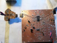
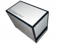
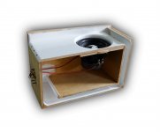
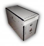
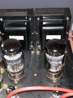
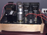
I have very unusual loudspeakers which I have built some time ago with those room-speaker interface things in mind. These are very short omnidirectional loudspeakers. They are just 20 cm high and have 8 inches wide range driver on top and firing upwards.
The loudspeakers are to work on the floor – the driver is only 20 cm above the floor – and against the wall.

In this positioning they happen to be quite similar to the late Stig Carlsson designs (carlssonplanet.com, but the Carlssons are two-way and much more complicated because of that) but were not inspired by them.
I didn’t know the Carlssons when I was building these and my first and main aim was to eliminate the detrimental effect of early floor and ceiling reflections without resorting to unavailable true linesource (like Beveridge)
The second aim was to build loudspeaker least visually obtrusive, loudspeaker that would be practically invisible in the listening room (which in may case at the time was also a living room). Perhaps it was even equally important goal.

But frankly speaking I wasn’t thinking a lot and I think now that I really didn’t know what I was doing 😉 and still I don’t – I have no technical background – and it was and it is all mostly intuitive. 🙂

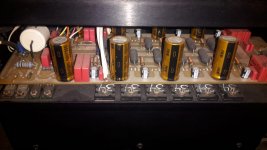
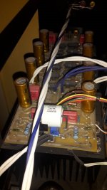
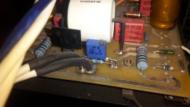
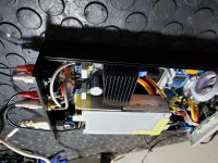
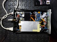
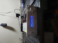
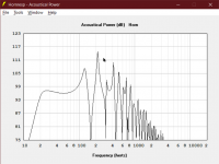
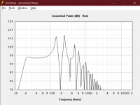
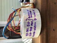
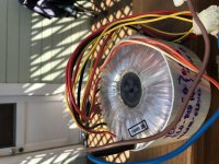
But the outcome appeared to be quite satisfying. This is still work in progress. Achilles heel of the loudspeakers are 8 inches Fostex wide range drivers which have major resonant problems in the break-up area. Out of the box they were literally howling at me. After some driver-mutilating (i.e. tweaking) I can say that these problems are only partially solved for the time being and I am looking for a different driver

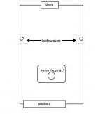
Soon I will have a new listening room that is 350 cm wide and 550 cm long. Not too big and not the best proportions but I can arrange it specifically for audio purposes.
I am considering positioning the speakers against the opposite longer walls (scheme attached). Stereo basis would be 330 cm. The listener is to be located 200 cm from stereo basis, 250 cm from both speakers

All this with the questions of minimizing early reflections in mind and particularly with what Dr. Geddes has written on this forum.

A big thanks goes to Dr Geddes! 🙂

To my not very big surprise the resulting set up happens to be very much like Beveridge positioning of his line source electrostatics.

The positioning would give very early reflections (VER) <1 ms from adjacent wall. I hope that they would not be strong enough to become audible problem because the Fostex is quite beaming (I don’t know for sure but 8-inchers are typically 7-8 dB down at 1 kHz at 75-90 degrees and 12-15 dB down at 2 kHz). I am also considering using small Carlsson style absorbers effective for midrange and high frequencies as an option.
Apart from those very early (and hopefully low in level) VER I expect that:
- significant reflections off the adjacent wall would not reach the listener
- floor reflection would not reach the listener
- first reflections off the front wall and off the back wall would reach the listener 9.3 ms after the first wavefront
- first reflections off opposite walls would reach the listener 8.3 ms after the first wavefront
- first reflections off the ceiling would reach the listener 8.8 ms after the first wavefront (ear at height of 90 cm, ceiling at height of 300 cm)
It seems that apart from those earliest reflections <1 ms all other reflections are delayed more than 8 ms and caught by proximity (Hass) effect.
And all this in a relatively small listening room. The bigger the better.
Also I am considering using some wide band absorbers to reduce the reverb after first 50 ms as Moulton recommends.

What do You think? Any suggestions? Ideas? Your own unusual setups?

best,
graaf

Attachments

  • room.jpg
    room.jpg
    10.3 KB · Views: 13,929

Genelec 4020B input connector? (Green strip type)

Does anyone know the Mouser/Digikey part for connecting the signal inputs to a Genelec 4020B? Image below.

Its one of those green strip euro types, 5 contacts.

There are so many variations it boggles the mind, figured someone out there would know.

Image (found online) attached, looks just like this.

Attachments

  • genelec 4020B No. 1.JPG
    genelec 4020B No. 1.JPG
    66.7 KB · Views: 120

FS: Ian Canada digital gear - LifePO4, FiFoPi Q3. Plus Pi2AES

Hi all, have some things to sell. If it's allowed, I'd prefer an email to trvtec@gmail.com over a PM just because I haven't been frequenting the forum recently but either way should be ok if PM is better for you.

I have the following for sale:

Ian Canada LifePO4 Mk III
An externally hosted image should be here but it was not working when we last tested it.

Includes a Dell 300W power supply for charging, as well as 10 26650 batteries. Not willing to piecemeal this. $275 plus shipping to the US.

Pi2AES
An externally hosted image should be here but it was not working when we last tested it.


An externally hosted image should be here but it was not working when we last tested it.

- early revision of this streamer. Does not come with any extras, no power supply. Requires 12-19V, can power a Pi3 or Pi4 with one PSU. $100 shipped, US only.


Ian Canada "Digital to digital converter" with USB in, i2S out. Rates up to PCM384 (8x) and DSD256 are supported. AccuSilicon clocks are included, as are the standard Ian Canada oscillators. Will not seperate. HDMIPi is modified per Ian Canada instructions. Requires power supplies in accordance with Ian Canada documentation.
Includes:
Amanero Combo384 USB receiver
FIFOPi Q3 reclocker with AccuSilicon 90/98 oscillators
HDMIPi mk1 modified
$275 shipped for everything, US only. This is a little hard to get pictures of without taking it all apart (which I'd rather not do). If more pics are needed, I can try to get better ones.
eVpe5Y6h.png


All Ian Canada and AccuSilicon items were purchased this year from audiophonics.fr. Pi2AES is currently backordered, but I bought it new from Pi2Designs a couple of years ago.

My email is trvtec@gmail.com. Paypal only please. Prices include fees.


EDIT 9/8/2021 - All items have been sold. Thank you!

Nakamichi AV-10 - No/Limited Volume

Morning Folks...

I already searched for this and its kind of rookie question given the expertise Im reading on the site.

My Nak AV-10 is producing a whisper of a volume from one channel and none from the second. I havent plugged it in in 5 years but I recall both channels were doing the same thing.

I think the power transitors are shot or certainly the final drive section is in need of help. Its just a surround sound system and something I use at low-moderate volume with guests.

Is it worthwhile to fix it?

Anybody know what transistors I need to replace or should I just replace all of them?

Any suggestions on where to get parts or a kit?

(I have no problem upgrading components)

Thanks
Soldering iron is ready to go!

Buzz or Noise in Distribution Amp Output

I have a multi-zone audio distribution system. Each output is 25w/ch and can support 8 or 4 ohm loads. In some rooms, I hear a hum or buzz when the system is off. In some cases, briefly turning the zone on will alleviate the matter temporarily. Doing so often results in a small audible "pop" as if it were relieving pressure at the output. In some areas, this action does not change anything.

I do not have info on the type of amp used. Sources and amps are all on the same power circuit. In my mind, this eliminates a ground loop scenario and points to a cheap noisy amp.

At present, every zone is an 8ohm stereo pair.

Is there something that can be done to bleed off this noise at the amp? Possibly a small resistor across the speaker outputs? Any suggestions?

How do you amplify a speaker level signal?

No hifi, but still 2 channel.... I am looking for a relatively inexpensive solution to a quirky problem. We replaced our security system and failed to consider how the audio events would work through our automation system. We have touch panels at each door and a wired balanced stereo audio feed goes to the touch panel and you hear the audio when you open an armed door or arm the system.

The new panel (Elk M1 Gold) panel has an unbalanced mono output for siren, and a unbalanced mono output for voice feedback. The prior system combined these two signals into an unbalanced mono out and life was great. I jumped the negative and the ground on both channels (if that is relevant).

ISSUE: Audio from the siren feed (the countdown beeps) is almost inaudible. The voice feedback (system is armed) is overdriven.

QUESTION: Assuming this is an amplified signal, is there an inexpensive way to amplify the siren feed? The security panel offers a variable audio level for voice, but siren level seems to be fixed.

Added data point... there is a simple speaker that came with the new panel and when connected to either siren or voice, things sound fine, but the panel is too far away from any of the doors to be useful from that location.

Any suggestions?

FS: Single Ended Output Transformer 5k/25watt

For Sale is a pair of 25 Watt Single Ended Output Transformer made by Heyboer.
Specs : 5k primary 25 watt, 40%UL with multiple secondary taps 4,8,16,32, 300ohm. This are used and in great condition. This are similar to edcor CXSE 25 watt in specs. Pics are from When they were used in a SE kt88 in UL. This is a very good sounding opt.

Asking $150.00 from 60060. Pls mail me at ivardlr@gmail.com

Thanks

Attachments

  • 56965300-F32B-4563-B9BF-C14D5978AE55.jpg
    56965300-F32B-4563-B9BF-C14D5978AE55.jpg
    546.7 KB · Views: 302
  • B60629AE-5D49-43AD-A8AC-3B9DCD4C9DDE.jpg
    B60629AE-5D49-43AD-A8AC-3B9DCD4C9DDE.jpg
    779.3 KB · Views: 301

First tube amp build - not going too well..

Hi everyone,

i finished my first tube amp yesterday and went to turn it on today but it does stuff it's not supposed to.

The Amp uses 6n1p's driving EL34's connected in Triode mode, i got the schematic from a friend who has experience with tubes and built multiple amplifiers already so i trusted him on that..:

QcrclQH.png


The speaker connected to the left channel emits a continuous popping sound and when applying an input signal it comes out as extremely distorted.
The right channel has another issue, it's quiet at first but then starts emitting a distorted sounding hum that gets louder as the tubes warm up to the point where i have to turn the amp off to not damage my speakers.

I swapped out the tubes but the issues persist so i don't think they're faulty.
I also double checked every connection and wire and could not find any issue.
Here's an image of the guts, i know it's far from perfect:

eMSuJz4.jpg


So yea, if anyone has an idea about what could be wrong please tell. Maybe it's even the schematic itself that can't work that way? He told me he based it on an existing design and modified it..

Thanks in advance!

Logarithmic power VU meter

To indicate the power level, I came up with a small driver for the VU meter


Log-amp-for-SO-53.jpg


The amplifier is a chip for hearing aids. The logarithm occurs on the nonlinear characteristic of the diode chain. At the output, a forcing chain is added, which allows the arrow to move quickly forward and slowly roll back.

Gain characteristic:

Log-amp-characteristic.jpg


General view of the structure with the SO-53 VU meter

SO53-log-top.jpg


SO53-log-botton.jpg


There is one drawback, at elevated temperatures, the driver lies, so this driver is of little use in "hot amplifiers" without its own cooling.

A highly detailed, analytical amplifier for the Beyerdynamic T1?

Good day everyone 🙂,

I'm looking for a DIY solide state amp for my Beyerdynaic T1 that has a high resolution and plays extremely clear, detailed and analytical, preferably together with a holographic presentation - (almost) exactly the opposite of my current amplifier for the T1, a slightly modified Darkvoice 336e, which has its own charm with its warm, nicely colored sound (and a nice holographic presentation), but sometimes I would like to experience the other sound of the T1, depending on my mood.

Do any of you have a recommendation or two that I might enjoy?

Greetings
Mike

Baffle step compensation circuit for bookshelf speaker

Hi Guys, I am building my first bookshelf speaker ever.

To keep my first build as simple as possible, I decided to reuse the enclosure from my old Wharfedale Valdus 200 s(12 Litres) and bought Alpair 10p fullrange drivers that should fit nicely, but by the spec they require a bit more enclosure volume for good bass extension.

I can sacrifice sensitivity so is baffle step compensation circuit a way to go to boost the bass?

I already built the bass reflex prototype, but have to tweak the bass (+8db) via amplifier tone controls to get the bass a like. I would like to het the same result without using tone controls.

I am wondering whether baffle step compensation loss circuit starting at let’s say 100 hz is a way to go.

Many thanks for any hint,
Pavel

Fender super reverb 1979 strange sound

Hello to the forum .. 3 weeks ago a friend of mine brought his amp for repair because it did not work (the amp is a fender super reverb 1979 diode rectifier). when I opened it it made a buzz and the guitar signal could not be heard…. finally 2 tubes 12ax7 had burned and the 1 6L6… also had the hum balance pot damaged and I replaced it .. the 2 12ax7 were replaced and I also changed the 2 6L6 I just could not find jj matched and I got 2 unmatched tung sol… the amp just worked made a buzz .. which buzz I turned off by adjusting the output maching tubes pot, as exactly FENDER mentions in the manual .. the amp was playing perfectly! .. yesterday my friend notifies me and tells me that he started making this buzz again .the amp plays normally, it just makes this buzz .. I told it to adjust the output maching tubes from behind and it will decrease… it did not disappear, it just decreased .. what is wrong? was it the fault of the 2 6L6 that are not mached? Is the main transformer power to blame because it has it at 220v? I say this because the transformer also has a 240v option. and from what I measured the current here in Greece it is 230v…. what could be the problem?

thanks
F65AC630-FCD5-4077-A4D7-F2B8B8048406.jpegFF886052-2290-4144-B2B0-AEF487E494B8.jpeg46FD52E3-FE81-4EE1-8A5C-603226175464.jpeg

Soldano hot mod

Hello guys … today I saw something very interesting .. there is a patent of SOLDANO for the amps jcm800 and jmp and it is called hot mod. is an adapter that accepts a tube EC10 (6K11) and greatly increases the gain on the amplifier .. put it in place of v2 and ready .. out of curiosity I searched for this patent and found only one schematic .. just looking at it I think it is wrong or am I wrong… in schematic pin 7 (the second grid of v2) has no contact anywhere .. is there a case for the signal to pass elsewhere ??AC1F77C1-F0C3-46E8-8C0A-BA3053A41DE2.jpeg

6F8D4CA6-1A92-49C9-A7E1-78154A33B0F8.jpeg

50CD41ED-1A7F-45D3-8FC7-7E8F04B1FA6C.jpeg

XO slope and why you need DSP

So I was reading about a bleeding-edge Manger speaker where they favour 96dB/8ave slopes. So I thought I'd see if my tweeters should come in at L-R48 instead of L-R24 (only tweeter moved), at 3kHz?

With a DSP, takes about 20 seconds to switch from one slope to the other. Or to change the XO frequency a bit. Or to..... And it takes just 3 seconds to replace the old setting memory with the new settings (Behringer DCX2496).

Attached are L and R systems with the flatter curve in each being the .... you can guess for yourself (or read the labels). Distortion a bit lower with 48 but impulse - at least in first milli-second something of a toss-up.

I just can't understand how a DIY person can be without DSP, even if just for setting up their HiFi.

B.

Attachments

  • Left XO slope.jpg
    Left XO slope.jpg
    92.2 KB · Views: 679
  • R XO slope.jpg
    R XO slope.jpg
    92.4 KB · Views: 683

NE5534, Vcc > +/-10v pointless for 9v balanced output?

Hopefully the title says it all. In the BurrBrown (Ti) document attached the NE5534's are provided with 15v. Another design I've seen uses 12v, while the peak output for balanced is 9v.

The NE5534 isn't rail to rail and requires 1v headroom as a minimum. Therefore, in this application is there any point in going above 10v? As I see it it'll just waste the excess as heat in the op-amp.

Attachments

Projects by fanatics, for fanatics
Get answers and advice for everyone wanting to learn the art of audio.
Join the Community
507,637
Members
7,881,827
Messages

Filter

Forum Statistics

Threads
405,933
Messages
7,881,827
Members
507,637
Latest member
noname203