Details from ML-1...

Hi there!

Just accidentally found a picture of a Mark Levinson ML-1, and admired it for the overall clarity inside and out. (especially noteworthy the labeling on the top-cover!)

But I'd like to ask about two other things:

- The balance-controls are two separate attenuators, going from off, -4dB to +5dB, with a funny looking PCB behind it. It looks like a quite simple shunt-attenuator or something similar, but... is this (attenuator-board) known ?

- On some resistors, ferrite-beads are around their legs. Is that a useful detail, or just another extravaganza?

Attachments

  • ML-1-topcover.jpeg
    ML-1-topcover.jpeg
    108.7 KB · Views: 86
  • ML-1.jpeg
    ML-1.jpeg
    269.4 KB · Views: 83
  • Bildschirmfoto 2021-09-22 um 14.08.41.png
    Bildschirmfoto 2021-09-22 um 14.08.41.png
    25.9 KB · Views: 81

Mastering Labs crossover question

Question regarding the 16 ohm, 1500 HZ, Mastering Labs crossover for Altec 604E:

I just purchased a pair of these which apparently were originally used in the "Super Red" version of the "Big Red" monitor. Why do I think this? In addition to the 4 connections required for hookup to the 604E driver, it has another pair of connectors. My guess is that these extra two connectors wre for the supplementary 15" woofer in the bottom of the "Super Red" cabinet however they don't connect into the crossover circuitry at the same locations as the primary woofer connector leading to the 604 driver's LF section. Perhaps the two EQ adjusting controls do not affect the lower woofer.

I have one unit installed and I'm listening to it now. The extra connections are unterminated - simply unconnected and separated from each other. The speaker sounds fine to me.

My question is: Is it electrically safe to simply ignore this extra connection and not connect it? Or, should a resistor be connected across the connectors to simulate a speaker load?

Thanks in advance for any answers or advice!

Best to all you Altec enthusiasts out there!

Fred

Schematic question

Hi,

I would like to know what is the purpose of these diodes (CR7/CR8 and CR9/CR10) connected this way in the attached schematic.

Attached here are: full schematic of the SUMO Andromeda2 amplifier (PDF file) and a screen capture (PNG file) where diodes (CR7/CR8 and CR9/CR10) are boxed in red for easy location on the schematic.

I am restoring an old Musical Fidelity A1 amplifier and found the same diodes configuration than on the Sumo. I replaced the diodes by a wire and found no changes in the amp behavior.

Any info would be highly appreciated,

Vince

Attachments

Tube/Hybrid amp suggestion

Hi all,


I recently decided that i want to build my very own first amp 🙂

Now choice is coming down to following designs..


1. Tube preAmp + Tube powerAmp in SE config
2. Tube preAmp + LM3886 powerAmp


I have finished my speakers, you can check details in pictures.


Currently its connected to 3.6w 6p6s SE tube amp, and it sounds great, but i would like something with little bit more power. My goal is around 20-30w per channel.


Any recommendations and/or schematics ?


*NOTE*
Im a total noob when it comes to this, i have some very basic knowledge and soldering ability, so i apologize in advance for stupid questions.

Attachments

  • freqResp.JPG
    freqResp.JPG
    54.3 KB · Views: 476
  • phaseImpedance.JPG
    phaseImpedance.JPG
    61 KB · Views: 473
  • WhatsApp Image 2021-09-09 at 9.59.26 PM.jpeg
    WhatsApp Image 2021-09-09 at 9.59.26 PM.jpeg
    244.3 KB · Views: 476

Help With Klipsch KA-1000 blown amp

Hi. I have a Klipsch KA-1000-THX amp that drives two KW120-THX subs. Last summer, I noted that the amp was not powered up. After opening it up, there was a blown capacitor on the power board with some charring on the under surface of the board damaging the board and some surface components. I had my bro, who is a computer guy take the board to an IT tech that repairs computer motherboards that offered to do a repair for me. She started to clean up the board and wanted to repair it, but she cannot find a schematic for the unit. I contacted Klipsch, who said that the unit is discontinued, and they do not do repairs any longer. They suggested checking with another company, which told me the same thing. I asked Klipsch if they had published the schematic for the unit, and if it were available for D/L or purchase, and they said it was not available. After an exhaustive search online, I was unable to find the schematic. I went to eBay and found a non-working unit being sold for parts, and I picked it up, thinking it might have a good power board or have a problem elsewhere in the unit. Unfortunately, it had the exact same problem and damaged parts, and it appeared that someone had already done a repair on this second unit. At this point, I am hoping someone on this forum may have access to the schematic, so I can get the unit repaired. I would also entertain the idea of getting a replacement board, if one is available. There are a couple "new" units available on eBay, but I am not sure if I want to put any more $$ into something that is so tough to get repaired. Any help would be much appreciated! Thanks!

docjj1
Williamsville, NY

Attachments

  • IMG_2607.jpg
    IMG_2607.jpg
    514.4 KB · Views: 439
  • IMG_2605.jpg
    IMG_2605.jpg
    617.9 KB · Views: 416
  • IMG_2606.jpg
    IMG_2606.jpg
    626.9 KB · Views: 431

Novacore planar tweeters

Hey guys,

Wondering if anyone here has experience with Novacore brand tweeters, they seem to be "replicating" GRS/ BG planars.

Was searching for some BG Neo8's or similar for a line array and came across these Novacore High power aluminum Planar transducer Amt Ribbon tweeter for DIY monitor HiFi audio home theater 6Ohm AMT 920 NEO 8|set design software free|set therapytweeter box - AliExpress

Looking at the response graphs (only) they look fairly comparable to the BG neo 8's https://www.parts-express.com/pedocs/specs/264-713-bohlender-graebener-neo8-pdr-specifications-44311.pdf

I am tempted to buy a few samples but just curious if anyone has seen or used their products before? Searched for Novacore on the forums but found nothing.


Thanks guys.

PSU final implementation questions

I hope this will be my last post about power supplies before I start spending money...

1. Is there a clear benefit to building my own diode bridges? It seems like a toss-up for most people.

2. What does the value of the PI resistors affect, and what would determine if I should use the Optional PI resistors?

3. I assume I should error towards a higher value bleeder resister?

4. I'm planning on building a single power supply for my BA-3 build. Any reason that's a terrible idea?

15 inch rear loaded horn

Hi everyone,

I'm planning to make a rear loaded horn with my 15 inch Monacor SP-38/300NEO speakers. However I have some concern by the design, since I yet haven't encountered a horn this big anywhere on the internet (without having an infeasible design). And also since this is my first horn, I have some further questions:

Is it possible to make a efficient horn out of a 15 inch speaker?

Since i can't find any design plans, is it possible to scale up an existing horn enclosure? i.e. this fostex plan (by a scale factor of approx. 2): http://www.fostexinternational.com/docs/speaker_components/pdf/recom_enclose/206e_enclrev.pdf

I can imagine the speaker is producing a lot of pressure within the enclosure. Should I be worried about the well being of the speaker cone or the pressure chamber?

If any of you can recommend an alternative speaker plan, please be kind to send it my way.

Thanks in advance to all of you!

Subwoofers hiding in furniture

I made this subwoofer for my brother in law for his vacation condo. He wanted something with moderate performance, low frequency reach but not loud enough to bother the neighbors if a renter cranks it way up. But most importantly he didn't want a subwoofer box visible. So I went up and measured the height and style of the end tables in the room and then made a new end table with a subwoofer inside.

Here's the posting I made at Parts express since I don't have a good image hosting site set up for here:
End Table Subwoofer | Parts Express Project Gallery

I learned something along the way that might be really useful for you guys. Furniture is huge. This box only required about 1 cubic foot and I had a hard time making a useful end table small enough without building a box within a box. The point being, if you wanted to build a big 2-4 cubic foot enclosure for some monster sub this might be a great way to hide it in plain sight in your listening room even if it's only a "just for looks" piece of furniture.

Silk substitute for a JBL 052Ti

I have a pair of JBL 4412A's for my office speakers which I like. I had an Adcom GFA-555, then a pair of GFA-565's. I have been wanting to try Bryston so when a 4B came along I got it. The mids are pretty good as is the bass. The high freqs were harsh. I mean harsh.

I talked with a few people. The consensus was that the high freqs of the 4B are too bright and combined with the Titanium tweeters it was not going to work.

Supposedly the 4B ST is a significant improvement and an SST even more so. Last week I saw an SST for a reasonable price and bought it.

It is much more refined than the 4B. The mids are quieter and more detailed. The bass is clean, tight, and decisive. The highs, while certainly not shy are much more in line with the lower freqs.

It is still brighter then I would like. People familiar with Brystons think they don't pair well with titanium tweeters. I would like to try some silk tweeters.

I am looking for recommendations. If I find a replacement I like the 052Ti's are obsolete so I would have no problem selling them, plus I have some spares I could sell as well. That gives me $3 - 400 to work with for silk tweeters.

Here are the specs for the JBL 052Ti's;

HIGH FREQUENCY DOME RADIATOR:
Nominal Diameter: 25 mm (I in)
Voice Coil: 25 mm (1 in) diameter copper
Magnetic Assembly Weight: 0.91 kg (2 lb)
Flux Density: I.5 tesla (I 5,000 gauss)
Sensitivity? 92 dB SPL. (2.83 V) at I m (3.3 ft)

The flange measures 5" across.

Thanks!

Help choosing loudspeakers for 2000 Square feet hall

I am planning to buy 12" 125w x 4 nos. active loudspeakers for a hall size of 2000 sq. ft. and close to 100 persons to gather. I will be placing the speakers wall mounted on the sides of the hall, 2 on the front and 2 at the rear.

Based on reading some articles, I narrowed it to 12" 125w speakers. I am yet to decide on the make / model. The dimension of the hall will be 60Lx40Bx15H in feet.

Will this be sufficient? Please help me out before I buy.

It's a place of gathering for worship and sermon.
We will use a keyboard, percussion pad and 5 microphones connected to a 8 channel mixer.

Doubt about network audio player

Very good to everyone.
I have a question about adding a network audio player to my audio system.
I've been looking for and liked one of these two: Marantz NA6006 or Denon DNP800NE.
My main system consists of Marantz PM6006 with B&W DM602 speakers (of course Technics SL 10 turntable and Marantz CD 5400)
I am currently listening with an IEAST SoundStream Pro, connected with fiber optics to the DAC of the Marantz Pm6006.
My question is if there is a difference in the sound between this configuration and the one that one of the Marantz and Denon network audio players can give me, since the IEAST is playing with the Marantz dac.
It would simply be to save me the purchase.
Greetings and thanks.

TSE-II high negative voltage on R5 / C6 450v+

I am building a TSE-II for 300b.

I am having issues with high negative voltage at R5 / C6.

With variac at 70v AC, I read:

Negative B- Supply
R5 / C6: -450v
R6 / C7: -225v

Positive B+ Supply
R30: 141v

6.3 V winding CT
R3: 2.4v DC

My TSE-II has been installed with the parts on the inverse side. I also would like to add initially I had installed the 6.3v heated in the wrong way in T-1 Green. I had the CT connected to T1-GRN Pin 1 rather then Pin 3.

5842
pin 1: 141v
pin 3 to 9: 2.4v DC

300b
pin 2: 140v
pin 3: -21 one tube / -45 the other
pin 4: 0v

I have both C90 installed on AC 115 leads and C140 installed on HV winding center tap.

R5 is Yageo Metal Oxide Resistors 270ohm 5% 1W Metal Oxide Film RSF100JB-73-270R

C6, C7 are Kemet Aluminum Electrolytic Capacitors - Radial Leaded 450V 100uF 105C 12k Hour Radial ESU107M450AN9AA

I had for few seconds the variac at 115, the amp started to produce sound and one tube was biasing around 0.50v, while the other at less, like 0.30v or so.

At some point i started smelling burned and I turned off. R5 looks a bit blackened and C6 was very hot to the touch. C7 was much cooler.

My power supply is a UTC S-39, 490-400-0-400-490 175ma, 5v 3A, 2.5v VCT 6A, 6.3v VCT 4A.

I have it wired to the 400v HV.

What do you suggest? Replace R5 with higher wattage and C7 with higher voltage?

Do you think something is off in my circuit to have such high voltages?

RV'ing

We ordered a small trailer back in September and are hoping to receive it by the end of March. Might take a little longer as RV'ing seems to be very popular at this most disrupting time. In the meantime we are out getting supplies to make sure we are not without.

I have spent a lot of time on the water in both large and small, both sail and power so am familiar with a lot of things but since getting back on the water is out of the question it's road yachting from here on in.

I had no idea how different this was going to be until I started this journey and I realize I need to ask my fellow, seasoned diy'ers a lot of questions.

Stay tuned.

Hexfets Vs Laterals when IPS being same.

Was thinking to move to Hexfets as Laterals are quite expensive when building a 10 pair mosfet amp. What I realized with hexfet is that they require considerable bias before they sound decent. Laterals are relatively better sounding even with little bias. I agree that NFB will alter the sound and what if no global feedback is used or very little nfb is used?

Sealed or Port recommendations ?

Long story short, I'm modernizing an old radio gram and I need some advice on the speakers. See pic

DSC_2907.jpg

The width and height on the speaker calculations are the front of the speaker box on the radio gram. I'm no engineer but I could add a port if absolutely necessary, but I'm really trying to keep things simple to avoid mistakes. Will keeping it sealed really be bad for the sound? I'm not going for pure audiophile sound quality, its just way to complicated for me. I just want a good sound with what I have.

Also do I have to calculate in the tweeter and the damping to the volume ?

If it helps this is my replacement kit: PDF's attached
ScanSpeak
18W/8545-00
D2905/9500.00

Quad 405-2 because I know sealed boxes use more ummff 🙂


2021-09-19_22-48-05.jpg

2021-09-19_21-32-30.jpg

2021-09-19_22-50-44.jpg

View attachment 18w-8545-00.pdf

View attachment d2905-950000.pdf

Full range mixing “cubes”

I would like to add a pair of full range diy mixing speakers to my editing setup for the usual reasons of good midrange detail and a revealing listen to my mix. Almost every thread that recommends drivers (Fostex, Mark Audio, radio shack ...) turn up no longer in production. I prefer a paper cone driver for this build.

What do you recommend that is currently available?

Thanks,

George

DIY Tube Preamp causing Power Amp Protect Mode

I built a single ended tube preamp (the circuit is here Sofrito Preamplifier – wauwatosa tube factory). The preamp seems to be working great. By great, I mean that the sound it produces is clean and clear with a bit of :tube:.

Circuit Schematic:
sofrito-schem-v21.png


My build has 2 minor differences:
1. I am using 4.7uF output caps
2. I added a DPDT switch in between the rotary selector switch and volume pot. The inputs ground run to the volume pot and then to the star ground at the output tube (6V6).

However, my amplifier kicked into protection mode the other day about 30 mins into a listening session.

What could cause my amp (Marantz PM8005, input sensitivity is 1.6v 15kohm, running in Power Amp Mode) to go into protection?

Is the addition of my newly built preamp just coincidental? The system was working with out event for ~7 two hour listening sessions. The last session, I got about 30 minutes through a record before the amp went into protection mode.

I removed the DIY preamp from the system, and using the built integrated preamp of the Marantz, and the second half of the record played okay.

What have I tried:
1. I tested the DC voltages from the power supply (after shunt): 330 vDC
Voltage at the 6v6 is 220 v DC as I expect from the load lines in the linked blog post above.

2. While powered on, with no input signal and no output connected, I measured the output RCA ground with multimeter attached to output ground and input ground. DC and AC voltages were 0.
I also measured output RCA ground with meter attached to output ground and chassis earth. This was also 0 (actually, meter read 0.1mV).

When I leave the multimeter attached to output RCA ground and output signal, with no input signal, DC voltages jump all over on my auto ranging MM. Range about is +- 200mV DC

Here is a video of what I am talking about.
YouTube


Other information:
I have a lot of build pics at DIY Stereo Pre-Amplifier Build (Sofrito clone) - Album on Imgur

Here are a couple images so you don't have to scroll through all the build pics:

Power supply section, rectifier tube on top, shunt on bottom
VOoURRI.jpg


Preamp section:
0LxxtyL.jpg

uBy5kwc.jpg


Thanks for any help, as I am new to the DIY audio space.

I am reluctant to put the unit back into my main system until I think it has been tested a bit more.

PS. Sorry if you saw a similar post on AK, as I asked for help over there too.

Rockford Fosgate T1500.1bdcp

Hi,
I have this amp, and been repairing for a while,
It was missing the A signal on pin 5 out from the BD board.
got that fixed with replacing the opamps lm833.
Replaced the HC74 to on both sides,
and then got the signal to around 5.8 volt on A and B. with audio signal.

Then I mounted the board again back again, but then still dont se any sign of this trianglewave on pin 4(carrier).
Btw, What is the carrier signal ??

But the signal for A and B was ok, and Toggel A and Toggel B was also ok, with nice square wave.

Tried mount the fets back, but amp started to act up,

So i have these scematic but its simular , but on my version there are a bounch of transistors and diodes insteed of opamps.

pin 4 the Carrier, seems to go to the daugher board.

On the backside of the board I marked red dot and 3 yellow, is lm833, and
I replaced all 4.

but weired thing is that the yellows has + & -12volts as they should, but the red dot, have 12 volt on pin 8 and -6 volt on pin 4.
And I double check its fysical connected to -6 pin.
is it manuafactured misstake.. ?

Any one sitting with a scematic of 1325-55947-02,
Sent request to USA, but the said they did not have it.

best regards
Niklas.

10dB line driver stage

Hi,

I found this input stage: Muchedumbre XL at Muchedumbre XL – wauwatosa tube factory

I have built it and it works quite well, but unfortunately with insufficient output for my purpose. With 0.71 VRMS in I get 0.66 VRMS out, so the amplification is just below unity. As often with Google's results the amplification, input / output impedances, etc. were not clearly mentioned in this article.

I need a driver stage with 6 to 10 dB amplification, with a 6SN7 dual triode (and using both triodes).

What could be the best way to get this result?

Regards, Gerrit

Attachments

  • 6sn7_muchedumbre_XL.png
    6sn7_muchedumbre_XL.png
    36.5 KB · Views: 235

Western Electric 300b reissue Test

Just received a set of 2003 NOS(maybe) Western Electric 300b reissue
On my 539 hickok, one tube matches the GM results on the factory test card (4940uohm), the other tube tests just below 4400 uohm ((card says 4890uohm). Both currents though match with both tubes. The weaker tube does look like it was handled (scratches, dulling) so i suspect it might of been used.
I purchased these thinking they were NOS. Seller is willing to make it right so my question is should i be concerned about a 10% difference in GM test? I also dont have any idea how many hrs are on this tube and dont know what the tube is worth not being matched.
Or should i just send them back?

B&C ME464 horn

Hi all, been interested in comparing larger commercial horns to my synergy horns....particularly their polars.
Anyway, i just sprung for the me464 after a friend got me ginned up over his plans with it.

Unusually warm day today let me make some outdoor tests.
Put the dcx464 on the horn, and make an on-axis tuning, to quickly see how off-axis appears to hold up. I was in a hurry, because wind was forecast to kick up soon.
I saw response that looked very good until 8kHz, where it then dropped much faster moving off-axis.

The drop off above 8k was fast enough, I though I should check another CD, so i put on a bms4594HE.
The wind was staying very calm, so after doing the same on-axis tuning process, I went ahead and made some horizontal polars out to 50 deg.

I was hoping to immediately go back to the dcx464 and make a set with it.
But the wind kicked up just as I was finishing with the bms, so that's all i have for now.

I'm sure folks would probably rather see the dcx than the bms...will post both horiz and vertical for it when i can.
Anyway, the point of all that rambling was to explain why the meas are not with the dcx464....which seems more appropriate.

Brown is 0 deg; Black is 10 deg (where i usually tune to);
and all the others are 10 deg increments out to 50 deg.
bms horiz polars 10 deg as OA.JPG

The Intellectual People Podcast - Orchard Audio

Leonid (Leo) Ayzenshtat, full of passion; started Orchard Audio to maximize the dollar to performance ratio. Take a listen to hear about Leo's journey from concept to reality!

How do Apples, PecanPi, Galium Nitrade (GaN), Class D make audio equipment? | Orchard Audio | Ep 36 - YouTube

Attachments

  • Orchard Audio Thumbnail.jpg
    Orchard Audio Thumbnail.jpg
    113.1 KB · Views: 108

Combining compression drivers in one horn?

It's been a while, but I've started to get back into thinking about loudspeakers (though I cringe at some of the past conversations I've been involved in here!). I recently stumbled upon a low-midrange compression driver (the Miyako DU-100), and thought about combining it with the Pyle Pro PDS521 I already have.

I have 2 of each, so I could potentially make a stereo pair of...something.

How could I best combine these two compression drivers? I was thinking of aiming for a point-source design, maybe just one horn with a throat combiner, but I'd rather ask than go down too many rabbit holes!

Attachments

  • compression-drivers.jpg
    compression-drivers.jpg
    967.1 KB · Views: 451

Some open baffle questions

I'm playing with the idea of building my first open baffle so naturally I am learning what I can from the usual sources. However, I have noticed some unexpected things on my journey and I'm curious to hear from others on these points:

1) Why do people keep the back of their open baffle speakers exposed? I am considering wrapping acoustically (very) transparent material around a simple think rear frame to create the visual effect of an enclosure. This would hide the 'ugly' parts from the wife, protect the drivers from prying fingers and protect the drivers from a build up of dust. The fabric layer would be easy to wash or to replace. Yet I have not seen a single person do this.

2) IMO, one of the two main reasons to go open baffle is the null which is created perpendicular to the axis of the speaker (wall to wall as well as ceiling to floor) and this works best with long wavelengths. So why is it that many people build open baffle midrange/treble speakers with ported/sealed bass enclosures? It seems to be throwing away a significant advantage of OB.

3) With reference again to the perpendicular nulls, this obviously works best when the radiation from the front and rear are symmetrical (except for the inverted polarity of course). Why do people therefore use frame profiles on bass drivers such as U or L which alter the front to rear symmetry? It seems that symmetrical profiles would offer an advantage here.

4) It surprises me to see people adding rear monopole tweeters to some designs. I would imagine that in most rooms, this energy would become so diffused and absorbed that I doubt it would add anything (except cost, complexity and weight). Personally, I strive to reduce room reverb as much as possible to allow me to hear the specific ambience and reverb of the recorded environment, not the reverb of my room. (I understand that some people are against dry rooms but I enjoy headphone listening due to the absence of room reverb.) I guess this one is just a matter of taste?

5) I don't see many people treating the wall behind the OB speakers for absorption or diffusion. Again, this would seem to add unnecessary room reverb and early reflections which would impact on detail and imaging. Is this generally a preference or are people simply overlooking the effect of room treatment?

6) Has anyone tried alternative baffle materials with success, e.g. constrained layer damping construction? Undamped and unbraced wood doesn't seem ideal but perhaps the resonance issues are negligible.

Assembled preamp board recommendations

I have a TPA3255 amp board and ADAU1701 DSP board. Looking for something to connect those & some line sources to and create an integrated amp. I want something with a remote & basic display. I ordered this:

Assembeld CS3310 Remote Preamp Board With VFD Display 4 Way Preamplifier Board|Amplifier| - AliExpress

but have got radio silence from the vendor. I think it fits all my needs but I don't know if the vendor is out of business or w/e. Looking for alternatives.

Tricky thing is I need to mount the display & volume knob on top since this is going to sit on a counter top, and also I have 2 little kids who are already starting to mess with my current setup.

FS: Richard Allen Radio CG12 12'' Driver, Pair

For sale a pair of pristine, like new Richard Allen CG12 12'' drivers. Selling that for a late friend, so not much info on it, but an exactly the same driver is actually selling on ebay for 150U$, for just one, and not even in perfect condition, see (VINTAGE 1960's Richard Allan CG12 8ohm 12” Bass SPEAKER woofer ENGLAND | eBay)

Asking 250U$ for the pair + Shipping + 3.5% Paypal fee.

Thanks for looking
SB

Attachments

  • Driver 12inch in stock.jpg
    Driver 12inch in stock.jpg
    424.8 KB · Views: 267
  • 389347-e1c26067-richard_allan_cg12_12_coaxial_drivers.jpg
    389347-e1c26067-richard_allan_cg12_12_coaxial_drivers.jpg
    188 KB · Views: 315
  • 389349-15bc093c-richard_allan_cg12_12_coaxial_drivers.jpg
    389349-15bc093c-richard_allan_cg12_12_coaxial_drivers.jpg
    177.2 KB · Views: 266
  • 389350-b54f0984-richard_allan_cg12_12_coaxial_drivers.jpg
    389350-b54f0984-richard_allan_cg12_12_coaxial_drivers.jpg
    111.2 KB · Views: 254
  • 389351-79f1bafd-richard_allan_cg12_12_coaxial_drivers.jpg
    389351-79f1bafd-richard_allan_cg12_12_coaxial_drivers.jpg
    173.6 KB · Views: 255

SPDIF to Optical (Toslink) converter

I am changing equipment and have an issue. The new USB interfaces I like (Komplete Audio 6/Roland UR-55/Scarlet 6i6) don`t have an optical output. My Parasound DAC1000 has a single optical input and a single coax which I use for the Parasound transport so optical is the only one left. I do not want to swap cables every time so thought of two options:

1. Buy an SPDIF to optical converter. Question is, is it going to degrade sound in any way and any idea of a good one?
2. Rework the DAC1000 by removing the optical input and replacing it with another SPDIF input. Question is, has anyone done it?

Thanks,
Mario

mix current drive with voltage drive at LF?

Current drive has been discussed before here. The main advantages are reduced distortion through these mechanisms:

- force proportional to Bxl for current drive vs. (Bxl)² for voltage drive
- Le and Le modulation are rendered irrelevant because they will always be small compared to the impedance of a current drive amp
- dito for VC resistance variation due to self heating

The main disadvantage is that Q_e -> infinity, i.e. you loose electrical damping, resulting in a huge FR hump at resonance and possible uncontrolled overexcursion.

A Linkwitz transform circuit could flatten the FR, but due to the high Q involved, the compensation would be very sensitive to parameter variations, say over temperature. The problem of overexcursion is also not effectively dealt with.

Increased mechanical damping comes to mind, but the usual methods (lossy suspension, increased conductivity of VC former, air flow resistances, oil or fat damping) are usually very nonlinear in excursion or velocity or will vary with temperature.


Have there been attempts to combine voltage and current drive so that there is voltage drive around and below resonance and current drive above? In the simplest case the driver is only used above resonance, i.e. a midrange or tweeter. In this case, it might suffice to connect an inductor in parallel to the driver which would shunt voltages generated by resonant motion of the driver.


The other question I have been wondering about is, for an unmodified driver (as for the approach outlined here or the LT approach), there is only a relatively low mechanical loss above resonance. Will there be a significant difference in decay times between voltage and current drive above resonance?

VU Meter wiring question

Hi All,

I am building a Hiraga Class A 30w, almost completed except for the addition of 2xVU meters. The meters and circuit are from JLM audio

JLM Audio Shop

The Hiraga wiring is as per picture attached.

The VU meter requires 12V to run the circuit & LED and I was using the +35V rail of the Hiraga with a DC-DC buck converter to reduce to 12V, works fine. The VU meter has 3 additional inputs, +Vin, -Vin, +0V. I wired the Hiraga inputs to the VU meters and connected 0V to 0V on the CRC supply. The issue I am seeing is that the DC offset ant the outputs is effected enormously bt the addition of the VU meters and never seems to stabilise (keeps rising) before I decide to shutdown to avoid any potential damage.

So, my beginner question is how do I wire in the VU meters ? At the imputs (if so why is the offset all ove the place) or at the outputs (if so how??).

Any help greatly appreciated as always. Soooo clode to finisheing the amp....

Cheers

Richard

Attachments

  • Screenshot 2021-08-28 at 07.13.00.jpg
    Screenshot 2021-08-28 at 07.13.00.jpg
    122.6 KB · Views: 409
  • 20210907_222639.jpg
    20210907_222639.jpg
    806.5 KB · Views: 282

Voltage drop in LM337 based PS!

Built a power supply based on LM317/LM337 using
fixed resistors. Giving +- 11.3v. But when I connect the PS to the circuit (OPAMP AD8620) the + supply remain 11.3v but the - supply (LM337) drops by 1 v, that is, it shows about -10.3v. What could be the reason? Is it a standard fact about LM337? I have couple of these PS circuits built to check and LM337 shows the same phenomena!

The resistor from output to control pin is 120Ohm in both LM317 and LM337.

Thanks for any comment/reply.

Regards
Roushon.

TAD 1601a and TAD 2001 in 2-way 6dB system

Dear all

I am thinking to build a 2-way system around TL-1601a and TD-2001.
The idea is to use a simple 6dB filter crossing at ~ 900 Hz

I have had a similar very good system using TD-2001 and Tannoy Monitor Gold 8" only using the LF driver, but this time I want to try with TAD LF.

I am seeking experience with this driver, is it at all possible to crossover with 6dB without adding any other filtering? I am aware that the 2001 can't handle a lot of power in this setup as some LF will pass through but how will the 1601a behave?

Box should be 150 liter reflex (maybe Onken) and horn is a small Yuichi clone or a Klangfilm as I have both available.

Thank you!

What is the best 10 inch high sensitivity midwoofer for homehifi?

I know that 10 inch high sensitivity drivers are usually in PA drivers category and what is the best 10 inch PA high sensitivity midwoofer(not pure midrange) for homehifi?

I want the driver which is able to provide very smooth/transparent/detailed midrange up to 1.2khz or even 1.5khz.

The enclosure will be sealed or vent or PR design,not an open baffle. I prefer the neodymium magnet motor for lightweight.

The followings are some examples such as DeltaLite II 2510/Ciare 10NDH-3/faital10PR300/faital10FH500/faital10FH520/faital10HP1020/Beyma/B&C/AE......ETC

Please give me some of your suggestion or experience sharing. Thank you all very much!

Power Amplifier 100W CFA

100 W CFA (current feedback) Dadod design you can see here:

https://www.diyaudio.com/forums/solid-state/243481-200w-mosfet-cfa-amp.html

For sale 4 boards because moved from active to passive system. Both tested and working.
Price 100 Eur/board + shipping

Attachments

  • 20210915_184354.jpg
    20210915_184354.jpg
    750.9 KB · Views: 236
  • 20210915_183939.jpg
    20210915_183939.jpg
    694.1 KB · Views: 227
  • 20210915_183836.jpg
    20210915_183836.jpg
    734.3 KB · Views: 259

FS: Bob Cordell's Super Gain Clone and Compact3886 x 2

SOLD: FS: Bob Cordell's Super Gain Clone and Compact3886 x 2

-- SOLD --

Hello all -

I have pair of fully built and tested Bob Cordell's Super Gain Clone (LM3886) and a pair of Compact3886.

2 x Bob Cordell's Super Gain Clone $65 (each)
2 x Compact3886 $35 (each).

Shipping will be by USPS Priority and will be around $8.00 within US and can take PayPal.

I will include pictures soon.

Regards,
Subbu

Denon DCD-201SA, or how small things can kill everything

Hello guys.
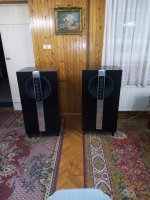
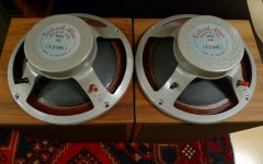
This story is for yet another highly overpriced old cd player, part of component system with beautiful look. Mirrors on front panels, fluorescent tubes, ....

I brought receiver and 2 cd players from this system few months ago. In attempt to impress, seller warned me: This system have the 'modern' sound! Didn't pay attention to his words because i do not believe in all those metaphors. First try at my speakers and surprise, no dynamic, no resolution, no high bands. Classic, symphonic orchestra, Manowar, Mettallica, whatever material i trow to it, no more than 2 minutes and i am forced to stop it. After ~20 minutes -> hard fatigue.

NO WAY, it was kidding with me! I like their outlook and don't want to throw them in recycle bin.

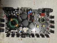
First i opened the receiver. Schematic is available online for few versions of it. Almost immediately it was fixed, at least to point which allows me to continue. In general, i liked what i found inside, didn't dig in details yet. Good transistor amplifier, good thermal design, more later.

Next, CD players. Little to zero technical info for them on internet. Few reviews, rarely alluding in half sentence potential sound problem. I was intrigued here.

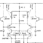
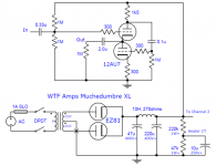
Seems there are at least 2 versions too. Some specs sites say it should contain 2xPCM1702-L (20 bit), but mine has 1xPCM1735E. Only empty holes on PCB for those PCM1702. Again, almost no info for PCM1735, except few other systems using it, and for them spec sites say 24bit dac. Didn't spy I2S to see what it is feed with, some not trustful sites mention mysterious ALPHA Denon proprietary sound processor in front of it for oversampling to 20 bits (for 2xPCM1702-L). After this dac i found SMD OP275 configured as Sallen-Key low pass with equal values and some small gain. 44kHz, 1.68 voltage gain, 0,757 Q. Again, empty slots for some other 2 SMD opamps. Nothing fancy, but very promising star.

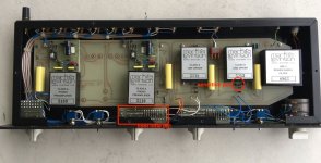
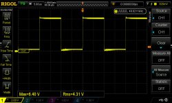
Quick measurements reveal one leaking (not shorted, just leaking) mute transistor, which resulted in reverse biased decoupling cap with ESR and voltage lost higher in decades. Around this cap i measured 9mV at opamp side and 2.5V at floating unit output (nothing connected to RCA)! Final decoupling caps was replaced with 2 reverse paralleled ones, transistors desoldered, very little improvement, if any at all. Wait what the *** is going here? Every element of the filter was checked and was completely OK. Get output directly after dac (using 150ohms stop resistors) and it shines. Ok then, at least dac is ok, let continue.

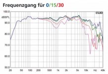
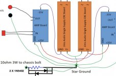
OP275 is powered by +8/-9V, with ~1-1.5V ripples at positive rail and flat negative! Ok, almost everything else is powered from 5V derived from it and that is the reason. But hey, this little chip is +/-22V one. It is undervolted very seriously, limiting its bandwidth and so on. Quick try with external PSU at +/- 15V proved that. Big difference. But, no suitable place to put third trafo inside the box! Difficult situation. Resolution: 2 half wave voltage doubler rectifiers, with 100uF pass,1000uF buffer caps and 4x1n4005 diodes, and single 470uF between rails. Ripples under 0.5V per rail, but absolutely symmetrical. 2 absolutely equal 17.5 volts. Big improvement in place, still dull sound for me.

What else can be wrong? Mute transistors are out, power for amp is ok, all elements are ok and within 5% range, or even 1%? What else? Wait, they put 680 ohm stoppers!?!? Usually not a problem, but not what i expect for source impedance. Quick swap with 100 ohms and Tha-Daaa. This little boy start to produce what it should at first place!

Great, now new muting transistors. But, there is something wrong (to my eyes). Regular NPNs, but with emitters to signal. Why? It is imperatively Denon decision to use such configuration in almost every system they ever made, seen very rare on other brands too. There are tons of reasons why not to use this configuration, from pure safety to killing actual signal quality! 2 garbaged 2N2222A, but with emitters pointing to GND -> no more pops and output quality is preserved.

Now this player plays very close to my main Yamaha RX-A1050 (to its 32bit sabre dacs) connected to external CD transport. For tests Denon is connected to analog input and transport is connected to coax spdif of this big boy, so same post processing, same power amp, same speakers. No ambitions to make them equal, actual achievement is more than i expected. Material investments was minimal, entirely from my junk box.

The lesson: Pay attention to small and unexpected things. They may made really big difference.

Now i will get back to the receiver to see what can be done with it.

Hope my story may help to someone else, as some or all of those errors are found in so many players, even in so called high end ones. Usual internet advises are in completely different ways, difficult to implement and with suspected outcomes.

EDIT: New power supply was added only for opamp. Everything else remains powered as before.

Mark Levinson 38 Preamp Schematic

I have in the workshop a Mark Levinson 38 preamp with odd fault. There is NO volume control even though the 'numbers in the display' change with rotation of the volume control or with the remote control. The output remains at a fixed level (high).
It does work when 1st turned on so I guess it is out with the freezer spray on the processor/surrounding caps etc.
Anyone experienced this problem?

DSP to kill room resonant modes

My main quest started with research on how to reduce the room resonant modes that cause muddy bass response. There is another subject thread here on the diyaudio forum that deals with solving that problem by careful positioning of the subwoofer in the room, and/or using multiple subwoofers in ideal positions to smooth the response. Reading that thread took me into a "rabbit hole" of dozens of other websites, tech articles, audio journals, etc on the subject. My conclusion is that none of them work really well. They typically only deal with specific frequency modes and their harmonics and work somewhat ok with either the even or odd harmonics but not both.

Since co-planar parallel room surfaces are responsible for the standing waves that cause irregular low frequency response I briefly considered re-modeling to move walls so that there are no parallel surfaces, and re-doing the ceiling to make a vaulted, sloped ceiling into the attic space above. The cost of doing that quickly killed that idea.

My next idea for eliminating standing waves was to completely eliminate the reflective surfaces, creating essentially an outdoor listening environment. Not too comfortable in inclement weather, nor courteous to the neighbors.

Bass traps/absorbers placed within the existing room were vetoed by the wife for aesthetic reasons.

Then, thinking the through the fundamental problem, which is sound waves reflecting off of surfaces, I concluded that signal level DSP (Digital Signal Processing) could be used on each loudspeaker channel to add in a delayed version that would null out the first, second, and perhaps third reflections from walls/floor/ceiling that reach my listening position, leaving the direct path to my ears as the dominant sound. Of course this would work only if my listening position and loudspeaker positions were constant. There would be a "sweet spot" at the listening position, but that spot would be bigger at lower frequencies where the wavelength is longer. An 11 ft wavelength at 100Hz should encompass a couple feet where the cancellation signals arrive without too much phase shift relative to the reflected signal. I'd certainly be willing to sit closely on the couch with my wife. I would offer the prime seat to a visiting buddy if he brought the beer.
Above 100Hz, the room itself is evenly reverberant and damped with furniture, carpet, and drapery. So DSP on the higher frequencies may not be needed. Perhaps the DSP on only a single subwoofer channel is needed. Stereo channels could be high pass filtered so their woofers do not add much to the low frequency room resonant modes.

I strongly suspect that this DSP method is not an original idea of mine. Surely it has been done before. So my questions to the forum group here are: Does this technology have a name? If I go into an audio equipment store and ask for _____ will the salesperson understand what I want?
Can you recommend products like this that are commercially available? I expect something should be out there for less than $500.

Thanks in advance.

Thermal Compression Design Guidelines

In a loudspeaker, power compression or thermal compression is a loss of efficiency observed as the voice coil heats up under operation, increasing the DC resistance of the voice coil and decreasing the effective available power of the audio amplifier
from Wikipedia

In addition, an increase in Re will:
  • Increase Qes
  • Decrease Qms
  • Decrease Qts (it depends on the relative size of Qes and Qms but I'm pretty sure Qts would decrease for almost all subwoofers).
  • Decrease efficiency
  • Decrease sensitivity

I noticed that these changes can strongly impact the behavior of my subwoofer at low frequencies in hornresp. For example, 20C of temperature rise caused my flat response that is within Xmax to change into a peaky response at 20hz that causes the driver to displace beyond Xmax.

What would be a design rule of thumb for taking into account thermal compression? How do I estimate a reasonable temperature rise above ambient?

Amplifier as Power generator example PS audio power plant

I didnt understand actually to which forum group it does it belong as does it comes to power supplies or amplifier forum because it generates sine wave power using an amplifier so i guess this is the right place to ask the question.

I saw the youtube video from paul from PS audio and found that the power regenerator is nothing but an amplifier with sine wave input with some variable. Please check the link given below.

YouTube

If i want a sine wave generation with out any PWM based sine wave generator can I use just an amplifier in either Class AB more or Class H mode in any one of it in bridge mode? basically how does this work as Im very curious about this power regenerator. Can any one explain how to do this with just using amplifier module? Considering 7 pairs of OPS transistor or may be 10 pair? What is the way to build a regenerator? Im guessing most of the loads are in less than 0.5ohms in the primary of the load. So does the amp be stable in that load as well? Some primary of the transformer in the load ( or equipment ) would it be consuming less current as primary resistance is higher? I would like to try the diy version of the power regenerator.

Sonotube Stiffness Along Axis of Cylinder

Hello All,

When making a Sonotube subwoofer of a given volume, lets say 200 liters you could for example:

  • use a 36" diameter sonotube which would result in ~12 inch tall
  • use a 24" diameter sonotube which would result in ~26 inches tall
  • use a 16" diameter sonotube which would result in ~60 inches tall

What factors would you consider to choose one of them if SQ was your only goal (not aesthetics, not practicality of placing in your room)?

ADAFRUIT AUDIO-FX

Hello to all .
I would like to ask you some information about the following device.
it is an audio file player: adafruit audio-fx.
Adafruit Audio FX Sound Board - WAV/OGG Trigger with 2MB Flash : ID 2133 : $19.95 : Adafruit Industries, Unique & fun DIY electronics and kits
https://cdn-learn.adafruit.com/downloads/pdf/adafruit-audio-fx-sound-board.pdf
I am interested in knowing what kind of quality its outputs possess, I have not found anything that can make me understand how they are made. I do not think it is HI-FI quality. from what I understand they are analog line outputs that go directly to the audio speakers.
do you think it is possible to bypass the outputs and go directly to an external DAC?

Subwoofer and linearity

Hello people,


I try to measure a subwoofer of mine in order to compute a linkwitz transform, and I am suprised to see that it is highly non-linear.


at 1Vrms, fs = 51Hz
at 5Vrms, fs = 41Hz
at 7Vrms, fs = 38Hz (!)
I didn't go any further.


39Hz is the value given by the manufacturer.
I measured that by holding the thing in my hand (but if it rests on the floor it only change fs by one or two hertz)


Is it normal such un-linearities at a rather small voltage?

Could it behave better properly enclosed ?It's a rather cheap car subwoofer, should I try to get a better one?


It is that one :

https://www.focal.com/sites/www.focal.fr/files/shared/catalog/document/fiche-technique-27v1.pdf


Thank you very much for your time, I hope you can enlighten me

UV lettering on Anodized Panels

I have been using laser engraving on black anodized aluminum panels with great success for many years. This looks fairly white with good contrast and is much better than inked milled lettering like Front Panel Express panels.

Silkscreening is not a great solution in my view.

I am now trying to find a good solution for anodized panels where the color is not black. In my case, I don't get a good enough contrast with the "bare metal aluminum" laser engraving. I have tried Birchwood Casey Aluminum Black which turns exposed laser engraving black and leaves the anodizing unchanged. This does turn the lettering black but it still could have much better contrast.

I have seen that Front Panel Express offers UV printing. Their panels are only really prototype quality since the have exposed edges.

So I have thought about whether UV printing on a flat bed printer might make sense. These vary considerably in price. I am not inclined to buy an expensive printer but a cheap version or maybe using a service bureau might be an option.

Does anyone have experience down this path?

Al

FYI AnTek AS-4218 (400VA, 18V) back in stock as of 9/16/2021

I e-mailed them and someone immediately replied and said they just got them, reloaded 50 units...now 49 because I ordered mine.

Also suggested the CA-400 was coming, but as of posting this don't see it restocked yet.

Mods feel free to delete if this doesn't belong here, but no idea how long this has been out of stock (with the world being a mess right now supply chain wise) and I've seen other people asking about buying this specific piece...looking for substitutes. This one is back.

Thanks,

Ken

My beloved Wavetek 166

I acquired my Wavetek 166 signal generator about 20 years ago. I really like knobs and have avoided digital for this reason.
It worked great for the first five then it went belly up. - no signal output. I use this generator frequently. I had transported it and it didn't travel well apparently.
I affectionately call this my "analog nightmare". It's design preceded all but the 741 op amp. There's a ton of discrete circuitry as a result.
The design concept is sound and used in many generators of that period. Essentially all waveforms are generated from a self oscillating triangle waveform generator circuit. A positive and negative current source pair alternately charge and discharge a selected capacitance. This results in a very linear ramp up and down at the frequency dictated by the current level and capacitance.
Anyway, there's a buffer circuit that follows the triangle generator implemented with a matched pair of FETs, a matched pair of BJTs, and misc components numbering in the neighborhood of 25. This circuit has been the bain of me.
I fixed it the first time by replacing the two seperate FETS with a dual matched pair package, 2N5564. I had to fly wire the second half to the land pattern of the second FET next to the first. This worked great for about 8 years of hard use.
It broke again lately. This time it puts out a distorted signal rather than none at all. The triangle wave looks scalloped symmetrically on the rise and fall.
It's black and white. The signal looks perfect before the buffer and distorted after. The triangle signal from the generator needs to be buffered by a very high input Z circuit hence it hits the gate of one of the JFETS. I replaced the matched pair again - no change.
After a ton of head scratching I decide to simulate it in TINA to get an idea what might be going on. It simulates great in TINA with expected result. However, it takes about 30 seconds of iteration to come with a DC operating point. This exercise yielded no fruit ultimately.
Hmmmm.... is the output of the buffer being overloaded?
Well, normally I would unhook the output to prove that. Unfortunately, the buffer is a part of a big loop and triangle circuit stops producing a waveform.
I replaced a few other transistors - no change. Replacing anything is quite difficult. To get to the solder side one must remove another board that covers up the board of interest. This includes removal of many knobs, etc. I suppose I could replace all components (25) comprising the buffer circuit. However buying enough transistors so I can match them seems insurmountable.
I threw my hands up and now have decided to build a buffer using a high speed JFET opamp and will splice it in. That's really quite simple now that High input Z, high speed, high V op-amps are available.
I'll let you know the results in a week or two.

Resistor size

I’m wondering why a 10k ohm 1/4 watt resistor is so much larger than a 3k3 ohm 1/4 watt? They are both metal film, one is dale and I’m not sure what the other is. Take a look at the picture and tell me what you think. These are both from mouser and the part numbers correspond to the part but Why the 3300 ohm is so much smaller than the 10k is odd, to me. I’ve got 18 ohm 1/4 watt that are physically bigger. What’s the deal?
Thanks

Attachments

  • 01092F26-C2B9-43E7-B293-97399C5D53B8.jpeg
    01092F26-C2B9-43E7-B293-97399C5D53B8.jpeg
    25.1 KB · Views: 162

Rockford T1500-1BD Power Problems

I have on my bench, one Rockford T1500-1BD (not T1500-1BDCP). It came in with blown output caps C2016 and C2017, C1015 (main rail cap) was bad, and low collector voltage on Q2010, and Q2012.

I replaced the output caps, the main rail caps, Q2000, Q2001, Q2010, Q2012, U2000, and U2002. I even replaced R2035 with a 1 Ohm resistor as the one that was there is getting super hot. I've yet to do the LM7815 trick that's listed in Perry's tutorial, but I'm just trying to get the amp up and running before I do it...

Now when I power the amp up, the rail voltage builds but does not make it to the output fets. Also the collectors of Q2010 and Q2012 start off at 22.39V but then drop right away to 9.25V. U2002 is heating up and R2035 feed drops to around 3.7V.

Upon my reading in these forums, it was said to replace U2002 and to replace the 74HC74 IC on the BD Output card.. I replaced all of this and the output fets do not get rail to rail oscillation and the gate legs do not get a drive signal.

I have attached the schematic that Rockford has supplied me upon asking - it doesn't include the BD Output Card (I've since asked for the schematic but no reply as of yet).

I have also attached photos of something I saw that was a bit strange - I'm assuming it's because the Q2010 and Q2012 isn't able to supply the 12V to R2035... But when probing the toggle A and B at the anodes of D2000 and D2017 I get different results. The anodes of D2000 have a nice square wave (around 50KHz), but the common cathode is basically DC voltage that sits around 6.4V. When probing D2017, on all pins I get a duty cycling square wave that sits around a volt or so.... When removing D2017, the toggle A and B pins match that of D2000, but the duty cycle on the common cathode remains. Also when removing the U2002, the R2035 voltages stabilize at about 11.38V. I've replaced U2002 again and the same thing happens. The collector voltage drops to about 9.28V on Q2010 and Q2012, R9 gets really hot, U2002 starts heating up, and C1015 starts getting luke warm.

Where do I look next, and what am I missing?

Attachments

  • 1405-52759-06-A SCHEMATIC MAIN.pdf
    1405-52759-06-A SCHEMATIC MAIN.pdf
    456.2 KB · Views: 175
  • Rockford T1500-1BD Mainboard.jpg
    Rockford T1500-1BD Mainboard.jpg
    892.8 KB · Views: 228
  • Rockford T1500-1BD - D2000 from LM5110.jpg
    Rockford T1500-1BD - D2000 from LM5110.jpg
    71.5 KB · Views: 146
  • Rockford T1500-1BD - D2000 marked A.jpg
    Rockford T1500-1BD - D2000 marked A.jpg
    71.8 KB · Views: 122
  • Rockford T1500-1BD - D2017 all pins.jpg
    Rockford T1500-1BD - D2017 all pins.jpg
    71.8 KB · Views: 145

Looking for woofer advice, 3/4 way high efficiency.

Hello.

Having a headache choosing woofers to complement what i already got, and i'd be thankful for some advice.
Shipping and import taxes on many of these makes me wanna do it only once instead of reselling and buying several times.

I got a pair each of the Bliesma T34A and B.
And a pair of B&W LF26751 FST 6 inch Mids, (220 ish FS,95 DB, 4 ohm, incredibly low distortion, and ca 1mm xmax)

Looking for quality woofers that can match up with what i got already. High efficiency, Low distortion, nice extended FR, and plenty of punch. Size and weight is not really of much importance (preferrably under 15 cubic feet though).

In need of covering 20-30 hz to 700-800hz.
The mid has a high FS/low xmax and im looking to use low slope x overs hence the high crossover point.

The strongest contenders so far 2x AE TD15S/H pr side if they can play clean that high, in a .5 config. Having a TD10M in beetween is a option ofc. But 2x15s already takes up a lot of height if for seated listening.
Alternatively a 10/12+18.

Currently running fully passive with a "intergrated amp" (2x280w@8 -> 2x1400W@1 ohm,1 400 000 µF of cap, in the 3 powersupplies)
But using a plate amp/dsp, dsp/biamping for the low end is possible, and maybe desireable.
And Making it a 3 way with a active bottom end is less of a daunting task to blend together well in the crossover.


Interesting drivers:
AE TD18H (The -F3 seems too high and in need of EQ on the low end)
AE TD15S
AE TD15H
AE TD12M
AE TD10M

TAD TM 1201 H
TAD TL 1801

BMS 18N862(More of a sub, and no efficiency to compensate for bsc,another candidate for eq/dsp only i guess)

JBL 2216ND-1

Eighteensound:
15NMB420 (needs some serious eq to do anything but midbass)
12NMB420
10NMB420

I've used some of the nmb420 series before and i found them good quality, sound and easy to work with.
The AE, TAD and JBL driver have limited info available in terms of spec sheets, off angle measurements etc.
So anyone that has experience with them, it would be appreciated with some input.
Looking for highest SQ and will be used for music 90% of the time.

Please review my cart before I order parts for my PSU!

My plan is to build diyA PSU with monolithic rectifiers and a 600VA 24v transformer.

I think this Mouser cart contains everything I need, minus the transformer and PCB. Please let me know if anything looks off or if I seem to be totally off the rails on my assumptions what I need 😛

Direct cart link: https://www.mouser.com/ProjectManager/ProjectDetail.aspx?AccessID=37d2997a84

Scroll "code" section to the right to see quantities and prices

Code:
[FONT="Courier New"][B]Part Number[/B]        | [B]Brand[/B]              | [B]Description[/B]                                                             | [B]Quantity[/B] | [B]Price[/B] | [B]Total[/B]
CL-60              | Amphenol           | Inrush Current Limiters 5A 10ohm Straight leads                         | 3        | $2.06 | $6.18
SLPX183M050H9P3    | Cornell Dubilier   | Aluminum Electrolytic Capacitors - Snap In 18000uF 50V 20% 85C          | 8        | $5.95 | $47.60
KBPC5010-G         | Comchip Technology | Bridge Rectifiers DIODE RECT BRIDGE 50A 1000V                           | 2        | $3.61 | $7.22
CPF322K000FKB14    | Vishay             | Metal Film Resistors - Through Hole 3watts 22Kohms 1%                   | 2        | $1.27 | $2.54
CPF31R0000FKE14    | Vishay             | Metal Film Resistors - Through Hole 3watts 1ohms 1% 100ppm              | 2        | $1.15 | $2.30
TLHG6400           | Vishay             | Standard LEDs - Through Hole Green Tint Diffused                        | 2        | $0.46 | $0.92
CPF3R47000JNB14    | Vishay             | Metal Film Resistors - Through Hole 3watts .47ohms 5%                   | 8        | $1.86 | $14.88
CCF0710K0JKE36     | Vishay             | Metal Film Resistors - Through Hole 1/4watt 10Kohms 5% Rated to 1/2watt | 2        | $0.13 | $0.26
1985852            | Phoenix Contact    | Fixed Terminal Blocks MKDSN 1.5/3 HT                                    | 2        | $1.64 | $6.56
62409-1            | TE Connectivity    | Terminals .250 PCB TAB                                                  | 8        | $0.14 | $1.20
MKP2D031001F00JO00 | WIMA               | Film Capacitors 0.1uF 100 Volts 5%                                      | 2        | $0.66 | $1.32

[B]Total $91.06[/B]
[/FONT]

Anyone built a PP-1C or PP-2C (Alan Wright designs)?

Hi,

I was looking the PP1 design at Schematics and I've also read about and found scematics for a newer KT88 based revision called PP-2C

I've seen threads here from people who were contemplating to build one of those but I have not found any actual stories of completed builds so far.

Did anyone here or someone you know build one of these and would be willing to share some expiriences, stories or pictures? That would be very interesting...

Cheers!
Lars

Does a high end capacitor on woofer improve sound?

To start I'm building a 3-way speaker using these drivers:

Tweeter: Sb Acoustics satori tw29txn-b
Midwoofer: Sb Acoustics satori mw13tx
Woofer: Sb Scoustics satori Wo24p

I've been going down the rabbit hole of how certain crossover parts could alter a speakers sound signature. My interest Is if anyone has observed a noticable change in sound by using different types/brands for a given crossover filter.

More specifically if a 2nd order low pass was used would using a high end capacitor but "worth" two, three, or more times the cost

PC speaker project

Hi,

Firstly I want to be clear that I am a complete novice with circuitry and electronics. I do have a healthy respect for electricity, and safety is always on my mind.

I had a mad idea to free up my Bose bluetooth speaker I've been using with my home pc so I can take the Bose back downstairs where it should live. I have some old Dell pc speakers but they're no longer working so I mused about how to replace them. I came across some old Hi-Fi speakers that would work well in my office, but being passive they'll need an amp.

The mad idea: I had an old Panasonic LCD TV ready for scrapping, and I thought "Why not take the amp and power supply out and make it into a speaker amp?"

That started me off, so I've now cannibalised the TV, and taken the boards out. I have the TV's service manual downloaded which tells me what the parts are.

So the issues I need to consider:

I'll need to create a line input, but the more I think about this the more I realise my knowledge limitations.

The TV volume would obviously be controlled by remote. I have also taken out the IR receiver, so could this circuit be used with a volume control?

Housing the amp. Is a wooden box suitable?

I'm not after anything high quality - that could be worked on once I have more experience, just something to listen to music whilst on the pc. I don't want to spend loads of money buying kits, I just want to learn how to do this and gain some satisfaction knowing I built it myself, with help obviously!

Apologies for the long initial post, and any pointers or advice to "Get out before you do major harm to yourself and your family" will be gratefully received.

  • Locked
XRK Imposters on AliExpress

Hi Folks,
It seems there are several products popping up on AliExpress under the “XRK” brand. It’s kind of flattering and funny, but a bit worrisome because I don’t know what they sound like or how good they are. Even the logo looks a bit similar. Maybe it’s pure coincidence? I don’t know.

Anyhow, just wanted to let you know that I had nothing to do with these products being offered in this way.

HTB1e5fdPVXXXXa6XVXXq6xXFXXXZ.jpg_640x640Q90.jpg_.webp

XRK E3 Mini Desktop Earphone Headphone Amplifier HIFI Digital Stereo Audio MP3 Amp with LME49600|mp3 amp|amplifier hifiheadphone amplifier hifi - AliExpress

There are more…

HTB11V6IboLrK1Rjy1zbq6AenFXay.jpg_640x640Q90.jpg_.webp

https://m.aliexpress.com/i/32977079729.html

HTB10qv5bjDuK1Rjy1zjq6zraFXaz.jpg_640x640Q90.jpg_.webp

https://m.aliexpress.com/item/32975...2g0n.store_m_home.smartJustForYou_830115793.0

HTB1MkRDPFXXXXbLXXXXq6xXFXXXs.jpg_640x640Q90.jpg_.webp

https://m.aliexpress.com/item/32794...2g0n.store_m_home.smartJustForYou_830115793.0

NAD transformer config for new Wolverine?

Advice needed - NAD transformer config for new Wolverine?

I am gathering parts to build the upcoming Wolverine and found a broken NAD t773 as a chassis and heatsink donor.

Trying to figure out if I transformers as well, and if so what configuration makes sense. Unfortunately I don't know the VAC on them.

The t773 is a 7x110, with 2 transformers. One runs 3x110 and some extras, one runs 4x110. Curiously, the larger 4x110 runs at 54-0-54v, the smaller at 51-0-51. They must drop a decent amount of voltage as power supply is just under 60 VDC.

Here are the options as I see:

1) use the 4x110 only. I think NADs ratings are a bit conservative and it was capable of higher peak power, so 2x200 seems reasonable.

2) use the two transformers as dual mono. As I understand the different voltage would only effect max potential output and I won't be near there.

3) scrap and get an appropriate, lower voltage transformer recommended for the build.


Note this amp will be driving 4-ohm speakers, though never at high volume.


Any advice on this one?

4x110 - 5 3/8" x 2 1/2"
3x110 - 5 1/8" x 2 1/2"

Attachments

  • IMG_20210804_073610188.jpg
    IMG_20210804_073610188.jpg
    608.2 KB · Views: 268
  • IMG_20210804_073622163.jpg
    IMG_20210804_073622163.jpg
    508.9 KB · Views: 249
  • IMG_20210804_073633973.jpg
    IMG_20210804_073633973.jpg
    650.2 KB · Views: 249

Maya R2R Advanced Volume controller

I still get emails from people interested in Maya, so here we go. Same prices as on the first GB.

Features:
- R-2R 64 1dB step attenuation
- Android/IOS client for remote control
- infrared remote RC5 protocol with autolearning
- infrared remote NEC protocol for Apple remote (default)
- OLED display
- 4 selectable inputs
- independent volume control for each input - very good for A-B source comparison
- extra low noise ground separation between digital and analog circuitry
- inrush current protection
- soft start with speaker protection
- soft turn off with speaker protection
- plate voltage delay for tube pre/amplifiers
- temperature display and monitoring
- temperature protection
- serial I2C bus for unlimited channel extension
- easy direct control and setup with precision optical encoder

Current firmware version is 0.9

More detailed information about Maya is available at vicol audio : MAYA - your ultimate volume-controller
An implementation from first GB Interest check on Vicol Audio Maya R2R Volume controller - Page 12 - diyAudio


Regards,
Tibi
Projects by fanatics, for fanatics
Get answers and advice for everyone wanting to learn the art of audio.
Join the Community
507,641
Members
7,882,254
Messages

Filter

Forum Statistics

Threads
405,945
Messages
7,882,254
Members
507,641
Latest member
Gousty