Hello guys.
This story is for yet another highly overpriced old cd player, part of component system with beautiful look. Mirrors on front panels, fluorescent tubes, ....
I brought receiver and 2 cd players from this system few months ago. In attempt to impress, seller warned me: This system have the 'modern' sound! Didn't pay attention to his words because i do not believe in all those metaphors. First try at my speakers and surprise, no dynamic, no resolution, no high bands. Classic, symphonic orchestra, Manowar, Mettallica, whatever material i trow to it, no more than 2 minutes and i am forced to stop it. After ~20 minutes -> hard fatigue.
NO WAY, it was kidding with me! I like their outlook and don't want to throw them in recycle bin.
First i opened the receiver. Schematic is available online for few versions of it. Almost immediately it was fixed, at least to point which allows me to continue. In general, i liked what i found inside, didn't dig in details yet. Good transistor amplifier, good thermal design, more later.
Next, CD players. Little to zero technical info for them on internet. Few reviews, rarely alluding in half sentence potential sound problem. I was intrigued here.
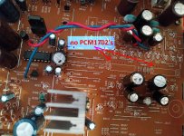
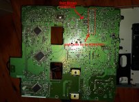
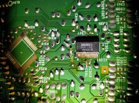
Seems there are at least 2 versions too. Some specs sites say it should contain 2xPCM1702-L (20 bit), but mine has 1xPCM1735E. Only empty holes on PCB for those PCM1702. Again, almost no info for PCM1735, except few other systems using it, and for them spec sites say 24bit dac. Didn't spy I2S to see what it is feed with, some not trustful sites mention mysterious ALPHA Denon proprietary sound processor in front of it for oversampling to 20 bits (for 2xPCM1702-L). After this dac i found SMD OP275 configured as Sallen-Key low pass with equal values and some small gain. 44kHz, 1.68 voltage gain, 0,757 Q. Again, empty slots for some other 2 SMD opamps. Nothing fancy, but very promising star.
Quick measurements reveal one leaking (not shorted, just leaking) mute transistor, which resulted in reverse biased decoupling cap with ESR and voltage lost higher in decades. Around this cap i measured 9mV at opamp side and 2.5V at floating unit output (nothing connected to RCA)! Final decoupling caps was replaced with 2 reverse paralleled ones, transistors desoldered, very little improvement, if any at all. Wait what the *** is going here? Every element of the filter was checked and was completely OK. Get output directly after dac (using 150ohms stop resistors) and it shines. Ok then, at least dac is ok, let continue.
OP275 is powered by +8/-9V, with ~1-1.5V ripples at positive rail and flat negative! Ok, almost everything else is powered from 5V derived from it and that is the reason. But hey, this little chip is +/-22V one. It is undervolted very seriously, limiting its bandwidth and so on. Quick try with external PSU at +/- 15V proved that. Big difference. But, no suitable place to put third trafo inside the box! Difficult situation. Resolution: 2 half wave voltage doubler rectifiers, with 100uF pass,1000uF buffer caps and 4x1n4005 diodes, and single 470uF between rails. Ripples under 0.5V per rail, but absolutely symmetrical. 2 absolutely equal 17.5 volts. Big improvement in place, still dull sound for me.
What else can be wrong? Mute transistors are out, power for amp is ok, all elements are ok and within 5% range, or even 1%? What else? Wait, they put 680 ohm stoppers!?!? Usually not a problem, but not what i expect for source impedance. Quick swap with 100 ohms and Tha-Daaa. This little boy start to produce what it should at first place!
Great, now new muting transistors. But, there is something wrong (to my eyes). Regular NPNs, but with emitters to signal. Why? It is imperatively Denon decision to use such configuration in almost every system they ever made, seen very rare on other brands too. There are tons of reasons why not to use this configuration, from pure safety to killing actual signal quality! 2 garbaged 2N2222A, but with emitters pointing to GND -> no more pops and output quality is preserved.
Now this player plays very close to my main Yamaha RX-A1050 (to its 32bit sabre dacs) connected to external CD transport. For tests Denon is connected to analog input and transport is connected to coax spdif of this big boy, so same post processing, same power amp, same speakers. No ambitions to make them equal, actual achievement is more than i expected. Material investments was minimal, entirely from my junk box.
The lesson: Pay attention to small and unexpected things. They may made really big difference.
Now i will get back to the receiver to see what can be done with it.
Hope my story may help to someone else, as some or all of those errors are found in so many players, even in so called high end ones. Usual internet advises are in completely different ways, difficult to implement and with suspected outcomes.
EDIT: New power supply was added only for opamp. Everything else remains powered as before.
This story is for yet another highly overpriced old cd player, part of component system with beautiful look. Mirrors on front panels, fluorescent tubes, ....
I brought receiver and 2 cd players from this system few months ago. In attempt to impress, seller warned me: This system have the 'modern' sound! Didn't pay attention to his words because i do not believe in all those metaphors. First try at my speakers and surprise, no dynamic, no resolution, no high bands. Classic, symphonic orchestra, Manowar, Mettallica, whatever material i trow to it, no more than 2 minutes and i am forced to stop it. After ~20 minutes -> hard fatigue.
NO WAY, it was kidding with me! I like their outlook and don't want to throw them in recycle bin.
First i opened the receiver. Schematic is available online for few versions of it. Almost immediately it was fixed, at least to point which allows me to continue. In general, i liked what i found inside, didn't dig in details yet. Good transistor amplifier, good thermal design, more later.
Next, CD players. Little to zero technical info for them on internet. Few reviews, rarely alluding in half sentence potential sound problem. I was intrigued here.
Seems there are at least 2 versions too. Some specs sites say it should contain 2xPCM1702-L (20 bit), but mine has 1xPCM1735E. Only empty holes on PCB for those PCM1702. Again, almost no info for PCM1735, except few other systems using it, and for them spec sites say 24bit dac. Didn't spy I2S to see what it is feed with, some not trustful sites mention mysterious ALPHA Denon proprietary sound processor in front of it for oversampling to 20 bits (for 2xPCM1702-L). After this dac i found SMD OP275 configured as Sallen-Key low pass with equal values and some small gain. 44kHz, 1.68 voltage gain, 0,757 Q. Again, empty slots for some other 2 SMD opamps. Nothing fancy, but very promising star.
Quick measurements reveal one leaking (not shorted, just leaking) mute transistor, which resulted in reverse biased decoupling cap with ESR and voltage lost higher in decades. Around this cap i measured 9mV at opamp side and 2.5V at floating unit output (nothing connected to RCA)! Final decoupling caps was replaced with 2 reverse paralleled ones, transistors desoldered, very little improvement, if any at all. Wait what the *** is going here? Every element of the filter was checked and was completely OK. Get output directly after dac (using 150ohms stop resistors) and it shines. Ok then, at least dac is ok, let continue.
OP275 is powered by +8/-9V, with ~1-1.5V ripples at positive rail and flat negative! Ok, almost everything else is powered from 5V derived from it and that is the reason. But hey, this little chip is +/-22V one. It is undervolted very seriously, limiting its bandwidth and so on. Quick try with external PSU at +/- 15V proved that. Big difference. But, no suitable place to put third trafo inside the box! Difficult situation. Resolution: 2 half wave voltage doubler rectifiers, with 100uF pass,1000uF buffer caps and 4x1n4005 diodes, and single 470uF between rails. Ripples under 0.5V per rail, but absolutely symmetrical. 2 absolutely equal 17.5 volts. Big improvement in place, still dull sound for me.
What else can be wrong? Mute transistors are out, power for amp is ok, all elements are ok and within 5% range, or even 1%? What else? Wait, they put 680 ohm stoppers!?!? Usually not a problem, but not what i expect for source impedance. Quick swap with 100 ohms and Tha-Daaa. This little boy start to produce what it should at first place!
Great, now new muting transistors. But, there is something wrong (to my eyes). Regular NPNs, but with emitters to signal. Why? It is imperatively Denon decision to use such configuration in almost every system they ever made, seen very rare on other brands too. There are tons of reasons why not to use this configuration, from pure safety to killing actual signal quality! 2 garbaged 2N2222A, but with emitters pointing to GND -> no more pops and output quality is preserved.
Now this player plays very close to my main Yamaha RX-A1050 (to its 32bit sabre dacs) connected to external CD transport. For tests Denon is connected to analog input and transport is connected to coax spdif of this big boy, so same post processing, same power amp, same speakers. No ambitions to make them equal, actual achievement is more than i expected. Material investments was minimal, entirely from my junk box.
The lesson: Pay attention to small and unexpected things. They may made really big difference.
Now i will get back to the receiver to see what can be done with it.
Hope my story may help to someone else, as some or all of those errors are found in so many players, even in so called high end ones. Usual internet advises are in completely different ways, difficult to implement and with suspected outcomes.
EDIT: New power supply was added only for opamp. Everything else remains powered as before.
Last edited:
Great, now new muting transistors. But, there is something wrong (to my eyes). Regular NPNs, but with emitters to signal. Why? It is imperatively Denon decision to use such configuration in almost every system they ever made, seen very rare on other brands too. There are tons of reasons why not to use this configuration, from pure safety to killing actual signal quality! 2 garbaged 2N2222A, but with emitters pointing to GND -> no more pops and output quality is preserved.
I have a suspicion that many muting transistors become damaged or impaired through 'hot swapping' of RCA leads, particularly on equipment that either has an SMPS and so could have quite high leakage currents or connecting to equipment that carries a high charge on any coupling caps... valve stuff perhaps.
The muting transistors may well be a 'special' type that have a rather unique property of having significant gain when used in a seemingly reverse biased state.
Have a look at the 2SC2878 data sheet as an example. These have a high 'reverse hFE':
2SC2878
Just different view point, not arguing in any way.
What about capacitance at emitter and collector? 10 times difference. Capacitance means reactance. I can hear you are arguing: they are in pF range. Yes, they are, this does not prevent distortion.
What about leakage currents at emitter and collector? Again big difference.
Everyday duty of muting transistors is in non-conducting state. in this state they operate (EC) at AC and eventually zero DC. in this condition there is no forward or reverse biased. In isolation every side can be represented as steady GND and other one as moving across it signal. Just different parameters make the big difference.
Perfect world replacement is simple relay.
Your suspicious are correct. What about distorting muting transistors put between input selector chip for example and power amp? or equalizer/volume chip and amp? It is not only for damaged ones, also perfectly working transistors can distort if used inappropriately.
That are my understandings and i can be completely wrong in them.
Respect
Reversed bi-polar transistors are often used where the extremely low V(sat) can be exploited.
Googling reverse V(sat) returns loads of links, but this quote sums it up:
"Invert the transistor and Vcesat reduces to about a tenth of its non-inverted value. An old time trick used before FETs became available."
The o/p seems, at least, to be quite competent in choice of forum name.")
Googling reverse V(sat) returns loads of links, but this quote sums it up:
"Invert the transistor and Vcesat reduces to about a tenth of its non-inverted value. An old time trick used before FETs became available."
The o/p seems, at least, to be quite competent in choice of forum name.
OP is right as capacitance is voltage dependent. It is an old trick but also a bad and cheap old trick to use bipolar transistors for muting. I removed bipolar muting transistors for years when possible. In many devices analog output stages this is clearly a positive difference but it is not always possible for instance in digital sources when an uncorrectable error occurs.
The test is simple and it can be quite convincing. It depends on type of transistors, values of series resistors and if they are used with C or E connected to the signal path. The later introduced special muting transistors were slightly better than the regular ones but for some reason they often failed. In short: for power on/off muting relays are the best choice but when the muting serves other purposes one better leaves the circuit as it is.
The test is simple and it can be quite convincing. It depends on type of transistors, values of series resistors and if they are used with C or E connected to the signal path. The later introduced special muting transistors were slightly better than the regular ones but for some reason they often failed. In short: for power on/off muting relays are the best choice but when the muting serves other purposes one better leaves the circuit as it is.
Last edited:
"Invert the transistor and Vcesat reduces to about a tenth ..."
cliffforrest, again, in ideal world at this position of muting transistors Vce can not be reversed. There is no such thing because they are exposed to pure AC. Reality is very close to this ideal, with some benefits if emitter points GND. Important working mode is in non-conductive region. Even in conductive one there are real benefits to orient them this way.
Just to add a bit for safety: usually those transistors become leaky in BE junction. Didn't see muting to be leaky in BC. Not that it is impossible, just i never see such. Also, they tend to short again in BE, not in BC. If emitter is connected to signal (with its high impedance), signal will be destroyed, or even worse, next unit will be overloaded. if emitter is connected to GND (almost ZERO impedance and endless current capability), signal remains clear and system is safe. Here I ignore EC failure with good reason. Transistors, as any other real element, are prone to failures of any kind and for any reason. Those transistors usually are last thing at unit output and there is nothing to safeguard after them. Why to impose entire system at risk if we can mitigate it that easily?
This amplifier (I also have one) was designed in an era when decent switching jfets were difficult to source for the price of an excellent bipolar like the workhorse 2N2222A.
ALL bipolars can be used in reverse mode, but the hfe is usually much less than one and the 6V Bvebo is also limiting so there is normally no advantage. A special case is to exploit Vec(sat) (ie reversed) having a much lower value than the Vce(sat). Effectively this means that the ON resistance is low ohms and can make an excellent attenuator with (say) a 20k source impedance.
Back in the day (I am ancient) I worked for Fairchild and we used reversed EC transistors as choppers in instrumentation amplifiers with great success.
I am hardly promoting this for new designs (there are many superb J and D FETS with very low on resistance) but hoped to explain why this was used. I have never experienced blow-ups, but maybe I am more cautious with age.
Last edited:
He he, I am a bit ancient too. 48 at the moment. My everyday job is not related to this kind of electronics.
For last time, in this concrete situation Vce = Vec.
And again, that is how I see the situation. I don't pretend to be correct.
I can happy accept few more milli volts at output during ON phase, but can't accept any signal degradation, especially if i can fix it for free. Switching speed is also not important here. May be slower switching is better, not sure?
FETs can add additional capacitance i will have to deal with later. 2 BJTs are cheaper than 4 FETs and need less space. For relay i have to look for suitable power line and where to fix it.
I shared my way of cheap fix of this unit (mainly manufacturer errors). It is not new design. What was interesting, at least for me, was contrary different approach i take, compared to normally advised ones, and exceptional results i get. It is shame to use all those good elements and to made those elementary mistakes. Such errors lead to what i call 'brand specific sound', which is actually a degraded sound.
I touch muting trans just because one of them was already faulty. Other vice i will not touch them at all. I bought this unit with already failed transistor. Dealing with those very small SMD ones is not a joy at the age of my eyes. The need introduced the chance to put them as i hope is better.
I know this thread is about 9 months old, but thought someone here may be interested in this.
I own the DENON DCD-201SA CD player. Recently I found a service manual for it and was most excited when I stumbled across it (I almost fell) on the Internet Archive database after months and months of extensively searching google.
The DENON DCD-201SA service manual (PDF):https://archive.org/download/manual_DCD201SA_SM_DENON_EN/DCD201SA_SM_DENON_EN_text.pdf
The webpage it comes from:Manual: DCD201SA SM DENON EN : Free Download, Borrow, and Streaming : Internet Archive
The manual quotes the Burr Brown PCM1735E DAC, but sadly does not contain any information about it.
This all started some months ago when I had to remove the cover to replace a drive belt. I was perplexed when I found no PCM1702 DAC's!! As this is what I knew it had, well at least till that moment. I then decided to remove the main PCB, which I had found and single chip DAC, PCM1735E on the under/copper side. Strangely no datasheet seems to exist anywhere for it anywhere. From my findings it appears to be a 24-bit DAC.
If anyone has any info on it I would be more than appreciative in knowing.
Attachments
- Home
- Source & Line
- Digital Source
- Denon DCD-201SA, or how small things can kill everything