Hi,
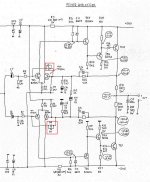
I would like to know what is the purpose of these diodes (CR7/CR8 and CR9/CR10) connected this way in the attached schematic.
Attached here are: full schematic of the SUMO Andromeda2 amplifier (PDF file) and a screen capture (PNG file) where diodes (CR7/CR8 and CR9/CR10) are boxed in red for easy location on the schematic.
I am restoring an old Musical Fidelity A1 amplifier and found the same diodes configuration than on the Sumo. I replaced the diodes by a wire and found no changes in the amp behavior.
Any info would be highly appreciated,
Vince
Attachments

I have an opinion, but I could be wrong. The function of these diodes could be to limit the voltage difference between the collectors of Q3 / Q4 and Q5 / Q6 to prevent this difference from becoming dangerous for the bases of the transistors of the next stage Q7 / Q8 and Q9 / Q10. The insertion of resistors between the collectors and the bases of the next stage would have the same result, but by altering the bandwidth towards the very high frequencies.
Perhaps to prevent reverse biasing the Vbe junctions of the next stage during power-up and power-down transients? Such reverse biasing can damage a transistor easily, but also can greatly increase noise in the device semi-permanently.
In model MF A1 I would expect full level oscillation.
Schematic here : https://www.diyaudio.com/forums/solid-state/275272-issues-musical-fidelity-a1.html#post4495807
Note that the diodes are in input base circuit here.
Schematic here : https://www.diyaudio.com/forums/solid-state/275272-issues-musical-fidelity-a1.html#post4495807
Note that the diodes are in input base circuit here.
Last edited:
Thanks for your replies, I will have a look in details.
@ as_audio: During my MF A1 restoration I faced some oscillations but they disappeared one day I cannot say what I have done exactly. I replaced the diodes with a wire and presently the restored MF A1 works fine.
I attached here the MF A1 schematic, you are right to point out that the diodes are in base circuit instead of the collector circuit like in the Sumo. I do not know if those diodes are the culprit but some components of one channel of my Sumo got fire (flames & sparks) when I tried to fix it a long time ago. Surely very high level oscillations.
Vince
Attachments
We should clearly decide to talk about Sumo or MF A1, but not mixed or in a single post.
These two amp concepts have "nothing" in common. Also repair requirements will be different.
I can not believe that A1 amp works if you connect the bases of pos and neg input - check again.
These two amp concepts have "nothing" in common. Also repair requirements will be different.
I can not believe that A1 amp works if you connect the bases of pos and neg input - check again.
They often have diodes like that inside op amps.
I think it is to stop latch up.
It stops input voltages being too far apart.
I think it is to stop latch up.
It stops input voltages being too far apart.
In my opinion, replace the diodes by a wire simply set to 1 the gain of the differential stage TR3-TR4. May be it's a good idea, may be no. Reducing the gain can stop an oscillation, but it probably doesn't improve the quality of the amp. Fitting the diodes in their place and then looking seriously for the cause of the oscillation seems to me to be a better option. Do you have an oscilloscope? If yes, i can help you.Thanks for your replies, I will have a look in details.
@ as_audio: During my MF A1 restoration I faced some oscillations but they disappeared one day I cannot say what I have done exactly. I replaced the diodes with a wire and presently the restored MF A1 works fine.
I attached here the MF A1 schematic, you are right to point out that the diodes are in base circuit instead of the collector circuit like in the Sumo. I do not know if those diodes are the culprit but some components of one channel of my Sumo got fire (flames & sparks) when I tried to fix it a long time ago. Surely very high level oscillations.
Vince
Post 1 (MF A1) : "I replaced the diodes by a wire and found no
changes in the amp behavior."
My post 5 : "In model MF A1 I would expect full level oscillation"
<add to this "if you replace the diodes by a wire">.
Only after that OP talked about spurious oscillation.
I do not agree with your post 9 because coupling of positive and
negative inputs can not lead to a working amplifier with "no
changes in the amp behavior" (post 1 again).
OK
I'm sorry, my English is not very good, but I quite agree: coupling the inputs of a differential does not make sense. Reporting this fact, but with moderation was the purpose of my comment.
I'm sorry, my English is not very good, but I quite agree: coupling the inputs of a differential does not make sense. Reporting this fact, but with moderation was the purpose of my comment.
Hi,
It is not necessary to make separate sumo and MF A1 posts because I took the chassis of the sumo to install something else inside. I definitely could not fix it.
For the MF A1, I remember I did connect a wire instead of the diodes during my restoration work. But there is no wire instead of diodes now.
I am so sorry for the confusion, what I wanted to tell in my post is that with or without those diodes the amp works fine, so what is the purpose of them. That was the reason why I posted.
I have an oscilloscope and tried to observe if there is any difference at the output with or without those diodes but I observe nothing.
Vince
- No, the MF A1 amp can not work with these diodes shorted.
- Original question, applies to A1 and Sumo, the diodes shown
aim to prevent overdrive / saturation inside the feedback loop.
- Original question, applies to A1 and Sumo, the diodes shown
aim to prevent overdrive / saturation inside the feedback loop.
Those are protection diodes (limit signal peaks available driving next stage)I wanted to tell in my post is that with or without those diodes the amp works fine, so what is the purpose of them. That was the reason why I posted.
I have an oscilloscope and tried to observe if there is any difference at the output with or without those diodes but I observe nothing.
You "see no change" ONLY because in normal operation 700mV peak is not reached.
Same as any protection circuit, they "do nothing" if not triggered or threshold not reached.
Consider a power amp with/without short circuit protection: will work exactly the same ... until output is shorted.
One will release magic smoke, the other will not ... guess which is which.
Or mains fuses: you can replace rated 1A by a 20A one pulled from your car or a roll of aluminum paper, amp will "work the same".
Until ...........
Exact
Very just.
During my ten years working at Philips, I have learned that:
For the manufacturer to accept the additional cost of manufacturing a protective circuit, there must be a good reason.
This reason is usually the cost of warranty repairs.
That's why good technicians always follow the schematic if possible.
Hi,
I Agree. Equipment makers always want to reduce cost and they would not put components if they do not serve.
I believe from the beginning that these diodes are there for some protections concerns. But many amplifiers schematic have differential input stage but they do not have these diodes protection circuit why I found them in these 2 amps? Is there something special with them that require additional protections ?
From your replies I see that I do not have to worry too much about and the MF A1 will not take fire (it heats a lot) as my sumo amp. I will put these diodes back in the circuit when I have learned enough about the amp behavior.
Thank you to you all for your information, sorry for my bad question formulation and confusion.
Vince
Last edited:
I don't know any more about this question than you.
But I'm willing to bet that these two diodes were added during production due to a high number of warranty returns of devices with an important noise or distortion problem, due to damages in the base/emitter junction of some transistors, after reverse overvoltages.
During my professional life, we used to call this modifications "a posteriori" to the original schematic "add a wart".
Good luck and enjoy!
- Home
- Amplifiers
- Solid State
- Schematic question