Pleasant Edcor surprise!

I can’t believe it! I ordered a pair of Edcor GSE15 5K-8 transformers of the 26th of this month and they arrived today! I was expecting a two month not two week delivery time. I’ve heard everyone complaining about it. I’m thrilled. Maybe they have ramped production back up. I hope so for all involved. Nothing worse than waiting on one part to finish a project.

FS: Books: Morgan Jones, Douglas Self, Bob Cordell

I have the following books for sale:

Bob Cordell, Designing Audio Power Amplifiers, 1st edition, $39 SOLD
Morgan Jones, Valve Amplifiers, 3rd edition, $39 SOLD
Morgan Jones, Building Valve Amplifiers, 1st edition, $19 SOLD
Douglas Self, Audio Power Amplifier Design, 3rd edition, $39 SOLD

All amounts in USD. I can take payment by PayPal or credit card. I'll pay the fees. Shipping is extra, though.

The books are in excellent condition. They may have slight shelf wear, but it's very slight. They are completely free of notes, dog ears, stains, or any other nastiness. I did write my name on the inside title page of Doug Self's book, but that's the only book that's marked.

I'm only selling these because I have subsequent versions of them and am preparing to move this Spring.

I get excellent rates both with Canada Post and with FedEx/UPS. I can ship to the US and Canada for about $20 (up to two books, slightly more if you want all of them). Please contact me for the exact shipping rate to your location. I ship world wide.

You can reach me by email (preferred). Just take my user ID here and add @neurochrome.com. Alternatively, toss me a PM.

Tom

Attachments

  • Cordell_Front.jpg
    Cordell_Front.jpg
    186.8 KB · Views: 386
  • Cordell_Back.jpg
    Cordell_Back.jpg
    316.7 KB · Views: 374
  • Cordell_Inside.jpg
    Cordell_Inside.jpg
    239.5 KB · Views: 383
  • Jones_Front.jpg
    Jones_Front.jpg
    186.8 KB · Views: 382
  • Jones_Back.jpg
    Jones_Back.jpg
    223.8 KB · Views: 382
  • Jones_Inside.jpg
    Jones_Inside.jpg
    189.3 KB · Views: 71
  • Jones2_Front.jpg
    Jones2_Front.jpg
    192.9 KB · Views: 85
  • Jones2_Back.jpg
    Jones2_Back.jpg
    199.5 KB · Views: 90
  • Jones2_Inside.jpg
    Jones2_Inside.jpg
    175.5 KB · Views: 77

Laser Replacement VRDS 10

Hello, Fellas. I've just had to replace the laser assembly in an old Teac VRDS10 (original) and it still won't read discs. I've tried to tweeak the settings using the potentiometers on the servo board to no avail. Sometimes the disc will spin and stay spinning for a few seconds while the laser tries to tead the TOC (then stops) and sometimes the disc will not spin at all.
Has anyone had to set up a player from scratch and knows what those (5) pots do? They are labled 'F-Gain', 'T-Gain','S-Bal', 'T-Bal' & 'F-Bal'.

The Teac uses the same transport as some Copeland, Wadia and Krell players, and the same laser as some Denon and Sony units. If you have one, maybe you can help.

Cheers, Dan.

Attachments

  • teac innards1.jpg
    teac innards1.jpg
    73.4 KB · Views: 736

HexFet Amp Based on Philips AH578 and LMK

Within last 2 years,I built several amps based on the LMK (Lomakin and Parshin) design, described in this thread.
I also built amp based on Philips AH578, which has this advantage (?) that it has symmetrical VAS (push-pull), and higher slew rate.

This amp here is supposed to combine both designs into one.
My primary objective was to built symmetrical (and faster) LMK amp, but either I couldn't make them stable, or their parameters were not satisfactory.
This one seem to be ok ,at least in the sim.
As usual (for LMK/Wiederhold amps from 'Unusual amp thread'), there is an op-amp at the input.
Any feedback or suggestions for improvement?
Screenshots for Thd and FFT are for 1kHz and for 20kHz.

Update 30 Aug 2021:
Actual amp has been built and tested.
Schematic attached to the 1st post is outdated.
Final, the most up-to-date schematic in the post #111.
PCB1: post #123
PCB2: post #109
Update 07 Sep 2021:
Final and completed amp - post #126.

Attachments

  • phillips.lmk.jun20.hex.jpg
    phillips.lmk.jun20.hex.jpg
    295.9 KB · Views: 1,408
  • 1kHz_Thd.png
    1kHz_Thd.png
    24.6 KB · Views: 1,531
  • 20kHz_Thd.png
    20kHz_Thd.png
    25.3 KB · Views: 1,269
  • fft_1kHz.png
    fft_1kHz.png
    25.3 KB · Views: 1,243
  • fft_20kHz.png
    fft_20kHz.png
    25.9 KB · Views: 1,203
  • open_loop_margin.png
    open_loop_margin.png
    54 KB · Views: 284
  • clipping.png
    clipping.png
    24.1 KB · Views: 423
  • phillips.lmk.jun20.hex.asc
    phillips.lmk.jun20.hex.asc
    16 KB · Views: 171

LTspice models for Sanken 2SC3264/A1295

I made these models partly to test out some changes I've made in how I go about creating models.

Note that the 3264/1295 are the same chip as the 3263/1294, just in a different package. The MT-200 versions are typically unobtanium.


.model 2SC3263-Y_kq npn ; Revision 4 by keantoken - Feb 27 2019
+ Bf=84 Vaf=150 Is=1.8p Cjc=600p Cje=15n Tf=2.2n
+ Rb=.22 Rbm=0 Irb=200m Re=38m
+ Rc=1m Rco=750m Vo=1000 Gamma=24n Qco=100p quasimod=1
+ Br=8 Ise=16p Ikf=1000 Nk=0.2
+ Itf=10 Xtf=100 Vtf=0.8 Xtb=1.4
+ Vceo=230 Icrating=15A mfg=Sanken
.model 2SA1294-Y_kq pnp ; Revision 3 by keantoken - Feb 27 2019
+ Bf=90 Vaf=150 Is=60f Cjc=1.2n Cje=20n Tf=3.9n
+ Rb=1.4 Rbm=0 Irb=3 Re=33m
+ Rc=8m Rco=380m Vo=1000 Gamma=160p Qco=100p quasimod=1
+ Br=8 Ise=0 Ikf=22 Nk=0.5
+ Itf=10 Xtf=100 Vtf=0.8 Xtb=1.7
+ Vceo=230 Icrating=15A mfg=Sanken
.model 2SC3264-Y_kq npn ; Revision 4 by keantoken - Feb 27 2019
+ Bf=84 Vaf=150 Is=1.8p Cjc=600p Cje=15n Tf=2.2n
+ Rb=.22 Rbm=0 Irb=200m Re=38m
+ Rc=1m Rco=750m Vo=1000 Gamma=24n Qco=100p quasimod=1
+ Br=8 Ise=16p Ikf=1000 Nk=0.2
+ Itf=10 Xtf=100 Vtf=0.8 Xtb=1.4
+ Vceo=230 Icrating=17A mfg=Sanken
.model 2SA1295-Y_kq pnp ; Revision 3 by keantoken - Feb 27 2019
+ Bf=90 Vaf=150 Is=60f Cjc=1.2n Cje=20n Tf=3.9n
+ Rb=1.4 Rbm=0 Irb=3 Re=33m
+ Rc=8m Rco=380m Vo=1000 Gamma=160p Qco=100p quasimod=1
+ Br=8 Ise=0 Ikf=22 Nk=0.5
+ Itf=10 Xtf=100 Vtf=0.8 Xtb=1.7
+ Vceo=230 Icrating=17A mfg=Sanken

These models were fitted mainly to the Ic vs Vce chart, which includes quasi-saturation and gives better overall accuracy even though the fit to the Hfe vs Ic chart may not look excellent. The fact is a model that fits the Hfe chart perfectly is actually likely to be a poor model overall.


Apparent deficiencies of these models:
Hfe is too high in high-current deep saturation, as the Vo parameter seems to be doing the opposite of what it should. Hence Vo has been made too high to interfere.
Vaf (Early voltage) is not accurate. It is a best guess as there is no data.
It's been suggested that Rb/Re/Rc are incorrect even though I got the best fit to the data with the current combinations.
Qco determines the slowdown due to quasi-saturation, but I don't know the best way to determine this parameter. So I've set it to a low value, which will in theory be better than not at all.


I can improve the model if someone can take measurements:

Cbe and Cbc values, and perhaps at multiple bias levels.
Vaf measurements as the current values are are only educated guesses.

8600s voltage help

Hopefully someone can help. I recently built the 8600s with lundahl transformers. And it sounds fantastic. However, in my right channel the voltage starts out spot-on but then starts to vary. For example:

after 30 minutes.
TP3 101.1
TP4 109 one time then 29. Very strange
TP20 113
TP24 113
TP28 16

I quadruple checked the component placement and it lines up.

In addition, had an issue with one of the PCs 201 or 202 that the instructions indicated to put it one way and pages 22, the pcb chart, said another way - I put it the way on page 22 but maybe that isn't correct.

I checked the soldering but will check my solder on tube v1 pin 1, and PC202, and v4 tube pin 2?

Any advice would be appreciated.

Parasound PLD 1100 need burned trafo fix sollution

Hello, honorable forum group. This is my first post, so I bow my head to you. As usual, I registered here to look for help in the problem that touched me and it is so difficult to solve that I need help of kind people and good audio professionals. So to the point - I'm happy owner of the Parasound PLD 1100 preamplifier, which unfortunately has failed. The problem started a few months ago with minor ailments in the form of quieter operation of one channel after warming up of the unit. The equipment went to the local service for inspection but this did not say anything. Just after receiving the PRE from the "review" for a few days it was OK. Then, unexpectedly, the equipment stopped working - first I checked the fuse above the power socket on the rear panel and it turned out that it was burnt. After putting on a new one and connecting it to the mains it was OK again, but only for 1 day because after returning from work next day I felt an unpleasant burning smell and immediately thought that something was wrong. Of course, my intuitions turned out to be right - unfortunately the transformer burned in the PLD 1100 :-(. I really want to save this unit, but I don't want to incur the cost of buying a new ori transformer because its cost with the replacement service exceeds the value of the equipment itself on the secondary market. My electronics engineer suggested that he will repair this transormator or select another one from the local market in Poland, but he must know the voltage parameters on the secondary side of the transformer in order to match the replacement that would be made by one of the local companies specializing in such services. Unfortunately, there is no information in the manual or service diagrams that I need to save the equipment so that it can continue to serve me and enjoy my ears. If someone has such a unit and can take measurements, I will be very grateful for Your help. With it I will be able to save this noble preamplifier. Please let me know if anyone is able to help with this problem.

Suggestions/thoughts on my next project

Last year I built the simple Alpair 12.2p Small Reflex designed by Scott and absolutely love the sound, especially the detail. I'm currently running these near-field as a computer setup powered by a headphone amp, 0.5W max and it's just beautiful!

I'd like to expand on this and build something a bit different for my listening room and was thinking of another design by Scott, the Cape-Buffalo-Twin with two CHR120s per enclosure. I'd probably pair these with an Amp Camp which I already have.

I also considered the Seas A26, but in my very limited knowledge I *think* i'd prefer Scott's Twin Alpair. I don't have any firm requirements, a touch more low end over the 12.2p perhaps, listening volumes will be in the relaxed level.

Does this sound like a reasonable progression? I've attached the Buffalo Twin datasheet for reference.

BR

Attachments

  • Cape-Buffalo-Twin-CHR120-classic-vented-box-standmount.png
    Cape-Buffalo-Twin-CHR120-classic-vented-box-standmount.png
    98.7 KB · Views: 193

Any 5" to 7" mid/midwoofers using an inverted surround?

I am looking to test out drivers in the 5.25"-7" size class that use an inverted surround. The only drivers I am aware of are the Audax HM130C0/HM170C0.

Can anyone suggest others?

The next best thing would be a flat surround. For example there is the 6.5" Audax PR170M0 and the recent SB Audience Nero-6MRN150D 6" Midrange. Anything else like these out there?

Modding a Davis Model 106 P.A. Amp....

Good evening all~ I just came into this cute little amp, & after much searching online for possible & necessary alterations to make this a guitar growler, but could come up w/only this schematic,
Having my tech just do his thing & not take it further than simply functioning well, is like bringing a Harley to a lawn mower repair guy. Is it possible for some of you kind folks to chime in with 'must do' value alterations to make this 2xEL84, EZ81, 6EU7 into a little monster.... Would immediately having him wire it for a 12ax7 or the gainy & popular Vox EF86 preamp tube be a good start? Then, what more could be swapped out for different values to make it into a guitar or harp that screams, & something more suitable for RnR than playing my dad's olde '78's through. I realize it might sound like a heap of work for ya'll, but I only know basic electronic & can follow a schematic, but have never done it myself,,, I simply want to hand it over to my tech, as I'm just an end user.
Enclosed is a chassis shot & an original schematic for you generous consideration...
Thnx in advance~

Attachments

  • Screenshot_20211103-183613_Gallery.jpg
    Screenshot_20211103-183613_Gallery.jpg
    330.9 KB · Views: 139
  • 20211103_182147.jpg
    20211103_182147.jpg
    832.6 KB · Views: 160

TAC TAC noise in high gain mode

Hello,
i've made several tube amps, with a clean and a dirty channel, and when in high gain, there is a TAC TAC noise, it's dry and trebble sensitive, a TAC every 1.5 / 2 secondes. I used different diodes for the bridge, 1N4007 or faster diodes (UF something).
It gets louder with the gain and trebble...
ANy idea to understand, and maybe solve it?
Many thanks

Carver M500 power amp start up problems.

Hi

I could use some help from Carver experts.

I own a Carver M500 power amp and a Carver M500T power amp. The M500 is working and I have just repaired the M500T. Both are 120volt models. The working one I use with a 1000VA step down transformer that weighs 10kg.

I tried starting up the M500T that I had repaired on a variac for safety. It is a Claude Lyons high quality variac that weight 8kg and is 1200va.

The M500T emitted squealing noises as I increased the variac voltage over 60 volts. I tried a few times; always with the same result. I then tried the working M500 power amp. To my surprise I got squealing noises form that also. ( However this power amp is definalely working OK when used with a a step down transformer ).

Does this mean that I can not use a variac to test start a carver power amp.

NOTE; Yes these are magnetic field carver power amps. Possibly the triac does not like the varying voltage of the variac - any comments anyone?

Thanks in advance for any help or advise

Don

Totally solder-less amplifier kits?

Hello Mr. Nelson Pass.

I have been watching a few of your interviews and looking at your amplifier designs. Really liked your videos and views.

As you know, however, I have been experimenting with a simple class A amplifier - solder-less, all with wires and block connectors.

I do no think that I could ever build the PCBs and perform the soldering required for your kits in their present form.

Would you ever consider designing a solder-less amplifier design and offering it as a plan or a kit? That would make life easier to many people. You may, however have some concerns about sound quality and reliability.

Surprisingly, there are some enthusiasts out there who use crimped connectors and terminal blocks for their amplifier builds.

This builder has used solder-less connections extensively in his amplifier build.

https://www.diyaudio.com/forums/construction-tips/373042-tips-building-simple-alu-2.html#post6757520

There is a thread that looks at this concept here:

https://www.diyaudio.com/forums/tubes-valves/305115-solder-less-amplifier.html

I think I could manage to put together the Zen design linked above if it was solder-less but I would like to have a 18V DC input, have it run off a laptop power supply, and be content with 1 Watt output. I think your amp camp amplifier uses 19V.

So, what do you think?

Binary Mike

Member Binary Mike passed away earlier this year, after a long battle with cancer.


Mike got his start in electronics as a child. He scrapped old TVs and radios for parts to build and experiment with. As a teenager, Mike already knew how to design with vacuum tubes. He dropped out of his EE program in college because it wasn't challenging and moved too slowly.


Mike and his wife operated an AV repair business for many years and eventually transitioned to design of industrial video equipment. They operated this business until they learned of Mike's illness.


Binary Mike had always wanted to design tube amplifiers in his retirement. We are happy that he was able to spend several years engaged in this pursuit before he passed.


Those who really knew Mike knew him as an old soul; kind, patient, and wise beyond his years. By the time of his death, Mike's mastery of the art of electronics was so complete that it wasn't enough to simply design world class tube amplifiers. He had to spice up the task with extra challenges, like getting high-end sound quality from commodity components. He wanted to reduce the financial barrier to entry into audiophilia. His designs reflect both his expertise and altruistic tendency.


Rest in peace, Mike. We are poorer without you.
  • Like
Reactions: bondini

Do 16 ohm loads present any particular challenges to amps?

Since 16 ohm loads demand less power than 8 or 4, it seems like any amp that could do 8 ohms could deliver at least as much power into 16. Are there any other factors I’m not aware of that would affect this?

As a related question: If a speaker varies between 4 and 16 ohms over the frequency spectrum, would wny amp that can deliver sufficient power at 4 ohm be appropriate? What if it’s a tube amp? Would it need to have an autoformer output?

QCC3008: Enable i2s Output?

(posted here because i could not find a forum for Bluetooth)

We're trying to get i2s output from the QCC3008. We can see analog output, but we don't show any i2s output.

We used the ADK Config tool to apply the following:

Configuration Set:
- Audio:
- I2S:
- BPS: 16
- Resample rate: 48 kHz
- Voice: 48 kHz
- Bit-clock scaling: 32
- Output > Channel Allocation:
- Main Group Primary Left and Right: Hardware Endpoint Type: I2S

We tried to pull pin 29 SPI-PCM# low with a 1 kOhm and a 10 kOhm R, but neither worked. We noticed the pin is still high: we measure about 1.5V on that pin with a 1kOhm pull down to ground.

We're using an off-the-shelf QCC3008 module.

Weird LTP issue

Greetings all,

I'm finishing an amp with an LTP made of ECC88 cascodes. There's a CCS in the tail, with a 500 Ohm balance pot between the cathodes.
I was adjusting the balance with my scope and a 1 kHz sine. Right channel went fine, identical sines on the scope, top anode voltage on both sides 80V (B+ = 300V)
Left channel, same sines, nice. Top anode voltage 80V on one side, 230V on the other!?!
I blamed the tubes, swapped a few, but I still get the same result.
Cathode voltages are all in the same area.
I have NO idea what's going on, I hope someone can shed some light on this?
The amp seems to work fine, but this just seems wrong.
Thanks in advance.

Ak4499 noise at iv opamp output

I have a Gustard A18 and had been playing with different opamp for the IV. The original lme49860 actually sounded quite good with a thick warm sound as compare to my other Topping es9038pro dac but not as detailed. So I want to see if there are better opamps. First to try was opa1656, didn't work, sound too sharp. I measure iv opamp output with a cheap dso scope (can only do min 20mv and 1uS) and saw a huge amount of noise 38mV at around 1.3mhz. Next tried ada4610, much better but still have 7.2mV at 1.2mhz.
Next is opa1612, very similar to ada4610.
Just wonder if the noise at the iv opamp has any meaning and should I play with the 180pf IV filter cap to lower the noise?

Attachments

  • IMG_20200925_020426.jpg
    IMG_20200925_020426.jpg
    983.7 KB · Views: 662
  • IMG_20200924_175909.jpg
    IMG_20200924_175909.jpg
    600 KB · Views: 663

Need help fixing an off 'pop'!

Hi there!

I have some very basic electronics knowledge, but can't work out how to fix a problem I am having.

I put together an amplifier (based off a d-class AA-AB32189). It is powered off its own 36v dc transformer, and there is a second transformer powering a pre-amp and an input selector (for Bluetooth and 2x rca - one off to a phono pre-amp). I have just sketched up a very basic map of the setup and will attach bellow.

There is also a wifi switch in-front of the two transformers that I can use my google assistant to turn the unit on and off.

I love the system, it works and sounds great. However, I get a loud pop a few seconds after turning it off. I have a work around with a switch that I can use to turn the amp off first, then shut the rest down. But this kind of ruins the point of the Wifi switch as I still have to go to the unit to turn it off!

I am looking for a solution to fix this pop. I assume it is from the other circuits (preamp and selector) turning off before the amp, so need a way to either delay these units turning off by 2-3 seconds so the amp can go off first (some kind of large capacitor?) or by instantly muting the amplifier when the power is turned off.

The amp has an input for a mute switch, so I was thinking if there was a way that this switch could be triggered by the loss of the 240v ac coming out of thew wifi switch this could work?

I have read an easy solution can be a cap on the amp which drains it so it shuts down quicker, but not sure If i can add this to a D-class amp?

Sorry if this is convoluted, but I would really appreciate some help on how to overcome this ! I have read a few thing but not found a solution that makes sense. And I dont know how I can get the loss of AC to trigger a small on of switch (I know relays can trigger 240v via 12v but can they go the other way?)

Thanks in advance!

Attachments

  • map.JPG
    map.JPG
    27.8 KB · Views: 111

Use of the ECC88/6922/E88CC

Hi All,

I read somewhere that these tubes are designed for cascode use and that each triode in the envelope has slightly different parameters, particularly the max allowable Vhk.

However, I have been unable to confirm from this from any datasheets. With the possible exception of a a slight difference in some of the interelectrode capacitances, I can't find any mention of different parameters for each triode.

What, if any is the difference between the two triodes in the envelope?

If different, is it significant enough to preclude the use of the two triodes in one envelope as the input stages for a stereo amplifier?

Many thanks,

Greg

Denon DVD2800 attempted repair, new laser, help?

Hi,
I am an idiot. I am enjoying my DENON DVD2900, so I thought I would get another one. Being an idiot, a broken DVD2800 turned up, duh. It has the nice HDCD device in though. It didn't recognise disk, so I got a new laser off ebay (being an idiot) and have now fitted it.
To my surprise it works, sort of.
Put in a pristine CD and will load up and play sometimes quickly sometimes less.
Put in a less than pristine CD and sometimes it will load and play happily quickly and sometimes not atall.
Put in a playable but pretty damaged CD, chuggs and spins, doesn't play.

So it seems to be sometimes struggling to read the disk. When it does, it plays fine all the way through and skips between tracks quickly.

Powering up and opening and closing the door seem to be the things that affect the how well it recognises / reads the disk.
The service manual is not very forthcoming,has a few pictures of what happy disk loading ought to look like but no corrective measures, there are no tweaky pots, just mechanical adjustments, and all the test points are under the transport. So I haven't successfully looked at them on the scope yet.
The power rails look ok enough 5v rails vary between 4.5 and 4.9.

I am tempted to try replacing a few strategic PSU caps (I am a professional (idiot) I won't kill myself) just incase and investigate the power rail voltages a bit further.

Any bright Ideas?

thanks

Campbell's Statement II or Murphy's BMR Tower?

It's a bit of an apples to oranges comparison, but any thoughts/biased opinions on each of these speakers? I am very impressed with the reputations of the men responsible for each, and the actual/potential performance of each speaker. Yes, the Statement II has a track record, and the BMR Tower is new on the scene, and yes, one speaker is a major diy project and the other is a finished product.

Assuming I had the means to properly build the Statement II, and I wanted to achieve the highest quality audio along with high spl output, how do you think the two would compare when used for the purpose of 2 channel music rather than HT?

I would like to preface this inquiry with the intention of not denigrating anyone.

https://www.stereonet.com/forums/up...FD.jpeg.fcc0c78d312e9009542b48c79802f8d3.jpeg

https://www.philharmonicaudio.com/images/BMR-Tower-Rosewood-2-smaller.jpg

Vintage Crossover Polypropylene upgrade...sounds awful! (help)

Hi There! This is my first post. Brief introduction i have a pretty basic and limited knowledge of HiFi equipment and a fairly basic understanding of electronics (always keen to learn though).

Recently went out and bought an Onyko A9010 Amp and a set of Q Acoustics 3020 only to be left underwhelmed by the speakers performance i started remember my love for older HiFi gear and headed straight to Ebay, Google and Gumtree to see what i could find, a few days later i had a pair of very nice coniditon Technics SB-X3 speakers for peanuts. Got them home and plugged them in and on the whole was fairly impressed with their sound.

Not being satisfied i got the tinkering urge and started to pull apart check the internal speaker connections, crossover, and to give them a general spruce up. I them started reading into the capacitor replacement for the crossover and that generally electrolytic caps are bad past 20 years or so. So having never modified a crossover ever i started googling furiously for the types of capacitors to be hit with a minefield of options, prices and types. The SB-X3 crossover features 4 NPE's, 4 Inductors and one Wire Wound resistor in series with the woofer cap. From my week of googling i opted for some Ansar Supersound polypropylene as its suggested they are vastly superior to any electrolytic capacitor in an audio path and they sat at a reasonable price point.

I have just soldered them on today, expecting to be greeted with an uplift in treble brightness and clarity (seems to be the main enhancement NPE vs poly), but only to hear a muddy ruined speaker.

Hours and hours of head scratching and checking soldering i cant figure it out guys. With the new capacitors in place the Mid cone and tweeter's output are effectively reduced by 50-75% over NPE's. More research and reading into ESR issues on Polys vs NPE's i then decided to add an inline wirewound resistor in series with the cap, i tried 0.1, 0.22, 0.5, 1.0 Ohm and none made a discernable difference. THe woofer output seems unacfected and the volume seems inline with normal on the Poly cap, although people seem to leave NPE's for the woofer and use Polys for the tweeter i just decided to renew them all. I have bypassed the speakers mid/tweeter attenuators and that also made no difference.

Where am i going wrong guys? I don't have the knowledge to know what to probe or how to trouble shoot futher. I want to make it work.

I Have attached some pictures of the Crossover. The link to this manual shows the crossover schematic and PCB layout. Thanks for any help you an offer!

Technics SB-X3 - Linear Phase Speaker System - HiFi Engine

TECHNICS SB-X3 - Service Manual Immediate Download

Attachments

  • Crossover Upgraded.jpg
    Crossover Upgraded.jpg
    539.5 KB · Views: 701
  • Old Vs New.jpg
    Old Vs New.jpg
    566.6 KB · Views: 534
  • Schematic.png
    Schematic.png
    154.4 KB · Views: 580

To early Xmax excursion at low wattage ?

Hi I'm designing a box with 2 Dayton RS150T-8 (40W each) in parallel combined with a passive radiator. (and a tweeter but not important here 🙂)

What I'm now seeing is that at (very) low input (10v) 25W the basta simulation excursion graph show that I'm at Xmax ? Actually much earlier if I take the frequencies lower than 44 Hz into account.

Anybody willing to explain this please ? (I can reduce the box Vb but then the charterictics are way off) ps, vent / passive radiator are exact as per vendors parameters. (SB15SFCR-00)

Thx !

Attachments

  • box.png
    box.png
    5.5 KB · Views: 253
  • Graph.png
    Graph.png
    44.7 KB · Views: 261
  • radiator.png
    radiator.png
    8.2 KB · Views: 240
  • driver.png
    driver.png
    14.6 KB · Views: 248

Connecting two toroidal transformers in parallel?

Hi all

I have two identical toroidal transformers. Purchased on the same day, so probably same batch.

They have 2x 115V AC primaries, and 2x 15V AC secondaries. I need to find a way to double their voltage, while keeping them in the same common supply. Each one is capable of 15VA.

I was playing around in the software, and came up with two different combinations. See the Imgur link here.

Please let me know which would be the best method to connect the primaries.

Cheap subwoofer driver isn't

A FaceBay sale and I just collected. I thought it was worth taking a chance on a 20 minute drive and a $20- sale.
One of them is a decent enough generic 10" 4R woofer but the other.
It's a Paradigm in excellent condition.
Looking now for any information on the Paradigm B156 WFP Also note some extra numbers on the sticker W02200
Cast alloy frame and a poly cone with stiffening ribs and about 15mm of travel. Dusty and needs a clean but measure 8R

FS: Gedlee Abbey Speakers

Hey All

Selling one complete (but unpainted) and two 90% complete Gedlee Abbey speakers (total of 3 speakers). I found out I'll be living in Portugal a good amount of the year, and I won't have the time to finish this system. That's the ONLY reason I'm selling. These were going to be my end-game speakers.

The 90% complete ones are detailed here:

FS: Geddes Abbey incredible speakers DIY opportunity includes speaker stands

Happy to ship via something like uShip. That's how I got the 90% complete speakers and they arrived perfectly at a very reasonable price.

Looking to sell everything together for $2,000. You pick them up in Brooklyn, NY or pay for uShip to pick them up and take them to you.

Thanks for looking!!

-Jim

Pics here:

Imgur: The magic of the Internet

Cambridge Audio 851c - problems and possibe repair?

Hello,


I own a Cambridge Audio 851c CD-player/DAC/Pre-amp which I am currenty using av a DAC/Pre-amp.


Lately it has started acting up: WHen powering it on it will produce loud, static white noise. Usually switching it off and on a couple of times removes this problem, and it works as expected after this. However, as this i quite annoying, I decided to open it and have a look inside as the unit is out of warranty.


I inspected the insides and found what appears to be bad capacitors on the power board, which again is connected to the toroidal transformer. The DAC/pre-section looked fine.


I've attached some pictures of the power-board.


Could this be the cause of the problem described?
Could swapping the capacitors be a simple repair?
If so, does Cambridge Audio use "standard" soldering lead, or is there something which I should be aware of?


The values of the caps that seem bad are as follows:
C3 - 15 uF 450V, labeled 1921TQ
C14 - 1500uF 16V, labeled 92GW
C2 - 1000uF 16V, 10IICH


If this might be a matter of simply swapping the caps are there any recommended brands/types of caps or will any do?


I appreciate all and any input, thank you.

Attachments

  • qj4WbXwh.jpg
    qj4WbXwh.jpg
    139 KB · Views: 630
  • aMXD2LDh.jpg
    aMXD2LDh.jpg
    104.9 KB · Views: 541
  • EKfmAjnh.jpg
    EKfmAjnh.jpg
    84.7 KB · Views: 516
  • dzTENK8h.jpg
    dzTENK8h.jpg
    61.3 KB · Views: 513
  • gZ4cqmZh.jpg
    gZ4cqmZh.jpg
    104.3 KB · Views: 636

Help Kill The Thumping Sound

Folks:

I rebuilt a chip amp this past summer (https://www.diyaudio.com/forums/chip-amps/79303-chip-amp-photo-gallery-171.html#post6695088, post #3403) which now consists of a Super Gain Clone amplifier and RJM Audio B-Board diamond buffers and it has been in service in my kitchen ever since. It does two troublesome things: about half the time it is turned on, a second or two later it turns itself off with a loud "thump". By that I mean the illuminated latching power switch actually reverts to its "off" state. The second thing is that when I turn the amp off, it invariably issues a loud thump as well.

Ghosts maybe? A cap across the power switch? Your counsel is appreciated.

Regards,
Scott

Attachments

  • Kitchen Amp (overhead from front).jpg
    Kitchen Amp (overhead from front).jpg
    504.6 KB · Views: 172

Novar dilemma B9E vs B9D

I need to socket a Novar tube PCB, but B9E sockets are rare and very pricey.

However B9D Magnoval is in production and available very cheap.

These two bases have identical circle diameters pin center to pin center of 17.45 mm.

But the pins diameters differ by about .26 mm. Novar are 1.02 and Magnoval is 1.27 mm.

I'm thinking I should be able to plug a Novar tube into a Magnoval socket, there should be enough closure in the springs to make contact no? its only .26 mm short.

As long as I never plug a Magnoval tube into it which would then stretch out the springs making the socket too loose for Novar.

For Novar tubes do fellow DIY'ers get good enough contact using the widely available B9D sockets?

Looking for Melos triode 200+ schematics

Melos tirode 200+ schematics looking for

Hello
I own a Melos triode 200 plus stero and I have problemas with one output (noises and distorsions) and when the problems began the powamp produce a terrible burning smell. It seems a transistor burning smell.
I'm looking for the schematics, but "Melos audio restoration" is closed, Melos audio is closed too.
Please somebody have the schematics?
Thankyou very much in advance
Roberto

Mullard 3-3 . The more unknown versions

This schematic are most likely a earlier version of the well known mullard 3-3 amplifier using different tubes than the the later version we all know real well (EF86-EL84) . This version uses EF40 as the pretube and EL41 as power output tube.

Enjoy 🙂

Phil_EL41_3_01.jpg

Phil_EL41_3_02.jpg

Phil_EL41_3_03.jpg


Btw . There is a third version of the schematic too that uses EF36 or EF37(A) and EL33. But i have not found a schematic yet on this version.

Speaker measurment mic arc

I would like to get polar data for my speakers but a lot of my speakers are large so a turntable is quite impractical. Instead I would like to build a 90 degree microphone arc with 5 degree spacing (18 microphones) at a radius of 3m and use a multichannel interface to capture the sweep. This would look similar to the Dynaudio measurement chamber:
Dynaudio: inside the speaker corp's state-of-the-art measurement facility | Home Cinema Choice

it would be very expensive to purchase 18 commercial measurement microphones, however I have constructed a microphone in the past using these instructions:
System Test
the WM-60AY capsule is no longer available though. Is there a modern replacement? perhaps MEMS?

Toroidal- not all wound the same?

In fiddling with my composite amp ive found out that two of my toroidals dont sound the same.

One is an antek 300va 24 0 24 0, the other same spec but a local korean brand. They weight about the same. The amp uses lm3886 for output and a simple C filter (not crc)

Simply put the antek sounds much better. The bass is bigger, theres better grip on the lower notes. The korean transformer sounds tinny in comparison as if the power has been halved.

I couldnt get much out of how the korean toroidal was wound except that their core is outsourced (so probably cheap chinese) and they have hum issues (primary wound close to saturation?)

What would differ in a good and bad quality toroidals and how would that affect the bass in a class ab amp?

Thank you for your input in advance.

Newbie question about phono signal from cartridge

My question is: why are all the output sockets I see in all turntable phones all single-ended? Why are they not balanced?

I was under the impression that if
  • you have a floating differential signal,
  • the signal amplitude is low, thus making it vulnerable to noise pickup
you have a textbook case to want to feed the two wires to a differential input of a balanced or differential amplifier. And I was under the impression that all cartridges, like most (passive) mics, are passive transducers which will generate a differential or "balanced" output. Basically, phono cartridges and XLR connectors and balanced interconnects and XLR inputs to phono preamps seem to be a match made in heaven. This is certainly true about mics and mic preamps.

Yet, I find all turntables fitted with RCA sockets. None of them (that I've seen) are balanced. (I'm sure there are a few, but that's not my point.) Why? Is my understanding of what constitutes a balanced signal incorrect? Is there some other reason why all turntables and phono preamp inputs in the world do not do balanced connections?

I tried searching, but couldn't find anything which discusses this. Maybe my searching was inept.

Easy and quick way to glue mylar to aluminum?

I've been dabbling in alternative technologies for a while now.
Usually they involve gluing 1um thick mylar to something.

I have very rarely been able to make anything close to a perfect diaphram.

For starters getting the mylar to be taught without wrinkles and without ripping the mylar is..somewhat of a challenge.
I currently just unroll the mylar and kind of stretch it out onto a mirror and kind of hope for the best and gently push the wrinkles and bubbles out.

Then I apply super 77 to it and apply the aluminum.

However, this is crude, annoying, slow, and imperfect.

I've tried ordering rolls of metalized mylar from china but they always tell me something along the lines of "sorry this is meant for capacitors" and then shut me out completely, the moment they get a hint that I am doing something unusual which is hard to avoid because they ask for a bunch of capacitor related technical parameters that I don't need or don't understand.
I'm not sure why they just don't take my money...

In any case. How would a professional do this?
Is there some contraption I can use to accomplish this quickly and easily with perfect results every time?

Bunch of JBL Cabaret Stuff in Denver

Hi All,

I noticed an ad on FB marketplace that may appeal to someone. This isn't my stuff. I don't know the guy. But I have been super curious about some of these things, so maybe you are too:

JBL 4628B- $300 ea., 4 availablec
JBL 4695– $550 ea., 2 available
JBL 4699B - $650 ea., 2 available
JBL 4625B – $200 ea., 4 available
JBL 4602A - $350 Each, 4 available
JBL 4691B Cabaret Series Speakers – $300 ea., 4 available

The link is here if you have FB: Log into Facebook

I'm working hard to not buy a pair of the 4628Bs just to check them out.

Paul

  • Locked
FS: HK Citation II Cage (Reproduction)

FS: HK Citation II Cage (Reproduction) $79

This is a brand new, high-quality, heavy-duty cage for the Harmon Kardon Citation II Amplifier.

It is professionally painted black. Attaching hardware is not included. The price of steel has tripled in the last year or so, and this unit is sold below cost.

I have a source for the hardware kits -- about $18.00. PM me if interested.

$79 + shipping

Attachments

  • Cit II cvr out.jpg
    Cit II cvr out.jpg
    800.4 KB · Views: 247
  • CIT II cvr ins.jpg
    CIT II cvr ins.jpg
    729.3 KB · Views: 236

The verdict is in - VFET amplifiers are terrible

So, I've had my VFET amplifier since Thursday and it's now Sunday morning. It has cured my Audiophilia Nervosa (i.e. FOMO) but a worse complaint has set in. I have incurable insomnia! That's right, I've barely slept in days!!

I keep thinking about my music collection, most of which I haven't listened to in 15 years, and wondering how this album or that album will sound. So far I've gone through Michael Franks, Jennifer Warnes, Stanley Jordan, Bill Withers, Thomas Dolby, Ricky Lee Jones, Steely Dan, the Doobie Brothers, Ryuichi Sakamoto and all my test albums. I've started buying CDs again just to hear how they sound.

How can I make it stop?? Argh!!!!
  • Like
Reactions: mjw21a

Variable DC power supply to drive TT motor

variable DC poewr supply to drive TT motor

Hi all,

I'm looking for a stable lab varible DC power supply to drive a Maxon A-max motor driving my TT.

Found one for sale with:

Ripple & Noise: <1mV rms
Waves and noises: CV<0.5mV r.m.s, CC 3mA, r.m.s
Power effect: CV < 0.01 % +1mV, CC <0.2% + 1mA
Overload effect: CV<0.01% +3mV, CC<0.2% +3mA

could such a supply run my platter good and steady?

Thanks all
Ik

B9E Novar socket for USA large 9 pin tubes with 1 mm pins.

So after seeing some of the threads on here, and seeing many tubes that would be useful but not finding any sockets, I've designed a PCB based socket for them.

It uses a set of nine Keystone 1434 as the socket pinholes. They are easy to desolder in the event they wear out.

The connections are made to screw terminals.

There is a centre hole to make drilling the chassis easier, too. EDIT: The hole is 3mm. I now know some Novar tubes have the evacuation tip on the bottom. The hole can be drilled out if needed.

To the mods - Move to Vendors if necessary. I post this in parts so people will see it.

Oh, and Happy Wednesday.

Koda

Attachments

  • Screenshot from 2021-10-20 15-07-41.png
    Screenshot from 2021-10-20 15-07-41.png
    197 KB · Views: 366
  • 2021-10-20 14-54-47.jpg
    2021-10-20 14-54-47.jpg
    711.2 KB · Views: 344
  • 2021-10-20 14-53-54.jpg
    2021-10-20 14-53-54.jpg
    733.9 KB · Views: 391

5R4 v 5C3S / 5U4G for RH84 v.2 amp

Hi all,

I am in the process of putting together the parts for my RH84 V.2 EL84SE valve amp.

RH Amplifiers: RH84 amplifier - revision 2

I will be using NOS Russian 6P14P-EV in place of the EL84s.

The suggested rectifier power supply by the designer is a 5R4
RH84+-+rev2+CLC.png


il_570xN.2594012707_jasi.jpg

The datasheet is here
http://www.r-type.org/pdfs/5r4gy.pdf

I was wondering about using a Russian 5C3S which is being advertised as being equivalent to a 5U4G.

5C3S-.jpg


Russian tube 5C3S is a quality equivalent of the 5U4G. Military equipment, high reliability. Svetlana factory. OTK marking.
Name: 5C3S
Type: double-anode rectifier
Application: alternative current rectification
Cathode type: oxide, direct heating
Envelope: glass
Mass: 72g
Filament voltage: 5V
Filament current: 2,7-3,3A
Anode voltage: 75V
Anode current: 0,225A
Socket type: rsh5-1
Max.reverse anode voltage: 1,7kV

The data sheet is here
https://drtube.com/datasheets/5c3s.pdf


The reason is purely down to looks of the tube at this stage. I have tried using the PSD2 software but I am such a novice I am not sure if I have done it correctly.

I have bought Lundahl LL1663 SE OPTs

lundahl-tube-amplifier-output-transformer-ll1663-pp.jpg

http://www.lundahl.se/wp-content/uploads/datasheets/1663.pdf

and a Toroidy 10H 250mA toroidal choke for the amp project and will be using 8ohm speakers.
2831.jpg

TDS10/250 - Toroidal Choke 10H 250mA DC - Shop Toroidy.pl

I am thinking of using a Hammond 372DX Transformer with
600V CT@144ma, 50 VAC, 5vCT@3A, 6.3VCT@4A which is a bit overkill but would enable PSE in the future I think.

The B+ is 315V

Can anyone advise on the choice of Rectifier tube and any changes to the capacitor values that may be needed to make this work if possible run the PSUD2 software to check the values for me. If it is a no and not worth doing then please do say

If this is in the wrong section could admin move it to the right section?

Thanks for all your help.

Lee

What mids/widebands to choose

Hi,
i feel like i need to add the 3rd drive into my 2way JBL GTO 609C front doors set. I will custom install it into the A pillar, the tweeter i would probably let them in factory triangle on the door because they would be alligned but would make a custom mold also for better aiming.
The tricky part is what driver would i choose. I don't want to spend very much on these (even tho i know they are crucial drivers regarding clarity).
To keep install ok i would need 3" drivers (4" would be too big)
I have seen real budget speakers from 10USD to 60USD (a bit much for me at the moment).
What brands from the following will i be best with:
Visaton, Lavoce, Dayton Audio, Hivi, Fountek, Monacor, Tang Band and Peerless
From specs, some are even widebands.
They will be amplified (even though i've seen these requiring 15-20 W RMS most)

thanks.

Identifying a dead/missing trimpot

Hi everyone,


This is my first post here, so if I'm doing something wrong, I'm sorry!


I'm repairing an old organ, the previous owner tried to tune it and destroyed what was probably a trimpot (which is now totally missing).
According to the schematics, the part "number" or "name" is "23.515".

I've found pictures of the missing component: Infrequent Sound [sex.tex] technology: GEM Galanti Group Rodeo 49, made in Italy
My missing part is the bottom left potentiometer.

Does this "23.515" refer to something standard ?

Thanks for any advice!

Power requirement?

Greetings all,

I have hesitated to which sub-forum to post the topic, but as it is relevant to a low-frequency part of a multi-way speaker, I believe that this sub-forum is the best.

Background

For one reason or another, I had to give away my fully horn-loaded system and live with headphones. I am now in a position to acquire/build a pair of speakers, though not by replicating my former system. I have been contemplating a three-way, preliminarily a MEH above a 15 inch low-frequency driver. I seem to have a preference for a sealed box; which may well be because something always bothered me in a certain frequency portion of ported box. So, I will limit the following drivel to that topology.

Problem definition/proposed standard

From my understanding, one of the criticism of sealed box, and I am paraphrasing, is a “lack of low frequency extension and low efficiency”. Admittedly, this is a rather ill-defined statement, so let me attempt to qualify it vis-à-vis my preferred music genre.

As I tend to listen mostly to classical music, I have found two topics that appear to be relevant: “What high efficiency speaker for Classical Music?”, https://www.diyaudio.com/forums/multi-way/292232-efficiency-speaker-classical-music-26.html, and “A Test. How much Voltage (power) do your speakers need?”, https://www.diyaudio.com/forums/multi-way/204857-test-voltage-power-speakers.html.

I understand that different people may have different opinions regarding the required SPL, still, given the title of at least the first topic, one would expect at least some commonality, but the amplifiers range from a 2A3 to high-power solid state, and associated differences in the amplifier’s power.

In an attempt to understand the power requirement, I propose the following. According to my understanding majority of classical pieces do not have much content below about 40 Hz. Of course, there are exceptions, e.g., P.I. Tchaikovsky - 1812 Overture; R. Strauss - Also sprach Zarathustra; some G. Mahler pieces – 8th symphony, but they are that – exception. Since I live in a quiet environment and my listening preferences are on average 80 dB or less, assuming that the dynamic range of classical music is 20-30 dB it follows that 110 dB at 40 Hz peaks should be the standard.

Method

1. Driver selection

My first naïve idea was to look for high-efficiency 15 inch drivers, but, as I quickly found, they have about the same efficiency, cf., Table 1. So this does not appear to be a silver bullet.

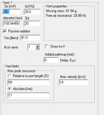
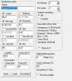
2. Required power vs Vb

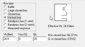
Recalling J. A. Hofman’s “iron law”, I decided to investigate the relationship between an enclosure’s Vb and a power that would satisfy the above-proposed standard. I started with Vb=100l, not due to any sophisticated reasoning, but simply because I had built such an enclosure; the idea having been that I had to start somewhere, and by comparing a model for the specific Vb with a measurement, it may be reasonable to correlate to different volumes.

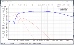
Using Unibox v. 4.08, I had adjusted the power to the required SPL at 40 Hz. I repeated the exercise for different volumes, cf., Table. 2.

Notes: (i) Table 2 summarizes the model without any consideration for a room gain;
(ii) I was not concerned about exceeding the Xmax for the frequencies below the 40 Hz as this is an implementation and not conceptual issue.

Conclusion/Discussion

1. The parameters Fb and even more F3 are not strongly dependent on the change in Vb;
2. There is an inverse relationship between the Vb and the Qts;
3. There is an inverse relationship between the Vb and the power, which agrees with the “iron Law”; and
4. There is no escaping the conclusion that, assuming that the above-defined standard is to be achieved, a power higher than presented in the links is needed.

Provided that the conclusions are correct, and please do not hesitate to point any flaws in my diatribe, the above now presents at least two questions:

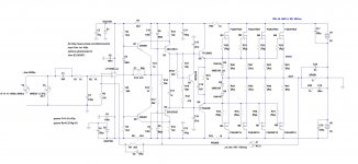
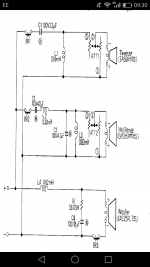
1. What would be the best architecture for an amplifier that will be most of the time supplying power 30 dB below peak, considering preliminary frequency of operation 40 Hz – 350 Hz?; and
2. Disregarding WAF, is there any guidance on selecting the Vb, considering the Vb to Qts relationship?

Kindest regards,

M

Table. 1

Driver Fs [Hz] SPL /1W/1M [dB]
TAD1601A 28 97
TD-15M 34.7 97.8
JBL2226 40 97

Table. 2

Vb [l] Fb {Hz] F3 [Hz] Qts Max SPL [dB] Power [W]
101.7 56.1 60.81 0.655 116.30 155
111.9 54.15 60.81 0.632 116.30 145
122.1 52.47 60.26 0.617 116.10 140
132.3 51.01 61.38 0.601 116.00 135
142.4 49.72 60.81 0.585 116.00 130
152.6 48.57 61.94 0.576 115.60 125
Projects by fanatics, for fanatics
Get answers and advice for everyone wanting to learn the art of audio.
Join the Community
507,758
Members
7,887,127
Messages

Filter

Forum Statistics

Threads
406,169
Messages
7,887,127
Members
507,758
Latest member
Cindy