Hi All,
I read somewhere that these tubes are designed for cascode use and that each triode in the envelope has slightly different parameters, particularly the max allowable Vhk.
However, I have been unable to confirm from this from any datasheets. With the possible exception of a a slight difference in some of the interelectrode capacitances, I can't find any mention of different parameters for each triode.
What, if any is the difference between the two triodes in the envelope?
If different, is it significant enough to preclude the use of the two triodes in one envelope as the input stages for a stereo amplifier?
Many thanks,
Greg
Almost all double triodes have small differences in some of the interelectrode capacitances between the two sections. I would think that these differences hardly matter at audio frequencies, maybe with the exception of the capacitance between the grid and anode (in view of the Miller capacitance). But this capacitance seems to be the same for both sections in the tube types you mentioned (namely 1.4 pF).
The maximum cathode to heater voltage ratings differ between the tube types you mentioned.
For the ECC88 they are 50 V and 150 V when the cathode is positive in respect to the heater:
https://frank.pocnet.net/sheets/030/e/ECC88.pdf
For the 6922 they are 130 V for both sections when the cathode is positive in respect to the heater (but some datasheets state 150 V):
http://frank.yueksel.org/sheets/049/6/6922.pdf
For the E88CC they are 150 V for both sections when the cathode is positive in respect to the heater:
https://frank.pocnet.net/sheets/009/e/E88CC.pdf
My conclusion would be that for audio purposes the two sections are identical (as long as one respects the maximum cathode to heater voltages).
Last edited:
i agree that for audio purposes the two halves are identical. You just have to watch Vhk in cathode follower, phase splitter and SRPP applications where you might sometimes need to use heater elevation. I use the 6922EH in all my designs because it has a Vhk of +-200V which usually means heater elevation is not needed as long as the HT does not exceed 250V.
https://shop.ehx.com/catalog/addimages/6922eh.pdf
Cheers
Ian
https://shop.ehx.com/catalog/addimages/6922eh.pdf
Cheers
Ian
If you search for early 6DJ8 data sheets, you may find the one that mentions the different filament to cathode voltages for triode #1 and triode # 2.
The triode number that has the higher filament to cathode voltage rating is to be used as the top tube in the RF amplifier cascode stage (noted in the same data sheet).
6922, ECC88, and E88CC may or may not be similar to the 6DJ8, even though sometimes they are used interchangeably.
Your Mileage May Vary.
Last edited:
Any of those tubes when used for an amplifier input stage should work well, when wired as a typical single triode gain stage; using self bias, a resistor plate load, or a CCS constant current plate load.
Since it is a dual triode, a single tube works for stereo.
Using the same tubes as an input stage for an amplifier is made much more complex, with more details to pay attention to whenever the input stage is:
an SRPP, Mu Follower, or a cascode stage for a single ended amplifier; Or a cathode coupled phase splitter for a push pull amplifier.
etc.
Just saying.
Last edited:
If you search for early 6DJ8 data sheets, you may find the one that mentions the different filament to cathode voltages for triode #1 and triode # 2.
http://www.r-type.org/pdfs/ecc88.pdf
Cheers
Ian
Thanks for the replies everyone. While we're discussing this tube I will keep going...
Am I kidding myself hoping to use these tubes in a mu follower circuit as shown? It will probably be connected to an EL34 or KT88 running in UL mode. In a stereo amp I would use one 6922/E88CC for the upper devices with an elevated heater supply and one for the lower input devices. Would probably bias to about 5mA or just below the maximum dissipation limit.
I see the JJ 6922 has a max Rhk of 20k - see https://www.jj-electronic.com/en/e88cc-6922-6dj8.
What are the implications for that in a circuit like this? Does it mean I can't use the voltage divider I have proposed since the impedance is so high?
Appreciate any thoughts.
Regards,
Greg
Attachments

I never found a good answer/explanation for this in literature. My main question is: Does the maximum resistance between cathode and heater still has to be respected when there is a large enough capacitor shunting that resistance (which would make the ac-resistance almost zero)?
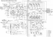
But there are many practical examples where the resistance is much larger than 20K but the resistance is shunted to ground by capacitance. The McIntosh MC3500 is such an example.
Based on examples like this one, I think your plan will work just fine.
Addition: The only thing I'm not sure about is what happens at start-up with a power supply that comes up fast (solid state). The heaters in your circuit than would be at 209 V (or probably even higher) while the cathode still is at 0 V (or maybe better: is still kind of floating). I would feel safer if the power supply has a delay (for instance by using a damper diode in the B+ line).
Attachments
Last edited:
The Philips ECC88 datasheets states which system to use for top or bottom in cascode.
I got it wrong and had to rebuild the nice socket layout I constructed.
I got it wrong and had to rebuild the nice socket layout I constructed.
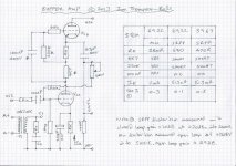
I have used 6922s as mu follower but never at more than about 300V HT. Attached is a schematic of a general purpose buffer board I designed many years ago. You will notice I ran the mu follower option at about 11mA to reduce distortion.
I used elevated heaters but since I was using both halves of the same tube I set it to be about 25% of the HT supply. I used a pot divider like yours with 66K at the top (2 x 33K in series) and 22K at the bottom. All three resistors needed to be rated at 2W.
Cheers
Ian
I used elevated heaters but since I was using both halves of the same tube I set it to be about 25% of the HT supply. I used a pot divider like yours with 66K at the top (2 x 33K in series) and 22K at the bottom. All three resistors needed to be rated at 2W.
Cheers
Ian
Attachments
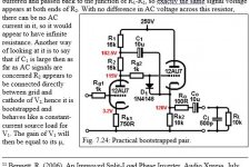
The mu follower is functionally the same as a bootstrapped pair, except the bootstrapped pair doesn't need such high voltages. Hint.Am I kidding myself hoping to use these tubes in a mu follower circuit as shown?

Attachments
Last edited:
Thanks for the replies and insights everyone, I really don't know what I would do without this forum...probably find another hobby.
I look forward to sharing my final design soon.
Merlinb I do like the bootstrap option. I am considering one with a source follower rather than the second tube, it seems to offer some advantages if you don't mind using a solid state device.
I look forward to sharing my final design soon.
Merlinb I do like the bootstrap option. I am considering one with a source follower rather than the second tube, it seems to offer some advantages if you don't mind using a solid state device.
- Home
- Amplifiers
- Tubes / Valves
- Use of the ECC88/6922/E88CC