Earl Geddes - Audio Transducers

I purchased this book from Earl, when he premiered the Gedlee Summas at the Rocky Mountain Audio Fest. Book is in good (not mint) condition. You can read it online for free, but it's nice to have a hardcopy. It's signed by Geddes. Shipping costs me about $15, and I'll sell it for $25 delivered (including shipping.)

If you live in the Las Vegas area, you can have the book if you pick it up.

I just don't want to donate it, as I'd prefer to see someone use the book, not have it wind up in a dumpster somewhere.

Attachments

  • audio-transducers.jpg
    audio-transducers.jpg
    567.4 KB · Views: 55

Can you clarify what WinSD is saying?

I've loaded a speaker driver into WinSL (which I'm completely new to) , the speaker database gave me the WinSL file to use so the numbers are ok .It's the Faital Pro 10FE200 8. 10" bass driver. I've entered "Vented" with a tuning of 30HZ to see the ports and I get results I don't understand. I always assumed that if you used two ports of the same diameter rather than one , they would be around half the length so that the volume of air they contain would remain the same. But I get double the length for two ports of 6.8cm diameter each than for one of 6.8cm diameter. It also offers a Cross Area that is half as big despite the port diameter remaining the same . And some figures are greyed out , is this simply because they are not for varying?
Screen Shot 2025-02-24 at 11.53.37.png
Screen Shot 2025-02-24 at 11.52.45.png

SAE Mark III relay

I recently re-capped my old SAE MK III amplifier and thought I was done with its rehab but discovered another problem. The output-protection relay contacts had become resistive and noisy. Knowing there was little to no chance of finding an exact replacement, I looked at the relay protection circuit in the service manual, and also found an online series of youtube videos describing the repair of a MK III that included replacing the output relay. In that video the original's relay coil was indicated to measure 830 ohms, which is an in-between value for a lot of currently-available 24V relays. Most are much lower, which would be a problem in terms of exceeding the manufacturer's maximum power dissipation specification (900 mW). Why do that if you don't have to? So....

I looked at a number of 24V relays from Omron but they all would require an additional series resistor capable of dissipating several watts. But the coil resistance of their 48V relay P/N LY2-DC48 is high enough @2.6K to use a 1.2K, 1W series resistor, while keeping the PD in the relay coil below the max-limit. The available drive voltage is 75V so THAT is not an issue!

It's about $14USD from DigiKey (2025 prices).

Just putting it out there for someone else now or in the future. The lifespan of industrial electrical components tends to be much longer than consumer-style devices so (hopefully) this info will be useful for some time to come.

BTW I checked the bias voltages that set the idle current in the amp's output stages. After 30+ years they are pretty close to the value given in the service manual. I can't complain about that!

A second BTW: the service manual is incorrect w/regard to the measurement points, at least in the text description...it says they are the collectors of Q13/Q14, which are the driver transistors for the output board. The schematic is correct, indicating that the points are the BASES of those transistors (but the most-convenient measurement points are the collectors of the transistors driving Q13/14 i.e. Q9/Q10). I didn't find any comments on the internet regarding this...but it has to be the case.

Preamp with a huge gain of 350 times.

I am attaching a simple preamp using two NPN transistors. The gain is 350 times and the distortion is just under 0.1%. Since the no signal voltage at the collectors depends on the supply voltage, it is in fact approximately Vcc/2, this preamp requires a very clean power supply that is regulated.

The preamp tries to linearise the base emitter characteristic by using a resistor in parallel with the base-emitter junction. It achieves local negative feedback using a resistor connected between the base and collector. The preamp also uses global negative feedback.

Since the preamp does not self oscillate and is using global negative feedback without a Miller compensating capacitance, it is interesting to investigate why.

Attachments

Need help for SE 300B 5K output transformers

Hi,

This is my first build into the tube world and I'm currently shopping for outputs. I'm building Tom's DG300B SE amplifier and it requires 5K primary and I'd like to get 4 and 8 ohms taps. Tom suggest 15W+ outputs in the manual so that's what I'm aiming for.

Here's what I found so far and I'd appreciate all the feedback about the models/brands if you're experienced with them and I welcome any suggestions as I'm new to tube amp building.

So here's the list I've eyeing

Monolith Magnetics S-11
Hashimoto H-20-7U
SILK (SEC) S-525F
James tranformers JS-6123H (but way overprice on ePay) Unobtanium...

Thanks for your help

Somewhat versatile PLLXO Board (SVPLLXO)

This is my first pcb pretty much. Hoping to get some comments and criticisms. My main question TBD is the hammond case has a pc slot that looks tb 2mm but i dont want to pay for 2mm board right now. Will i get proper bonding between exposed copper and hammond pc slot with 1.6mm thick board?
Gerbers attached
Schematic Attached (PLLXO SCH>PDF)
Not sure how to share kicad project but i would be happy to
A chart at this sight is helpful for choosing values
http://www.troelsgravesen.dk/High-Pass-Filter.htm


Purpose
-Rca to Xlr with filter for SE source to Hypex amp
-First order high pass filters (capacitors in series array using dip sw) x12 position for both pos and neg
-General attenuation I.e. Dac--Resistor in series---amp (resistor in series array using dip sw) x12 position for both pos and neg
-voltage divider (example use case, drop dac output to just use the upper end of dac volume cntrl)
-Resistors to ground array using dip sw x12 position for both pos and neg
-Splitter if you want to to 1 xlr/rca in ---2 xlr/rca out
-Avoid buying vandersteen HPA for a pair of speakers i have

Profile
-I think i made it to slot into Hammond 1455N1601 160mm/103mm
-Height will depend on connectors and caps but the 53mm should work just fine for most everything
TO DO front and rear panel cutout sheet

to save money on build
- use jumper wire instead of dip sw
-only install a few cap/res that you know you need (or clean your floor)
-cardboard enclosure

Resistor package imp0805 metric2012
Cap footprint various from 5mm to 30ish lead spacing

Looking like an all out build with basic caps and res will be approx $200 for a pair Ie Left/Right


PLLXO TOP.jpg

Attachments

  • Like
Reactions: savvas

Antek transformers, question about models AS vs AU

Shopping for a couple of transformers for latest build with and noticed something I had not previously. I wanted either 18 x2 200-300 VA. First I looked at 200 VA, and saw two types, an AS version and an AU version. Pretty sure I had AS versions in past. One type, AU stated only one rubber pad, while AS states two rubber pads.

Further confusion when I looked at 300 VA, only AS version listed, one rubber pad. As already stated, normally have AS version with 300 VA, but what up with only one pad? I must be missing something, plenty of pads around here, but I must be missing something. I have ordered scads of these transformers over the years and never noticed all this! I am missing something and I find nothing on their site explaining. Last build I ordered 18 x 2 250 VA Avel Lindberg from Parts express but the pair from Antek would same 40 bucks on the pair.

Thanks for any schooling here!

Russellc

Cyrus-III restoration project

§ The Motivation:

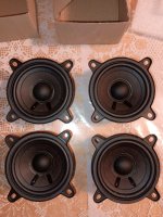
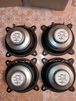
We have a couple of OLS loudspeakers, over 20 years old. OLS is a small company in Breda, still designing and selling loudspeakers, so they must be doing something extremely good. So, more than 20 years ago, together with a friend of mine we build 4 kits ‘OLS Emotion-III loudspeaker together. At that time, named after one of the original designers: Charles van Oosterum, who now owns Kharma, the non-speaker-kit successor of OLS. (Look at Kharma.com for their loudspeaker range) I still love my old OLS beasts, due to the Focal tweeter and Audax low-mid driver. but I found out that I needed amplifier improvement.

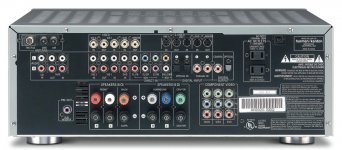
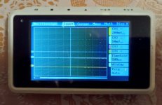
We had a Harman-Kardon amplifier, one of the 5 in 1 beasts, pretty old now, even without dolby. I decided to skip all these option and to turn back to basics: Back to stereo only. The reason is obvious: See attached picture 😕

First I ordered a budgetary Rotel amplifier, with some whistles and bells only to be able to play directly from a streaming server, but the sound was too cold: All the warmth was out and the mid-range sounded undefined. Again, I needed something else…

On DIY Audio I scanned around for amplifier concepts and schematics. Suddenly I clicked this link:

http://www.diyaudio.com/forums/soli...hematics-later-models-wanted.html#post1998327

(Many many thanks, tiefbassuebertr ;-)

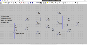
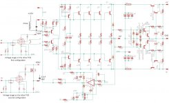
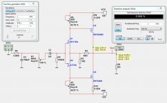
And then I found info about the Cyrus-III amplifier. Immediately I liked the concept of the amplifier stage: It is setup extremely basic and smart: Very good designed differential amplifier/current source, followed by a voltage amplifier, which is collector coupled to a 3 stage current amplifier. A bit conventional maybe -in today’s view- but very very well designed. This design is aged in todays perspective, but it certainly can stand a good test against modern amplifiers. So I decided to look out for a 2nd hand Cyrus-III. After a couple of weeks I found one for EUR 250,- in a reasionable state. Quickly picked it up, paid for it, went home and connected it to my old OLS speakers.

I was stunned.

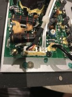
This is what I have missed for a long time: Warm, but extremely well defined in the whole frequency range. You can isolate each tiny instrument individually, clean, smooth, but not confronting you in an aggressive way. Here the golden combination of the Focal dome tweeter and the Cyrus-III really came to praktise: Man, was I satisfied. This is 3 years ago now. After more than 20 years in service I decided to open it up and to improve it with new capacitors. This turned out to be a very wise decision: The capacitors used were 85deg. types regular ones, over 20 years old, so near to death. After doing this I connected it back to my speakers and listened again:

I was even more stunned.

With my music choices, mainly progressive jazz: Charles Mingus, Tony Williams, Allan Holdsworth, Lester Bowie’s Brass Fantasy, from horns to drums, from piano to guitar, what a fantastic amplifier. The definition simply is amazing !

In the time being I had some friends and one customer over to listen to this restored amplifier. Today we already refurbished 9 Cyrus-III 2nd hand amplifiers: 3 in and around our house, and 4 with and for friends, and 1 for one of our customers. Now it is time to share this with you here on this forum of what we have done.

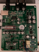
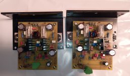
Plan is to do this in a couple of posts, hopefully with photo’s attached to show to you what we have done. The question is: Can *you* do it? Well, if you are able to solder SMD parts you can: It is actually basic stuff, replacing some caps here and there. We did not change the concept of the amplifier by itself, because we find that this stands strong, even today ! 😀

Attachments

  • Harman-Kardon_MiseryAtItsBack.jpg
    Harman-Kardon_MiseryAtItsBack.jpg
    168.6 KB · Views: 813

QUAD 33 preamp balance mechanism 3d model help

hello
i need 3d model of balance mechanism for quad33, or only model of top part and i will glue it on my broken, there is no more 3d model online i check every place, was before year or so on few pages but now its not available online anymore so need help, dont wnat o buy new part this is easy fix so need help if anyone can send me 3d model

480490836_10232721942566928_3287870957561494540_n.jpg

Reproduce the instruments as in the opera

hello,
I would like to reproduce the instruments as if I were at the opera or in a live concert. A few years ago I heard that to achieve this result you needed 16 speakers distributed throughout the room. I find that my experience with a pair of fullrange speakers is already much better than with a multi-way system on this point. In your opinion, how many speakers are needed to achieve this objective?

REL T5

Hi Everyone,

Looking for someone with a REL T5 to check voltages on the connection between the input board and the amp. There is a 4 pin connector going from the Amp to the Input board as pictured. I need to know the voltage of the power supplied to the input board. I assume its the Red and Black cables and the yellow and which are the signal inputs for the amp.

Help is appreciated.

Cheers,

Attachments

  • IMG_2254.JPG
    IMG_2254.JPG
    399.1 KB · Views: 852

Re-purposing concrete speaker cabinets

I acquired a pair of Avance 190 speaker cabinets last the weekend. I believe they date to the 1980s. The cabinets are about 96.5cms (38ins) tall, curved and tapered from bottom to top and with an angled back baffle. I've calculated the internal volume to be about 40 litres (1.4cu ft).

due3VMr.jpeg


The cabinets are made of a concrete material and are in pretty good condition, though all the original drive units are missing or faulty.

I'm hoping to repurpose them with some full-range drive units in a bass reflex configuration and will be glad to hear recommendations for some suitable units. Not too expensive as the plan is to gift the finished speakers to a family member.

Thanks.

For Sale B&O Beogram 1202 & 3000 OM 5 Cartridge Installation Kit

This plug-and-play kit enables you to install an OM 5 cartridge in place of an SP-series cartridge. The kit includes all necessary components, including a specially designed adapter that ensures a secure and proper fit.

Price List:

OM 5S – 185€ + shipping
OM 5E – 195€ + shipping
Super OM 5E – 225€ + shipping

The adapter provides a simple, reliable connection between the OM 5 cartridge and your existing setup, ensuring an efficient and hassle-free installation.

IMG20250124231206.jpg
IMG20250124231211.jpg
IMG20241124112325.jpg

Anyone tried Ustarts Audio BD93 AK4493 DAC board from Aliexpress?

Hi everyone!

I am curious how this board measures and if anyone has done any listening tests?

Seems like a nice project.

There is small input board that can accept Amareno USB, coax, toslink, and has screen wwith buttons.

I might go for it since everything together is $100 and adding PSU and case should be result in around $150 for the whole project.

Still thinking on this though

Attachments

  • IMG_2561.jpeg
    IMG_2561.jpeg
    116.2 KB · Views: 401
  • IMG_2562.jpeg
    IMG_2562.jpeg
    150.1 KB · Views: 410

Decision: Troels' Fusion 22 VS Faital-12-430

Hi everyone,
I am trying to decide between 2 speakers from Troels. To me as a novice who never built a speaker before, they seem very similar and it is common knowledge that the man himself does not answer any speaker choice questions.

The 2 speakers in question are the following two:
http://www.troelsgravesen.dk/FUSION-22.htm
http://www.troelsgravesen.dk/Faital-12-430.htm

Both of them are marketed by Troels as alternatives to the Faital 3WC-12 with deeper bass, and that is exactly what I am looking for.
But then, I have no clue based on what criteria I should make my final choice.
To me as a noob the specs seem very similar. But then I may be missing some critical difference on which I could base my decision maybe?

If it matters:
  • Large living room (50m2)
  • Power Amp: Hegel H390
  • Primary genre: electronic music

Building a Audio Amplifier for Home Audio System

I am planning a DIY electronics project with the goal of designing an amplifier that can drive speakers with high fidelity and power for my home audio system.

I am going to use either the BD246C or TIP42C transistor as the core of the amplifier to provide the amplification needed to drive the speakers to high volumes. These two transistors look similar, does anyone know which one is better?

PCBs and built boards for PCM56 or AD1865

I want to build one or two fairly simple multi-bit DACs with cheap and available legacy chips, which right now looks like PCM56 or AD1865. All the TDA1541 and PCM63 type stuff has got rare and expensive now.

So point me towards some PCBs or built boards that can be used with PCM56 or AS1865. There seem to be quite a few on AliExpress and I'd welcome advice on which are good ones to buy. Input could be SPDIF or a I2S board.

I can build with tubes so could add a tube output stage and I can build power supplies. But useless with SMDs, that's not possible so a built board would be best.

Hopefully this thread could inspire others to build available, cheap and simple DIY multi-bit DACs.

Real World Measurments of the classic Subwoofer-Designs

Hey there,

I am currently learning Akabak and my method for now is to rebuild existing designs in fusion 360 and simulate them with Akabak, then comparing them with real world measurements.

While this worked out pretty good with the HD15 and the Invader-Bin, I would love to find more actionable, reasonable data to compare them with my simulations.

Maby someone here build a speaker with an accessable plan and has some measurments?
Or maby you have a thread in mind in the internet like this one: https://forum.speakerplans.com/hd15-measurements_topic105533.html ?

Cheers,
C

Gain structure - the easiest way to measure ?

Hi all, I am thinking through my Av system which is predominantly old Hi-Fi and wanted to see how the gain structure works for my subs and measure how I increase and decrease gain to possibly structure in a better way.

Say for the Left speaker I go from my BR 4K player to a naim 32.5 which then goes to a mining DSP 10x10 HD (I reduce the gain by 10db to match the LFE channel which is direct into the DSP) and then this all drives 5 subs in a matrix set up)

So for say one sub from the left channel I am Xmv from the BR player which is changed at listening volume to Ymv leaving my pre amp then Zmv leaving my DSP then Tmv leaving my internal preamps in my subwoofer amp then finally Smv leaving my power amp

What is the best way to measure this with REW, the generator and which function ? my subs are only <65Hz

Class D amplifier without output chokes

I found this micro amplifier with TPA3116D2 on Amazon, two boards for about $14.00!

HW-710-2.jpg


Given the size and low cost it could be useful to replace the internal amplifier in an active subwoofer, but I have a couple of questions:
  1. the first thing that catches the eye is that it has no inductors, no LC filter on the output, so I wonder how the modulation signal does not reach the speakers?
  2. To use it as a mono amplifier you have to modify the chip configuration as per the datasheet for the PBTL mode I guess, can't I simply bridge the two channels? (It would be too easy! 😆)
  3. Without a heatsink up to what voltage can it be powered?
Thanks

Markaudio Alpair 12P with Changtse MLTL Cabinet

Hello,

I believe that many MarkAudio 12P Full range driver owners built Super Pensil or Bented Bookshelf Speaker Cabinet.

I am wondering if anyone has tried this Changtse MLTL Cabinet design suggested on MarkAudio 12P Product page? (See attached cabinet design from MarkAudio Website).

It is narrow but very tall and rear vented design. I thought that it looks very interesting and wondering if anyone has experience this kind of cabinet for full range driver.

Thank you and look forward to hear your thoughts.

Attachments

  • Changtse-Alpair-12P-MLTL.png
    Changtse-Alpair-12P-MLTL.png
    100.2 KB · Views: 396

How to debug class G output stage?

I am using this as a single thread for my questions relating to a current driver I am making - I'm trying to design a simple class G output stage for driving current into a coil*, this circuit is used inside a larger circuit. I am trying to use an op-amp to feed the output stage directly as I don't need any signal gain.

Having amended the circuit as per stigigemla's advice I now have a working circuit but I have a couple more problems -
  • The response is much lower bandwidth than I was expecting - the bandwidth of the output devices is listed as 1MHz, but I get roll off around 10KHz - what dictates the roll off of this amplifier and how can I choose transistors to push the roll off up to around 150KHz (if possible?)
  • When testing the real circuit in the flesh there is an oscillation of a couple of hundred mV overlaid on the output. It doesnt seem to be feedback in the global feedback loop, because changing C1 and C2 dont seem to affect it, but when I cut the global feedback it no longer appears. The real circuit does not yet have the 0.22R emitter resistors which I will add in the next few days when they arrive.
  • There is a large spike in the output when the outer transistors turn on, what is causing this?

* I have added amended the circuit pics to reflect the changes I have made and to clean up the confusing power supply labelling *

//Original question//
As far as I can see the circuit looks OK but in simulation the outer transistors never turn on and the output is clipped at the inner voltage rails - could someone help me understand why, and how I rearrange my circuit to give the desired operation?
any help much appreciated!
* I realize that a lot of designs use PWM for this, but I need to use direct current here.

classABtest.png

Attachments

Hello

I am in my 40s and have built my first DIY speaker in high school ...

but my focus lately was more on learning than building ...

when i started i needed good speakers and thought DIY was a good way to save money ...

since then i have decided that i have no interest in building anything that can be purchased commercially and that DIY for me is about expressing myself and not about fighting capitalism ...

if you DIY to fight evil greedy capitalists and their profit margins that is fine, but to me there is nothing evil about businesses making profits and if somebody like JBL, B&W, KEF, Genelec etc. make good speakers they have every right to charge for it whatever they want even if it costs them 1/10th as much to build it.

my goal is to design speakers and subwoofers that for whatever reason the big boys failed to design. the big boys have very specific ideas about who their customer is and what that customer needs and they will never build something for which they feel there is no market. this is my opportunity as a DIYer.

a DIYer doesn't need to worry about having a market for his speaker because he is the market. this gives us freedom the big boys do not have. freedom to express ourselves.

if you disagree you are wrong but that is also your right.

Reducing DC Voltage after Rectification

I am building an stereo amplifier using two separate mono boards. Each board accepts a max voltage of +/-55VDC. I would like to provide +/-50VDC to each board. My problem is that I am using a 40-0-40VAC toroidal transformer that, after it has passed through a rectifier board, produces +/-58.5VDC. I’m hoping there is a way to reduce this down to +/-50V while maintaining a viable ground scheme for the input voltage to each amp board.

The rectifier board has 6 output terminals: 2 – positive, 2 – negative, and 2 ground. Each amp board has a positive, negative and a single ground input for the voltage, which is perfect. I have a couple of buck regulators that nicely reduce the voltage, and I would hope to use one to power the B+ and one to power the B- rail for both boards. That raises some questions:
  1. Can I use 2 buck converters total: 1 BC to power 2 amp modules (i.e. send the +50V out to 2 different B+ rails)?
  2. Do I need 4 buck converters: 2 BCs for each board. Each rail getting its own dedicated BC.
  3. Either way, how would I handle the ground connections from each of the BCs to the amp board? Since there is only one ground input on each amp board, I’m doubting that it is okay to connect the two separate grounds from the 2 BCs to the one GND terminal. In effect, by using the buck converters I no longer have a 50-0-50V sources but rather two 50V sources.
Side-stepping the issue of simplicity, do I need a absolutely need a lower voltage transformer (i.e. 35-0-35)? I have been running the amp from a 30-0-30 transformer, but it only provides 40V to each rail.

Many thanks,

Jonathan

Hello from South East Kansas.

Hello everyone. I'm an ex pacemaker engineering tech who worked for a company that was located about 40 miles straight south of Houston, right on the gulf. I'm 65 and have been interested in audio since hearing my first set of Maggies at Beatty's Stereo in Kansas City around 1980. I am currently refurbing a pair of 3.6R's. This is my fourth set of Maggies. Began with a used set of MG1's, sold them and bought a new set of 1.5's, traded the 1.5's in on a new set of 2.7QR's that I still have. And about a year ago, drove about 4 hours each way down to Dallas and picked up this set of 3.6R's that I'm restoring, and upgrading ALL of the internal crossover components.

I have built a pair of W frame dipole subs a la Sigfried Linkwitz, using four Acoustic Elegance Dipole 12's. Using dsp to set an 8mS delay to the Maggies, this is the best subwoofer match to Maggies I've ever heard. I've bought four of the Dipole 18's to build another set of the subs to high pass around 30 to 32 Hz, thus relieving the 12's of anything below about 32Hz. But I haven't got the cabinets for the 18's built yet. I'm just a working guy, so it took me a long time to save up the money for these expensive drivers.

Meanwhile, during some house remodeling, the midrange of one of my 2.7's quit working. Haven't got a chance to tear into it yet, cause my workspace is completely covered with this tore apart 3.6.

I think I'm going to enjoy being a member of this forum. Looking forward to hearing from you all. Will keep my progress posted for anyone interested.

Ampli PCL82 + 2A3

Hi I have to repair BAD homemade amplifier..
a Chinese board was used, there is a scratch to the up and down of the volume,.. on left and on right obviously the potentiometer are changed, and one of channels has the transistor that don't work fine it has a very low gain.
When I detected it with a tester components, is see it as a resistance, while when measured with the multimeter it corresponds to an NPN transistor but also results in a resistance in the two terminals,
the test with multimeter.... The collector is in the middle..

The audio signal is the yellow wire, and the out of the transistor go to pin 8 of the tube.. on a cathode, then low impedance.

Someone knows something ?? Someone know some reference ? Schematic ?? Transistor kind ?

Thank you for now

Ampli.jpg

IMG_5883.jpg


Login to view embedded media

Greetings from Vancouver, BC, Canada

Hi all from Vancouver, Canada.

I'm mechanical designer by profession and I've worked in some audio equipment projects in the past. I love hifi equipment and spend lot of time listening to different styles of music
Since I was a kid I've been tinkering with electronics watching my dad repairing radios, amplifiers, etc.. and I really enjoy DIY.
I came to this forum with the idea to learn more about speaker design.
Currently would like to find a DIY kit or guide to built similar speaker to the Totem Sttaf, Arro, Hawk, Forest, Spendor A2 and similars.

Thank you for accepting me!
Best,
Henry
  • Like
Reactions: Exlssn

Line Array 1 khz to 10 khz

i want to cross to supertweeter at 7-10 khz, the supertweeter would be a line array of

https://www.parts-express.com/HiVi-RT1C-A-Planar-Isodynamic-Tweeter-297-400?quantity=1

i am not partial to partsexpress by the way. i would buy everything wherever it is cheapest.

i think this driver makes a lot of sense as supertweeter line array ...

i can also use an array of cone drivers below 1 khz ...

it's the 1 khz to 10 khz i can't figure out ...

there is this:

https://www.parts-express.com/GRS-PT6825-8-8-Planar-Mid-Tweeter-8-Ohm-272-126?quantity=1

this:

https://radianaudio.com/collections/ribbon/products/lm8k-wide-band-planar-ribbon-transducer

and this:

https://www.parts-express.com/Peerless-830983-2-Full-Range-Woofer-264-1042?quantity=1

( it's twice as cheap at digikey, but they have a long link )

in case of peerless you would have to use four of the 2" drivers as replacement for every 8" planar. but at $17 each from digikey that's only $70 for four of them or about the same as what GRS planar costs, and 1/3 as much as Radian.

peerless is 82 db / watt and 25 watt

GRS claims 92 db but looks like it's actually 87 db, and claims 35 W

Radian is legitimately 95 db but i am suspicious of 60W because it's so similar to GRS just with bigger magnets basically, which shouldn't have effect on power handling, only efficiency

anyway putting four 2" drivers in parallel should bring overall efficiency from 82 to 88 db and overall power handling from 25W to 100W, which means it now matches GRS efficiency but with 2X power handling and also flatter response and more excursion capability all at the same price ...

the Radian still leads with about 5 db more overall output capability ( even with lower power handling ) versus four Tymphanys ... but is that extra 5db worth 3X the price ?

personally if i'm building a giant $$$ array i want rock concert SPL but it seems that an array of Tymphanys should be able to hit about 115 dba whereas rock concert level is 100 dba ( limited by law ).

does that mean the Radian can't be justified for use in an array system for home use due to its price ?

in a prosound setting that extra 5db could allow the array to throw further but at home this is not an issue.

thoughts ?

Onkyo DX710 Op Amp mods asking advice

Hi guys,

I recently purchased a used Onkyo DX-710 (1993) CD player. It's a decent unit but i think its sound is a bit shrill, strident and steely at times (especially with female vocals) which makes it often unpleasant listening.

I would like to ask for advice whether I could get something better out of this CD player by some Op Amps rolling there...

I opened up the unit and I see a bunch of transistors laying around as well as four (!) NJM4560DX op amps (DIP-8) near the RCA outputs.

However I don't have the technical expertise to decide whether those 4 Op Amps are related to the analog signal processing at all (i guess they are but that's just my guess) or there may be other components doing that, or both.

I thought to upload here the schematics, block diagrams and Printed Circuit Board drawing plus the parts values, maybe someone could identify and advise the best route on this for me.

The 4 NJM4560DX op amps are marked as Q401, Q402, Q403 and Q404 in the service manual.
I also found close to them the capacitors C425, C426 which are 0.1μF and appear to be bypass caps maybe (i found continuity of those caps with pins 4 and 8 of all those 4 Op Amps), maybe there are more ...

If any of those Op Amps worth to replace, I'd wanted to kindly ask whether modern Op Amps would fit the circuit (NJMs have quite low slew rate and frequency compared to newer Op Amp designs as far as I can see..)

I'd appreciate any help, if you need more information from my side I'd be happy to provide it.

Attachments

  • Poll Poll
DIY TDA1541A PCB "D3"

Would you like a through hole version of the D3?

  • Yes

    Votes: 12 52.2%
  • Maybe, depends on the performance

    Votes: 11 47.8%

Hi Guys,

I've started to design a new PCB for the TDA1541A to make space for the 14 decoupling caps that are needed for a 50Hz DEM.

This idea came about from ECdesigns in this post here: 50Hz DEM

This version is based on my previous design, click here to have a read.

Links:

PCB Order Form

Distinction-1541 V3 "D3"
D3 BOM
D3 Schematics
Photo of populated D3 pcb
D3 layer stackup

If you're interested in the I2S to SIM PCB V1 or V2 click here.

Rega Fono Mini A2D - No Sound Output

Hello,

I picked up VinylPlay Record Player which is pretty much Rega Planar 1 + Rega Fono Mini A2D combined Unit. 24v AC power source is powering both motor and this phono board. Somehow motor spins fine but no sound output at all. No hum or hiss but dead silent.

I checked the test voltage points 11v+ and 22v+ and both test point indicate exact voltage. I also measured VOutL and VOutR point and both measured 11v+.

Can anyone guess what might be the issue? I attached photo just took for kind reference.

Any suggestion would be hugely appreciated.

Thank you.

Attachments

  • Vinyl Play.png
    Vinyl Play.png
    5.3 MB · Views: 48

Fosi ZA3 Amp has weird backgroun noise with XLR Connection

Hello.

Has anyone have Fosi ZA3 stereo amp that has background noise when it is connected with XLR Balanced connection?

I recenty got Fosi ZA3 stereo amplifier and it works fine with RCA unbalanced connection but when I connect it with XLR balanced connection, it has weird background noise. It gets louder when volume gets higher. I made quick recording of it. Can anyone tell me what may cause this noise and is there any remedy for it or it is abnormal and need to ask for replacement under warranty?

https://www.dropbox.com/scl/fi/pvfi...1mwmhlvtw5pu427zxl8gp72u&e=1&st=9owpggma&dl=0

Thank you..

WTB TO-270 Acrosound output transformer

Hi all. I am looking for a single Acrosound TO-270 tube output transformer in good shape to pair with one I have. It was designed for 6V6 in pentode (no UL taps), with cathode bias for about 15 watts. The primary is 10k Ohms and secondaries for 4,8 and 16 Ohms.

Please let me know if you have one sitting unused in storage. I would love to buy it. Or if you have one and want to make a pair, make me an offer for mine.

Here are some pics of mine. Colors did not render very faithfully due to lighting I think:

IMG_2340.jpegIMG_2338.jpeg

Thank you kindly.
  • Like
Reactions: OtisCampbell

Is this a bypassed fused cathode of any benefit?

when opening up a 300B SET amplifier I’ve built some years ago I found this “safety circuit”. At the time I thought this was a good idea to protect the tube and the output transformer, if something would go wrong.
Not I’m not so sure..
’ll guess it could cause inductive voltage spikes if blown

Could this fuse cause bigger problems than it protects?

The amplifier is actually a monkeystyle amplifier with 650V at B+, but here simplified to give a better understanding of the concept.

Attachments

  • IMG_7647.jpeg
    IMG_7647.jpeg
    505.4 KB · Views: 87

Mid measurements - nearfield and 1meter - WTH?

Hi.

I'm getting into quasi anechoic measurements of my active floorstanders. There's one thing that I don't understand and I can't really find an answer to.

When I measure the midrange (Revelator 15M) nearfield I see its typical rise of SPL from 1kHz and up, which would somehow correspond to the factory SPL, but as soon as I move the mic away (let's say 1m), the results change pretty much (the response flattens).

I was thinking it may be some baffle diffraction, so I made my first simulation in the Diffraction tool of Virtuix CAD. IIt seems that it could possibly it, but would it really be up to that point? According to graph, the simulated diffraction should have a lesser impact than it really seems to be...

Below you can see the, my "measurement setup", and:
  • nearfield measurement (red plot)
  • 1m measurement ("blue" plot)
  • manufacturer SPL (left)
  • Diffraction simulation from Virtuix CAD with baffle and midrange speaker location specs (bottom)


I'd be grafeul on any thoughts.


1740347119396.png


1740350040089.png

Recently built myself an OTL headphone amplifier using three Svetlana 6N1P tubes

I recently had a lot of fun having a go at building an OTL headphone amplifier using three Svetlana 6N1P tubes I bought online from Evatco, there are a few reasons why I decided to have a go at building one, firstly, I was curious to find out what it would sound like, secondly, my 43 inch Blaupunkt HDTV does not have a headphone out socket, only an optical digital audio out, so I needed some kind of an amplifier, thirdly, I thought that it would make a good and fun diy audio project, so I did some searching for OTL headphone amp schematics and found a really interesting build article on the Headwize Memorial website by a guy named Bruce Bender, the article was based on another very similar OTL headphone amp, the schematic in the article looked easy enough to build, so I started ordering all the needed parts online, once I had all the parts I needed, I got to work on marking out all the hole centers I needed to drill and cut in the diecast aluminium box I used for the chassis, I used some matt white prime and paint to spray paint the chassis after drilling and cutting all the holes, then I used my labelmaker to make adhesive paper labels to stick on the spray painted chassis before using some satin clear coat spray to seal it all.

After doing all the internal electrical wiring, I plugged the amp into my newly bought 500VA Variac, turned the amp on, and slowly turned up the output voltage on the Variac while monitoring the +HT supply with a multimeter, after I had increased the Variac's output voltage to 250V AC, the +HT was measuring +306V DC, and as far as I could tell by doing voltage checks with my multimeter, the amp appeared to be operating normally as it was supposed to, so, I hooked up my new FNIRSI 100MHz Digital Dual Trace Oscilloscope/Function Generator and fed in a 1kHz sine wave signal into each of the amp's stereo line inputs and monitored the outputs with the oscilloscope, I saw a very clean looking 1kHz sine wave signal on each of the amp's outputs, next, I plugged my new pair of Audio Technica ATH-M50X headphones into the amp's headphone out socket and had a listen, I was pleasantly surprised to find that the amp could drive the Audio Technicas plenty loud enough even though the headphone is rated at 38 Ohms impedance, I tried playing some music from my studio pc through the amp, and if my ears aren't lying to me, the sound quality was awesome, really crystal clear with nice bass, mids, and highs, I could clearly hear the subtle nuances in the music, there's none of the "ear fatigue" with this amp that I get when listening to a solid state amp, apparently from what I read in the articles my amp build is based on, the frequency response is ruler-flat from 10Hz to 100kHz with gentle roll-offs, the amp sounds relatively free from any obvious distortion, I read somewhere that the 6N1P tube is regarded as being very linear, there is practically zero hum-noise even when the volume control is turned up fully, it is a very quiet amp due to the tube heaters being powered by a 6.3V DC supply that is deliberately floated above ground via a 220nF/630V film capacitor.

I'll see if I can post some pics of my OTL headphone amp build later on once the admins have approved my thread post.....stay tuned!!!!

XLR and Power connectors, Switchcraft/Hubbell

For sale 20 female right angle Switchcraft connectors. These have been used before, in great condition. They are all missing the rubber boots that are for strain relief.
Sell 10 for $30 shipped in USA, all 20 for $50 shipped USA.
.
Selling 5 Hubbell hospital grade 20 amp plugs, new in boxes. These will not work in a normal 15amp outlet, please look at the picture. They will work in a 20amp outlet.
awesome quality. all 5 for $50 shipped.

Attachments

  • hbl1.jpg
    hbl1.jpg
    555 KB · Views: 59
  • hbl2.jpg
    hbl2.jpg
    409.7 KB · Views: 62
  • swcrft1.jpg
    swcrft1.jpg
    488.2 KB · Views: 64
  • swcrft2.jpg
    swcrft2.jpg
    361 KB · Views: 62
  • swcrft3.jpg
    swcrft3.jpg
    506.9 KB · Views: 59

Reel to reel rubber spool lockers, triad output matching transformers

6 rubber hub lockers for your reel to reel. 4 of one type, 2 of another type. Good condition, original 1960's? all 6 shipped in USA for $20
.
2 big heavy Triad output matching transformers. shipped in USA for $60.
.

Attachments

  • r2r.jpg
    r2r.jpg
    512.5 KB · Views: 63
  • trd1.jpg
    trd1.jpg
    567.6 KB · Views: 65
  • trd2.jpg
    trd2.jpg
    439.6 KB · Views: 70
  • trd3.PNG
    trd3.PNG
    188.6 KB · Views: 70

For Sale GM70 Amps

Due to my age, I am selling my DIY GM70 amplifiers, I just cant move these around anymore and they don.t fit in my audio cabinet.
These weigh in at over 120lbs each.
Hand wired, matching high quality components
Monolith Magnetics 7K OPT
Monolith Magnetics IT transformer, gapped for 40ma
Large Chokes
Spare Edcor power transformers(I had them wound for more current)
Pick up in Florida only
Asking $3000
6E5P PreDriver
JJ2A3 Driver
GM70 output
Class A to 25W, A2 to about 50W.
Rod Coleman supply for GM70
Arduino for startup using 4 relays (90sec warmup)
Ground lift using diode bridge
Simpson amp meters for GM70
Multiple Fuse protection for OPT and amp
A

Attachments

  • Chassis.jpg
    Chassis.jpg
    106.1 KB · Views: 629
  • GM70.jpg
    GM70.jpg
    312.6 KB · Views: 618
  • 1.jpg
    1.jpg
    502.4 KB · Views: 619

DAC "click" sound when playback starts/stops

I've been playing with PCM2900's for a long time, improving my skills of PCB design. A stubborn issue is how I often have a clicking sound on my headphones, whenever playback starts or stops. When I set the volume to zero in a media player, and start or stop playback, the click is distinctive. A few boards didn't have the issue, but I can't reproduce when it does or doesn't happen.

The PCB is double-sided with a good layout, almost all SMD parts, good quality capacitors with capacities according to the PCM2900 datasheet. There's an opamp to amplify the signal, with a switchmode supply. There's an USB common mode filter on the 5v and GND, and an IC to limit inrush current.

I had a look with a digital oscilloscope at the current board. With one channel playing a sine wave and the other audio channel muted. The clicking sound seems to be a bump in the DAC output, right around when the databus starts running.

Power supplies look clean, except for VCOM and VBUS that are a bit irregular a bit before playback starts, that's when the USB databus starts running. There's a big capacitor where USB power enters the board, then a 2R2 resistor, and a 1uf capacitor close to the board. VCOM has a 10uf and 100nf capacitor. All of these are according to the datasheet. Most power supply decoupling capacitors are specced at 1uf in the datasheet, it says 'max 2uf'.

I might go and increase capacitors, I don't know. I'm looking for some help.

bump.png


zooming in on the bump:

bump_zoom.png


Vbus:

vbus.png


Vcom:

vcom.png

For Sale Spring Sales

Hi,
it's time to reduce my gear and get organized.
I ship from Italy and can offer cheap shipping to many EU countries.
4 x Faital 3FE22 16ohm only tested 60euro
https://www.axiomedia.it/it/full-ra...FE69vmZFv88CewBgE6pjkCqo0nJ_4mflNiQFGRtcmUWQF
2x BMR46 XEL new 30euro
https://www.cotswoldsound.com/specifications/CSS_Specification_Sheet_BMR46XEL_N8R_r2.pdf
2x TB W2-800SL only tested 20euro
https://www.axiomedia.it/en/full-ra...u4YN8nzc4e_H2K3hvfazXVGLYuWFEUjshZN-T36ur6ewK
Woofer tester 2 for measure T\S parameters 60euro
https://www.ht-audio.com/pages/Products.html#WT2
Terrasonde The toolbox is a stand alone measurement system that includes a very precise sound level meter, spectrum analyzer generator and much more complete with power supply. 60 euro
Like this: https://www.ebay.co.uk/itm/235007647380
DSO QUAD mini oscilloscope Open source 70euro with probes and BNC adapters
https://www.robo-dyne.com/prodotto/dso-quad-pocket-digital-oscilloscope-black/?lang=it

In the next few days I will include more stuff like DAC AD1862. PCM1704, electrostatic cells, irons, pcb and more.
Thanks and have a nice evening.
Guglielmo

Attachments

  • BMR1.jpg
    BMR1.jpg
    249.5 KB · Views: 49
  • BMR2.jpg
    BMR2.jpg
    233.9 KB · Views: 52
  • DSO QUad1.jpg
    DSO QUad1.jpg
    698 KB · Views: 54
  • DSO QUad2jpg.jpg
    DSO QUad2jpg.jpg
    309 KB · Views: 50
  • faital1.jpg
    faital1.jpg
    561.9 KB · Views: 50
  • faital2.jpg
    faital2.jpg
    727 KB · Views: 53
  • Terrasonde1.jpg
    Terrasonde1.jpg
    474.1 KB · Views: 53
  • Terrasonde2.jpg
    Terrasonde2.jpg
    239.8 KB · Views: 49
  • Terrasonde3.jpg
    Terrasonde3.jpg
    286.3 KB · Views: 44
  • W2-800SL 1.jpg
    W2-800SL 1.jpg
    338.4 KB · Views: 43
  • W2-800SL 2.jpg
    W2-800SL 2.jpg
    448.7 KB · Views: 47
  • Woofer tester2.jpg
    Woofer tester2.jpg
    393.6 KB · Views: 46
  • Like
Reactions: geoturbo

Hiya from a semi retirement

Hi all, I started my hi- fi journey in 1969 with an early Garrard deck and home built tube amp buying 2-3 vinyls every week which I still have. Ended up with Thorens TD160, SME series II Improved arm which got put into storage when kids came along, nearly 40 years ago. Now in semi retirement I’m re-entering the vinyl hi-fi world and with the Thorens/SME now have a NAD 3140 and some Monitor Audio Bronze BX2 speakers. Last job is to get all the vinyls down from the attic. Interested in what is now happening outside of the streaming world !

For Sale Ian Canada UcConditioner Pro 3.3V - the latest 450F, only 3h of use

Selling 3.3V Ultracapacitors pack from Ian Canada

-20% off Audiophonics pricing (145 EUR - 20% = 116 EUR).

UcConditioner Pro 3.3V - the very latest model with 450F caps, only 3h of use. Bought from Audiophonics on 2024-12-28 (invoice provided).

They are currently backordered @ Audiophonics.

Selling due to going BIG on the 3.3V rail - changing to 3000F caps.

Payment by bank wire or PayPal.

Shipping via UPS/DPD 15-20 EUR to most destinations in EU.

1740343340732.jpeg

A question about the basics of PS filtering

Looking at supply for tube heaters and noodling around with possibilities in PSud , I hit something I've seen many times but never really understood.

Shown here first sim is with a load calculated as 3.1A@12V =3.87Ω

What I don't get is that while the ripple across the load centres at roughly 20V, the second sim with 0.1Ω resistance in the added filter nets a Vout so much lower.

3.1A through .1Ω is only 0.31V, why does the following capacitor pull it so much farther down?

Thanks

Attachments

  • LC filter.png
    LC filter.png
    89.6 KB · Views: 74
  • LC add RC.png
    LC add RC.png
    96.7 KB · Views: 65

High Power Hybrid Amplifier

I would like to share with you the result of my new hybrid amplifier.

The my first version of this my amplifier was made in 2010 then i made some improvements.

The new version uses a very simple and cheap tube driver with 6Z51P or D3a that can deliver 40Vrms with a single tube.

The distortion is about 1.5% at 33Vrms so about 150W on 8ohm.

This project collects all the experiences made in these years then it born with all these characteristics:
  • no global feedback design
  • passive components without any compromise on any section
  • only few parts on the signal path, only 3/4 active components
  • very short signal path
  • very low output impedance (near to 0.1ohm) for high damping factor (near to 80)
  • very high output current, output devices able to manage 60A
  • high output power to drive any loudspeakers including ESL, 140W on 8ohm and ?W on 4ohm
  • very good slew-rate
  • large frequency band, near to 1.5MHz for the IRF820 configuration
  • high separation from power supply for all the sections
  • power supply separated for each channel
  • zero noise
  • ultra low distortion in the current amplifier
  • zero dc offset, dc servo loop
  • no fuse on the signal path
  • no relay on the output signal
  • only a single vacuum tube for the voltage amplifier
  • only one interstage capacitor on the signal path
  • high input impedance 110Kohm
  • high voltage gain able to be driven directly by any source
  • voltage stage and driver stage working in pure class A operation
  • high efficiency near to class AB
  • compact chassie
The current amplifier is a perfect Diamond Buffer used in some chip like the LH0002 and the BUF634.

This configuration has been analyzed very well in the article Bulding better buffer on Electronics World november 1992.

The same design as been used in many Audio Research amplifiers like the Audio Reasearch D100 and the D400.

Also the Pioneer A-09 and the M-6 use a Diamond Buffer on output stage but these implement dynamic current generators with some stability problems.

Advantages of this type of configuration compared to a conventional:

● compensation of Vbe non-linearities between driver and final so very low distortion without feedback
● high slew-rate and large frequency band
● temperature run-away compensation without sensors if driver and final transistors share the same heatsink
● high input impedance if driver stage use current generator (I1 & I2) auto protected by short circuit on output

Disadvantages of this type of configuration compared to a conventional:

● the bias current in the driver limits the current supplied to the load

It is evident that there are many benefits, but to overcome the problem of the current supplied to the load you need to study well the working points of the driver and final.

All the pcb will be available at low cost on Ebay shop or you can download the Eagle files to produce these in your local area

I don't get money from this Ebay shop.

Attachments

  • Sch2022b.gif
    Sch2022b.gif
    20.5 KB · Views: 1,742
  • Ibridone_2022_thd1_8ohm.jpg
    Ibridone_2022_thd1_8ohm.jpg
    51.4 KB · Views: 1,571
  • Ibridone_2022_freq_8ohm.jpg
    Ibridone_2022_freq_8ohm.jpg
    70.4 KB · Views: 2,040
  • Ibridone2022_sch.jpg
    Ibridone2022_sch.jpg
    160.5 KB · Views: 2,347
  • driver_sch2022.jpg
    driver_sch2022.jpg
    82 KB · Views: 2,348
  • driver_sch2022a.jpg
    driver_sch2022a.jpg
    39.7 KB · Views: 1,797
  • Ibridone_2022_ph2.jpg
    Ibridone_2022_ph2.jpg
    164.6 KB · Views: 1,503
  • Ibridone_2022_ph3.jpg
    Ibridone_2022_ph3.jpg
    160.2 KB · Views: 1,718

hello world

Hello world,
I'm an electrical engineering student from Québec who first got interested in DIY audio equipment at age 14 when I built my first electric guitar. I've got a bunch of projects planned out for when I finish my degree and have more free time/money. I ordered a bunch of old soviet tubes and germanium transistors recently, so hopefully this community will be the right place to get advice on how to not burn them all out 😛
-Mielaumiel

Transformer evaluation, what is acceptable to you?

Transformers, usually toroids nowadays, new and legacy has always been built around some spec. Also EI and other did. Back in the days they had more margins, that’s a feeling I have.

The perfectly normal thing in commercial production is to reach the specs to an as low production cost as possible. To sell more of course.

That probably means that the manufacturer does not make one extra turn on the primary if it holds the specs nominal.

Many trafos, new and older, vibrate, makes sounds, gets warm, barely holds output specs etc. Even without load.

A winder that doesn’t have the economic pressure adds enough winds, enough iron etc to make the product live an easy life for what it’s ment for.

What is your criteria when you evaluate a transformer for it’s purpose? How many degrees over nominal under load. Can it make sounds audible a meter away etc?

Not a purely scientific thread, just interested in your thoughts. Going over a lot of iron in my stash and pondering over what to ditch and what to keep.

Possible to use AI to summarize threads?

I'm interested in building things. There are a lot of interesting things to build on this forum. Sometimes wading through a 100 and however many page thread gets tedious. This lead me to a... wouldn't it be nice if Copilot could summarize some of these really long threads to see if this is something I want to pursue? Alas I tested this and it cannot. Is there a way to do this? If not, maybe there is a path forward to build it into the platform?

Cored inductors for active xovers

Looking to build some basic analog active crossovers to biamp large 4 way speakers.

I'm going from a fully balanced input to the floating individual single ended filters, then back to fully balanced, using input and output transformers.

My concerns are how the inductors will behave in terms of distortion depending on which core materials I decide to use. I want to use air cores wherever possible, but the lower frequency filters will almost certainly require cored inductors.

Anyone been down a similar road with their builds? Any input is appreciated.

  • Poll Poll
Tweeter selection: Ciare HT263 vs Audax TW025A0

Audax TW025A0 or Ciare HT263 for the mentioned below design?

  • Audax TW025A0

    Votes: 1 100.0%
  • Ciare HT263

    Votes: 0 0.0%

Want to build 2-way medium sized BR speaker with waveguided tweeter. Waveguide will be custom 3D printed and tweeter will be mounted from the back. For this I need a tweeter with completely flat faceplate AND it has to be reasonably priced AND available from THLP (I have little better prices from them). Woofer will be 6.5 inch (closer to 6 than to 7).
SICA 6,5 H 1,5 CP 8Ω
https://sica.it/wp-content/uploads/2021/02/Z004100.pdf
BR box of 15-20L size if that matters, manufacturer recommends ~18 Liters 50Hz tuning, so will stick to smth similar. That woofer according to different data is 88-89dB efficient, so both tweeters will have enough sensitivity. Woofer is already chosen, it is underway from e-shop. I will have pretty deep waveguide to align acoustic centers, so there should be enough sensitivity for 2-5kHz region. For design process I will do full measurements and full simulation with VituixCAD, not sure about the exact crossover, but more or less classic 2nd order for woofer and 2nd-3rd order for tweeter at 2000-2800Hz should work. Nothing extraordinary. That is too early to decide now.

The only two reasonably priced tweeters that suit my needs are:

Ciare HT263
https://www.dibirama.it/home-page/tweeter/646-ciare-ht263-tweeter-1-8-ohm-200-wmax.html

Audax TW025A0
https://www.dibirama.it/home-page/tweeter/211-audax-tw025a0-tweeter-1-8-ohm-110-wmax.html
https://hificompass.com/en/speakers/measurements/audax/audax-tw025a0

Both ~25mm, fabric, both have similar SPL curves, both are priced similar, I do not need extra power of Ciare. Dibirama shows kinda better waterfall of Audax, but the same Audax tweeter on Hificompass does not look good at all. Ciare is a little bit more efficient, which I don't know if is advantage with this design.

Another "bonus" tweeter is Ciare HT261, which looks like inferior brother of HT263.

So, Audax TW025A0 or Ciare HT263 ?

External Clock with DIR1703 - HELP

Hi guys, I need some help here.

First of all, let me tell you I'm no techie. Just an enthusiast for music, sound and electronics with no deep knowledge.

I bought a XO2.2 module from Tentlabs to replace the 11.2896 crystal that sets the clock for the digital section on my Plinius CD-101 CD player.
The digital section of my CD player has a Burr Brown DIR1703 digital audio interface.
  • Followed the provided instructions from Guido from Tentalabs, installed the module and no audible difference.
  • Then I decided to measure the clock frequency on the digital section.
  • On the input XTi pin 8 of DIR1703 I have 11.289.583hz coming in from the XO clock module.
  • But on the output pin 4 of DIR1703 - SCKO - that sends the clock frequency to DF1706, etc all the way to the DAC chips - I get a deviation. I measure 11.297.397hz ( a 7.814hz difference !!!) all the way up to the DACs.
  • What I observed is that when the CD is NOT playing ( just idle) I get an accurate clock reading - 11.289.583hz - on the whole digital section up to the DAC chips. This means the input clock frequency is equal to the output clock frequency on DIR1703.
  • When the CD starts playing the clock frequency that comes out of pin4 of DIR1703 changes up to 11.297.397hz . And this clock frequency goes all the way up to the DAC chips.
  • If I hit the STOP button, frequency moves back to 11.289.583hz on the whole circuit.
  • I read the datasheet for the DIR1703.
    https://pdf.dzsc.com/DIR/DIR1703.pdf
    I believe the answer is there but it's too much tech language for me. For what I understand maybe the DIR1703 is set/configured to work with a crystal and maybe a workaround on the CKSEL can be the key? In my case pins 27 (UNLOCK)and 28 (CKSEL) are shorted. If lift one of the pins will I get the correct frequency?
I found a few other threads about the DIR1706 but found no similar problem or answer for this.

Basically I want the 11.2896.387 from the external clock to go all the way in the circuit.
Thank you all!

Andre
Projects by fanatics, for fanatics
Get answers and advice for everyone wanting to learn the art of audio.
Join the Community
507,685
Members
7,884,222
Messages

Filter

Forum Statistics

Threads
406,035
Messages
7,884,222
Members
507,685
Latest member
EvenLouder