§ The Motivation:
We have a couple of OLS loudspeakers, over 20 years old. OLS is a small company in Breda, still designing and selling loudspeakers, so they must be doing something extremely good. So, more than 20 years ago, together with a friend of mine we build 4 kits ‘OLS Emotion-III loudspeaker together. At that time, named after one of the original designers: Charles van Oosterum, who now owns Kharma, the non-speaker-kit successor of OLS. (Look at Kharma.com for their loudspeaker range) I still love my old OLS beasts, due to the Focal tweeter and Audax low-mid driver. but I found out that I needed amplifier improvement.
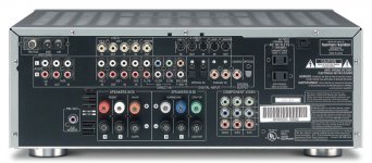
We had a Harman-Kardon amplifier, one of the 5 in 1 beasts, pretty old now, even without dolby. I decided to skip all these option and to turn back to basics: Back to stereo only. The reason is obvious: See attached picture
First I ordered a budgetary Rotel amplifier, with some whistles and bells only to be able to play directly from a streaming server, but the sound was too cold: All the warmth was out and the mid-range sounded undefined. Again, I needed something else…
On DIY Audio I scanned around for amplifier concepts and schematics. Suddenly I clicked this link:
http://www.diyaudio.com/forums/soli...hematics-later-models-wanted.html#post1998327
(Many many thanks, tiefbassuebertr ;-)
And then I found info about the Cyrus-III amplifier. Immediately I liked the concept of the amplifier stage: It is setup extremely basic and smart: Very good designed differential amplifier/current source, followed by a voltage amplifier, which is collector coupled to a 3 stage current amplifier. A bit conventional maybe -in today’s view- but very very well designed. This design is aged in todays perspective, but it certainly can stand a good test against modern amplifiers. So I decided to look out for a 2nd hand Cyrus-III. After a couple of weeks I found one for EUR 250,- in a reasionable state. Quickly picked it up, paid for it, went home and connected it to my old OLS speakers.
I was stunned.
This is what I have missed for a long time: Warm, but extremely well defined in the whole frequency range. You can isolate each tiny instrument individually, clean, smooth, but not confronting you in an aggressive way. Here the golden combination of the Focal dome tweeter and the Cyrus-III really came to praktise: Man, was I satisfied. This is 3 years ago now. After more than 20 years in service I decided to open it up and to improve it with new capacitors. This turned out to be a very wise decision: The capacitors used were 85deg. types regular ones, over 20 years old, so near to death. After doing this I connected it back to my speakers and listened again:
I was even more stunned.
With my music choices, mainly progressive jazz: Charles Mingus, Tony Williams, Allan Holdsworth, Lester Bowie’s Brass Fantasy, from horns to drums, from piano to guitar, what a fantastic amplifier. The definition simply is amazing !
In the time being I had some friends and one customer over to listen to this restored amplifier. Today we already refurbished 9 Cyrus-III 2nd hand amplifiers: 3 in and around our house, and 4 with and for friends, and 1 for one of our customers. Now it is time to share this with you here on this forum of what we have done.
Plan is to do this in a couple of posts, hopefully with photo’s attached to show to you what we have done. The question is: Can *you* do it? Well, if you are able to solder SMD parts you can: It is actually basic stuff, replacing some caps here and there. We did not change the concept of the amplifier by itself, because we find that this stands strong, even today !
We have a couple of OLS loudspeakers, over 20 years old. OLS is a small company in Breda, still designing and selling loudspeakers, so they must be doing something extremely good. So, more than 20 years ago, together with a friend of mine we build 4 kits ‘OLS Emotion-III loudspeaker together. At that time, named after one of the original designers: Charles van Oosterum, who now owns Kharma, the non-speaker-kit successor of OLS. (Look at Kharma.com for their loudspeaker range) I still love my old OLS beasts, due to the Focal tweeter and Audax low-mid driver. but I found out that I needed amplifier improvement.
We had a Harman-Kardon amplifier, one of the 5 in 1 beasts, pretty old now, even without dolby. I decided to skip all these option and to turn back to basics: Back to stereo only. The reason is obvious: See attached picture
First I ordered a budgetary Rotel amplifier, with some whistles and bells only to be able to play directly from a streaming server, but the sound was too cold: All the warmth was out and the mid-range sounded undefined. Again, I needed something else…
On DIY Audio I scanned around for amplifier concepts and schematics. Suddenly I clicked this link:
http://www.diyaudio.com/forums/soli...hematics-later-models-wanted.html#post1998327
(Many many thanks, tiefbassuebertr ;-)
And then I found info about the Cyrus-III amplifier. Immediately I liked the concept of the amplifier stage: It is setup extremely basic and smart: Very good designed differential amplifier/current source, followed by a voltage amplifier, which is collector coupled to a 3 stage current amplifier. A bit conventional maybe -in today’s view- but very very well designed. This design is aged in todays perspective, but it certainly can stand a good test against modern amplifiers. So I decided to look out for a 2nd hand Cyrus-III. After a couple of weeks I found one for EUR 250,- in a reasionable state. Quickly picked it up, paid for it, went home and connected it to my old OLS speakers.
I was stunned.
This is what I have missed for a long time: Warm, but extremely well defined in the whole frequency range. You can isolate each tiny instrument individually, clean, smooth, but not confronting you in an aggressive way. Here the golden combination of the Focal dome tweeter and the Cyrus-III really came to praktise: Man, was I satisfied. This is 3 years ago now. After more than 20 years in service I decided to open it up and to improve it with new capacitors. This turned out to be a very wise decision: The capacitors used were 85deg. types regular ones, over 20 years old, so near to death. After doing this I connected it back to my speakers and listened again:
I was even more stunned.
With my music choices, mainly progressive jazz: Charles Mingus, Tony Williams, Allan Holdsworth, Lester Bowie’s Brass Fantasy, from horns to drums, from piano to guitar, what a fantastic amplifier. The definition simply is amazing !
In the time being I had some friends and one customer over to listen to this restored amplifier. Today we already refurbished 9 Cyrus-III 2nd hand amplifiers: 3 in and around our house, and 4 with and for friends, and 1 for one of our customers. Now it is time to share this with you here on this forum of what we have done.
Plan is to do this in a couple of posts, hopefully with photo’s attached to show to you what we have done. The question is: Can *you* do it? Well, if you are able to solder SMD parts you can: It is actually basic stuff, replacing some caps here and there. We did not change the concept of the amplifier by itself, because we find that this stands strong, even today !
Attachments
Cyrus-III restauration project, the Input Board
§ RIAA Phono Amp, Input Selector & BoardVolume control
As soon as you unscrew the bottom plate of your Cyrus-III, you will see the main board at the bottom, and on top the RIAA Phono Amp, Input Selector & BoardVolume control board, solder side up. This board is called the Input Board (IB).
Unscrew the two screws of which the metal back plate is mounted to the aluminium frame. At the connector side: Unscrew the most left and most right screw in the middle of the top and bottom RCA sockets. Now you are able to move out the backplate with the IB carefully: Bend it away from the aluminium frame carefully. Now remove the white FLEX from the amplifier board and the IB. Note the contact side of the flex, and then clean it and store it carefully. (Contacts are on the RCA side)
You may want to dismount the IB from the bracket as a whole now: Desolder the shielding plate and remove it. Unsolder the green Grounding Wire. Unscrew all 3 screws that are at the RCA sockets side and your IB is available for a fix-up.
First thing you see is a bunch of electrolytic capacitors: They must all be replaced or vanished away from this design. Three main things can be improved here: The +/- 5V regulator voltage ripple and the +/- 15V electrolytic capacitors for all opamp circuitry. The other items to replace are the audio coupling capacitors. Replacing opamps is not useful: The “5532”{*} is a hell of a good opamp for audio. The only reason you might want to replace is the one used for the pickup stage if you have a high-impedance cardridge of more than 22kOhm. If not, the 5532 is very good, even today. Oh, and take care: The phono 1st stage is a single version of the 5532, the 5534. We leave all 1u tantalum decoupling capacitors: They are fine for this task.
First thing to do is to replace C225 and C226 in the phono amp. Originally these are tantalum capacitors, but hey, where is the DC which is needed to keep these caps alive? There is no DC at the output of the 1st opamp stage, and none to fix this at the bias side of the 2nd stage: You might already find a shorted capacitor (not that it cares much here…). Capacitors we used are 2u2/100V X7R SMD for C225 and C226. These are shaped as 1210, so they are pretty big SMD’s. After removal of C225 and C226 you are now able to solder these caps over the old holes immediately: Quick and good.
The output of the phono amplifier also has a couple of unbiased tantalums: C213 and C214: Remove these and solder 1u/100V X7R capacitors. These are shape 1206, and are also suited to directly solder over the old pads.
There are two power supply filter capacitors, specially placed for the phono amp opamps. These are C223 and C224: In our stock we had some OSCON capacitors, 100u/20V. These are *the best* for this purpose. Another option is to use available stuff, like 100u/25V low ESR electrolytic capacitors. A brand that we use a lot in our professional gear is Panasonic. The FC-series is very good for decoupling purposes. Desolder the two old caps, and replace them by the Panasonic FC capacitors, 100u/35V. Take care about their polarity, and do not place them too high on their legs: You might get into trouble building it all together again at a later stage ! (In a couple of our boards we found out that the old capacitors were only 16V, while 15V comes in via the two resistors R231 and R232… That is critical design and probably the capacitors are degraded to 100nF the past 20+ years in stead of their original 100u. Anyway, now you have fixed this problem.)
Looking at the input selector part of the IB, we can identify 2 options for improvement: The coupling capacitors C105 and C106 for the line-out opamp outputs are polarized, while there is no DC level there, and C125 and C126 are candidates for replacement due of their age. Let us start with C105 and C106 first. Remove these capacitors. To replace the old cap we used 47u/16V X5R ceramic capacitors. Shape is 1210. Solder one each over the old pads. This is a bit tricky, but the shape 1210 of this capacitor helps us out: It is large enough to be able to solder it easy.
Depending on the board version you now might expect voltage regulators (7805 and 7905) or transistors for creating the +5V and -5V needed for the multiplexer chips for volume control and for the input selection logic. General rule of thumb is to replace the electrolytic caps for the input and output of these regulators / transistors. We used 100u/20V OSCON for the input capacitors, identified as C125 and C126. Another good solution is the regular FC-capacitor of Panasonic again, the 100u/35V types. Do replace C123 and C124 capacitors too, at the output of the regulators / transistors: 47u/35V will perfectly do here. Mind about their polarity, and mounting height.
The volume control part has a lot of multiplexers (74HC4051) that all run on our already improved +5V and -5V. But around them there are a couple of opamps, and coupling capacitors. C405 and C406 are unbiased electrolytic capacitors again: Remove those two old caps and replace them by 47u/16V 1210 SMD’s. For the opamp low frequency noise filtering, use 100u/35V FC-caps: Replace C419 and C420. Again and again, always watch their polarities carefully. The final electrolytic capacitor we can identify is C424. This is not a critical capacitor, but it is best to replace it with an SMD 10u/25V X7R 1206 capacitor. This capacitor is used to slowly enable the volume control while power ramps up, and to quickly disable volume as soon as power is gone. So it is better to fix this anyway.
Herewith the IB is fixed. What we have used so far for the IB is:
* 2x 1u/100V X7R 1206 Murata Digikey 490-3909-1-ND {#)
* 2x 2u2/100V X7R 1210 Murata Digikey 490-6545-1-ND
* 6x 100u/35V Panasonic low ESR capacitor Digikey P10294-ND
* 2x 47u/35V Panasonic low ESR capacitor Digikey P11232-ND
* 4x 47u/16V SMD 1210 X5R Yageo Digikey 311-2054-1-ND
* 1x 10u/25V SMD 1206 X7R Murata Digikey 490-6519-1-ND
{*} this dual OpAmp is also known as the NE5532, MC5532, BA15532, etc.
{#} www.digikey.com
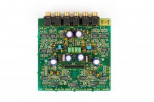
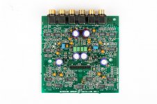
The photo’s show you the very first IB’s we had modified. It has double capacitors for the 47u positions, since I used 2x 22u SMD. But it is better to stick to the above list: Photos are only for illustration. Note that both IB versions are shown in the photo’s, with a high-enough resolution to be able to locate the positions for modification.
§ RIAA Phono Amp, Input Selector & BoardVolume control
As soon as you unscrew the bottom plate of your Cyrus-III, you will see the main board at the bottom, and on top the RIAA Phono Amp, Input Selector & BoardVolume control board, solder side up. This board is called the Input Board (IB).
Unscrew the two screws of which the metal back plate is mounted to the aluminium frame. At the connector side: Unscrew the most left and most right screw in the middle of the top and bottom RCA sockets. Now you are able to move out the backplate with the IB carefully: Bend it away from the aluminium frame carefully. Now remove the white FLEX from the amplifier board and the IB. Note the contact side of the flex, and then clean it and store it carefully. (Contacts are on the RCA side)
You may want to dismount the IB from the bracket as a whole now: Desolder the shielding plate and remove it. Unsolder the green Grounding Wire. Unscrew all 3 screws that are at the RCA sockets side and your IB is available for a fix-up.
First thing you see is a bunch of electrolytic capacitors: They must all be replaced or vanished away from this design. Three main things can be improved here: The +/- 5V regulator voltage ripple and the +/- 15V electrolytic capacitors for all opamp circuitry. The other items to replace are the audio coupling capacitors. Replacing opamps is not useful: The “5532”{*} is a hell of a good opamp for audio. The only reason you might want to replace is the one used for the pickup stage if you have a high-impedance cardridge of more than 22kOhm. If not, the 5532 is very good, even today. Oh, and take care: The phono 1st stage is a single version of the 5532, the 5534. We leave all 1u tantalum decoupling capacitors: They are fine for this task.
First thing to do is to replace C225 and C226 in the phono amp. Originally these are tantalum capacitors, but hey, where is the DC which is needed to keep these caps alive? There is no DC at the output of the 1st opamp stage, and none to fix this at the bias side of the 2nd stage: You might already find a shorted capacitor (not that it cares much here…). Capacitors we used are 2u2/100V X7R SMD for C225 and C226. These are shaped as 1210, so they are pretty big SMD’s. After removal of C225 and C226 you are now able to solder these caps over the old holes immediately: Quick and good.
The output of the phono amplifier also has a couple of unbiased tantalums: C213 and C214: Remove these and solder 1u/100V X7R capacitors. These are shape 1206, and are also suited to directly solder over the old pads.
There are two power supply filter capacitors, specially placed for the phono amp opamps. These are C223 and C224: In our stock we had some OSCON capacitors, 100u/20V. These are *the best* for this purpose. Another option is to use available stuff, like 100u/25V low ESR electrolytic capacitors. A brand that we use a lot in our professional gear is Panasonic. The FC-series is very good for decoupling purposes. Desolder the two old caps, and replace them by the Panasonic FC capacitors, 100u/35V. Take care about their polarity, and do not place them too high on their legs: You might get into trouble building it all together again at a later stage ! (In a couple of our boards we found out that the old capacitors were only 16V, while 15V comes in via the two resistors R231 and R232… That is critical design and probably the capacitors are degraded to 100nF the past 20+ years in stead of their original 100u. Anyway, now you have fixed this problem.)
Looking at the input selector part of the IB, we can identify 2 options for improvement: The coupling capacitors C105 and C106 for the line-out opamp outputs are polarized, while there is no DC level there, and C125 and C126 are candidates for replacement due of their age. Let us start with C105 and C106 first. Remove these capacitors. To replace the old cap we used 47u/16V X5R ceramic capacitors. Shape is 1210. Solder one each over the old pads. This is a bit tricky, but the shape 1210 of this capacitor helps us out: It is large enough to be able to solder it easy.
Depending on the board version you now might expect voltage regulators (7805 and 7905) or transistors for creating the +5V and -5V needed for the multiplexer chips for volume control and for the input selection logic. General rule of thumb is to replace the electrolytic caps for the input and output of these regulators / transistors. We used 100u/20V OSCON for the input capacitors, identified as C125 and C126. Another good solution is the regular FC-capacitor of Panasonic again, the 100u/35V types. Do replace C123 and C124 capacitors too, at the output of the regulators / transistors: 47u/35V will perfectly do here. Mind about their polarity, and mounting height.
The volume control part has a lot of multiplexers (74HC4051) that all run on our already improved +5V and -5V. But around them there are a couple of opamps, and coupling capacitors. C405 and C406 are unbiased electrolytic capacitors again: Remove those two old caps and replace them by 47u/16V 1210 SMD’s. For the opamp low frequency noise filtering, use 100u/35V FC-caps: Replace C419 and C420. Again and again, always watch their polarities carefully. The final electrolytic capacitor we can identify is C424. This is not a critical capacitor, but it is best to replace it with an SMD 10u/25V X7R 1206 capacitor. This capacitor is used to slowly enable the volume control while power ramps up, and to quickly disable volume as soon as power is gone. So it is better to fix this anyway.
Herewith the IB is fixed. What we have used so far for the IB is:
* 2x 1u/100V X7R 1206 Murata Digikey 490-3909-1-ND {#)
* 2x 2u2/100V X7R 1210 Murata Digikey 490-6545-1-ND
* 6x 100u/35V Panasonic low ESR capacitor Digikey P10294-ND
* 2x 47u/35V Panasonic low ESR capacitor Digikey P11232-ND
* 4x 47u/16V SMD 1210 X5R Yageo Digikey 311-2054-1-ND
* 1x 10u/25V SMD 1206 X7R Murata Digikey 490-6519-1-ND
{*} this dual OpAmp is also known as the NE5532, MC5532, BA15532, etc.
{#} www.digikey.com
The photo’s show you the very first IB’s we had modified. It has double capacitors for the 47u positions, since I used 2x 22u SMD. But it is better to stick to the above list: Photos are only for illustration. Note that both IB versions are shown in the photo’s, with a high-enough resolution to be able to locate the positions for modification.
The Micro Controller Board
§ Micro Controller Board
This board is the controller for the Cyrus-III: With keys and the dial you are able to select inputs and adjust volume. On this Controller Board (CB) there is the micro controller, the Z86E2 from SgS Thompson (ST). Be careful with this part: No mistakes, because damaging one pin will kill your whole Cyrus-III. One of our friends bought such an amp, useless, for spare parts only…
The front panel, the one with the pushbuttons and the dial, is designed as a plastic mould that is placed in between the aluminium frame at the front. It is simple to remove this part: Remove the flex from the Amplifier Board and then, with your thumbs, try to push out the plastic mould from the frame. Don’t push the PCB. There are some pins that will brake off, but that’s due to the age of the plastics. Don’t care about this too much: It is well designed and it will fit back again smoothly. The IB now is removed and accessible for modifications.
There are 2 electrolytic caps that need replacement: C306 and C307. For C306 it is handy to use the 2u2/100V X7R SMD capacitor, as used with the IB board. For C307 the best is to go for a 47u/16V 1210 SMD capacitor, also used in the IB already. There are two ways to remove the old and place the new capacitors: Taking the CB from the plastics, or leaving it in. We decided to leave it in place.
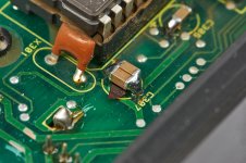
With side cutter pliers, remove the old C306 and C307. Leave the wires on the PCB as long as possible. With tweezers, and a clean soldering iron, try to remove each wire out from the PCB hole. Now you are ready to solder on the SMD’s over the clean holes. Take care about C307: There is another hole next to the one you need to solder. A circuit short can easely be made here! We used a bit of mylar tape to isolate this hole. (see the picture, we used 2x 22u, but you see the mylar isolation under the caps) Two things are important: Use a good grounded iron, and don’t melt away the flex connector.
One thing more to do: We believe that Cyrus had a problem with static discharge handling on the control panel. In countries like Australia your static buildup in your home can be dramatic: Hurting you all the time, due to a combination of draught and hot climate. There is a fair chance that you will kill your micro controller inside the Cyrus as soon as you zap it. Therefore, it might be a wise decision to ground the aluuminium front panel. In this way, you provide a ‘clean path’ for the zapped energy, to go from the front panel directly into system ground (and not into a micro controller pin). We saw a couple of Cyrus amplifiers who had this modification, so if it is not there, it is best to do this patch. Under the flex connector, you are able to push a blank wire inside a small clean aluminium gap. Remove the isolation from your wire, and push it in the aluminium gap. A drop of glue will keep it in place. Solder the other end to GND of the CB PCB, i.e. the two large soldered pads on the board is GND level, close to C307 and X301. It is the can from the IR-receiver at the other side of this PCB. Solder the wire to this point.
Herewith the CB is modified & patched. What we have used so far for the IB is:
* 1x 2u2/100V X7R 1210 Murata Digikey 490-6545-1-ND
* 1x 47u/16V SMD 1210 X5R Yageo Digikey 311-2054-1-ND
* 1x Piece of wire, 5cm.
§ Micro Controller Board
This board is the controller for the Cyrus-III: With keys and the dial you are able to select inputs and adjust volume. On this Controller Board (CB) there is the micro controller, the Z86E2 from SgS Thompson (ST). Be careful with this part: No mistakes, because damaging one pin will kill your whole Cyrus-III. One of our friends bought such an amp, useless, for spare parts only…
The front panel, the one with the pushbuttons and the dial, is designed as a plastic mould that is placed in between the aluminium frame at the front. It is simple to remove this part: Remove the flex from the Amplifier Board and then, with your thumbs, try to push out the plastic mould from the frame. Don’t push the PCB. There are some pins that will brake off, but that’s due to the age of the plastics. Don’t care about this too much: It is well designed and it will fit back again smoothly. The IB now is removed and accessible for modifications.
There are 2 electrolytic caps that need replacement: C306 and C307. For C306 it is handy to use the 2u2/100V X7R SMD capacitor, as used with the IB board. For C307 the best is to go for a 47u/16V 1210 SMD capacitor, also used in the IB already. There are two ways to remove the old and place the new capacitors: Taking the CB from the plastics, or leaving it in. We decided to leave it in place.
With side cutter pliers, remove the old C306 and C307. Leave the wires on the PCB as long as possible. With tweezers, and a clean soldering iron, try to remove each wire out from the PCB hole. Now you are ready to solder on the SMD’s over the clean holes. Take care about C307: There is another hole next to the one you need to solder. A circuit short can easely be made here! We used a bit of mylar tape to isolate this hole. (see the picture, we used 2x 22u, but you see the mylar isolation under the caps) Two things are important: Use a good grounded iron, and don’t melt away the flex connector.
One thing more to do: We believe that Cyrus had a problem with static discharge handling on the control panel. In countries like Australia your static buildup in your home can be dramatic: Hurting you all the time, due to a combination of draught and hot climate. There is a fair chance that you will kill your micro controller inside the Cyrus as soon as you zap it. Therefore, it might be a wise decision to ground the aluuminium front panel. In this way, you provide a ‘clean path’ for the zapped energy, to go from the front panel directly into system ground (and not into a micro controller pin). We saw a couple of Cyrus amplifiers who had this modification, so if it is not there, it is best to do this patch. Under the flex connector, you are able to push a blank wire inside a small clean aluminium gap. Remove the isolation from your wire, and push it in the aluminium gap. A drop of glue will keep it in place. Solder the other end to GND of the CB PCB, i.e. the two large soldered pads on the board is GND level, close to C307 and X301. It is the can from the IR-receiver at the other side of this PCB. Solder the wire to this point.
Herewith the CB is modified & patched. What we have used so far for the IB is:
* 1x 2u2/100V X7R 1210 Murata Digikey 490-6545-1-ND
* 1x 47u/16V SMD 1210 X5R Yageo Digikey 311-2054-1-ND
* 1x Piece of wire, 5cm.
Attachments
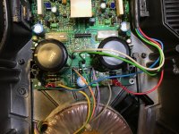
§ Cyrus-III Amplifier Board Restauration, part#1
§ Amplifier Board Restauration, part#1
This final piece of work and art we got to do is the main big amplifier board. First, unscrew the 2x2 screws of the transistor holding bracket. Then, unscrew the 4 screws at the bottom. After that, remove the fastons and desolder all the rest of the wires that go from the big toroid transformer to the Amplifier Board (AB). Also, desolder all the PSX wiring from the board {#}. Now you are able to remove the AB out from the aluminium housing. Be careful doing so, because the four power transistors (P77 of SGS-Thompson) are sticky to the sides due to heat conductive compound. With a sharp knife, simply try to release them carefully. You do not want to damage them, do not damage the back of them nor that of the aluminium housing. And you may not bend them too much. In other words: *be careful*.
The picture below is that of the wiring from most of the Cyrus-III we have seen so far. Pretty consistent, so you may use this to memorize for later. At the top you see a capacitor missing. This capacitor was removed for measurement: It should be 47u/50V but it was almost 47p/50V (rally, not a lie). One could notice that there was pressure on it long time ago. I believe in time it vented completely empty. *This* is one of the reasons to firmly overlook older Cyrus amplifier, or any amplifier: Too old, cheap electrolitics. They are just 85deg. types, low-end to regular consumer quality.
Best is to remove the old head conductive pads from the aluminium housing. Use some cleaning stuff to remove the old heat paste residues, and check if the matal still is nicely flat. In the final phase we are going to renew these heat conductive pads anyway.
{#} Side note: The PSX and the use of it:
Only one of us guys had the PSX- power supply bought together with his Cyrus-III, but to be honest I doubt the usefulness of it. Of course it was a great marketing tool at that time, but hey, try to play 5 Watt-rms audio power at both left and right sides in your living room: Most people jump out the door. So, only for extremely low efficient loudspeakers you might want to keep the PSX, otherwise… Oh, and not to forget that the toroid in the Cyrus-III looks capable of delivery of a minimum of 120VA ! ;-) We simply cutted away all of the PSX extra wiring. Purists now think: How about peak power? Well, that’s just what we are going to solve with all the patches we are going to do on the AB. On the other hand, don’t forget that Cyrus Audio - Build a better music experience are still going strong, still are making good products today, keeping up in the market. And that is not bad at all, because their pricing is absolutely very reasionable. (I have been in product development, and I know a bit of the misery to bring a good affordable and reliable product out in the field)
Attachments
Hi navelpluis
If you are still around, could you update the thread to make the restoration information complete ?
I recently bought a Cyrus III and would like to replace the CAPs in it at some point in the near future.
Can the CAPs on the main board be replaced without removing the board from the the chassis, would like to avoid remounting the transistors if possible ?
Any help is appreciated
Dear Navelpluis, Can you help ;i was reading your post i think that you have a lot old about CYRUSIII - So you kind to help or give your opinion :
Thank in advance .
Agustin
My post
'm new in this foro - And I glad to meet you
I have a 1994 CYRUS III - which is about 26 years old , and until a few months ago it worked perfectly, but it started to give an intermittent failure which consists of:
When it is turned on and the initial check is done, it blocks, not completing it and some leds remain on (Tp-cd-tuerner, volume, etc.), other times, it starts well and after one or two hours, it blocks and turns off and the same leds remain on. The only way to start it up again is to disconnect it from the mains, it will be unblocked and after a few hours it will start working again or it will be blocked.
I have taken this equipment to the old CYRUS technical service in Madrid, which has been for 20 years although it is not now, it continues repairing and checking this type of equipment; they have checked it indicating me that it is faulty:
The front micro - socket whosepannel model is: AM/EP1V3/86 (according to what I have been told about this micro several versions or updates were made - CIRUS / Missión must know it.
They cannot get me that piece but it is possible that cirus has it or some equipment of second hand that this for pieces./scrapping etc.
I had sent to Cyrus UK a note telling this problem from their support page, and they has told me that have not codes and or facilites to repair this ampolifier model anymore
ANY IDEA from US.
I love this Apmpl.
Thank you in advance for your help,
Agustin
Report Post
§ Micro Controller Board
This board is the controller for the Cyrus-III: With keys and the dial you are able to select inputs and adjust volume. On this Controller Board (CB) there is the micro controller, the Z86E2 from SgS Thompson (ST). Be careful with this part: No mistakes, because damaging one pin will kill your whole Cyrus-III. One of our friends bought such an amp, useless, for spare parts only…
The front panel, the one with the pushbuttons and the dial, is designed as a plastic mould that is placed in between the aluminium frame at the front. It is simple to remove this part: Remove the flex from the Amplifier Board and then, with your thumbs, try to push out the plastic mould from the frame. Don’t push the PCB. There are some pins that will brake off, but that’s due to the age of the plastics. Don’t care about this too much: It is well designed and it will fit back again smoothly. The IB now is removed and accessible for modifications.
There are 2 electrolytic caps that need replacement: C306 and C307. For C306 it is handy to use the 2u2/100V X7R SMD capacitor, as used with the IB board. For C307 the best is to go for a 47u/16V 1210 SMD capacitor, also used in the IB already. There are two ways to remove the old and place the new capacitors: Taking the CB from the plastics, or leaving it in. We decided to leave it in place.
With side cutter pliers, remove the old C306 and C307. Leave the wires on the PCB as long as possible. With tweezers, and a clean soldering iron, try to remove each wire out from the PCB hole. Now you are ready to solder on the SMD’s over the clean holes. Take care about C307: There is another hole next to the one you need to solder. A circuit short can easely be made here! We used a bit of mylar tape to isolate this hole. (see the picture, we used 2x 22u, but you see the mylar isolation under the caps) Two things are important: Use a good grounded iron, and don’t melt away the flex connector.
One thing more to do: We believe that Cyrus had a problem with static discharge handling on the control panel. In countries like Australia your static buildup in your home can be dramatic: Hurting you all the time, due to a combination of draught and hot climate. There is a fair chance that you will kill your micro controller inside the Cyrus as soon as you zap it. Therefore, it might be a wise decision to ground the aluuminium front panel. In this way, you provide a ‘clean path’ for the zapped energy, to go from the front panel directly into system ground (and not into a micro controller pin). We saw a couple of Cyrus amplifiers who had this modification, so if it is not there, it is best to do this patch. Under the flex connector, you are able to push a blank wire inside a small clean aluminium gap. Remove the isolation from your wire, and push it in the aluminium gap. A drop of glue will keep it in place. Solder the other end to GND of the CB PCB, i.e. the two large soldered pads on the board is GND level, close to C307 and X301. It is the can from the IR-receiver at the other side of this PCB. Solder the wire to this point.
Herewith the CB is modified & patched. What we have used so far for the IB is:
* 1x 2u2/100V X7R 1210 Murata Digikey 490-6545-1-ND
* 1x 47u/16V SMD 1210 X5R Yageo Digikey 311-2054-1-ND
* 1x Piece of wire, 5cm.
check out post #1 under
https://www.diyaudio.com/community/...schematics-of-the-later-models-wanted.155987/
for further hints and now published service manuals
https://www.diyaudio.com/community/...schematics-of-the-later-models-wanted.155987/
for further hints and now published service manuals
- Home
- Amplifiers
- Solid State
- Cyrus-III restoration project