Sansui TU-555 no stereo recepetion

Hi!

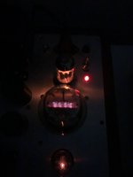
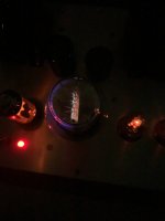
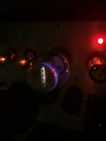
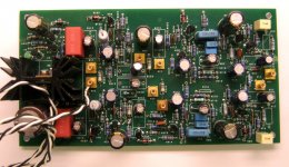
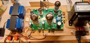
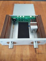
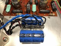
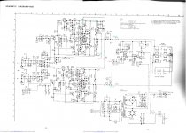
I got a little Sansui TU-555 tuner. When I first got it reception was very weak and no stereo. A lot of caps were bad so I started by changing them, touching up the soldering and replacing the famous 2sc458 transistors. The result was slightly better reception. I than cleaned the local/dist switch on the back and now reception is great only it doesn't decode stereo : I checked and double checked the orientation of the caps I changed, tested the 4 transistors on the multiplex circuit that are fine, changed the trimmer resistor, cleaned the remaining switches but there's no improvement. When I turn the trimmer resistor clockwise all the way I have a faint glow from the stereo bulb when tuning to stereo stations but when I listen to it it's clearly still mono...

10$ Recycled Sub

I get that this site is dominated by engineer types who seek perfection but sometimes the goal is improvement as opposed to perfection. What with a limited budget and available components.

My first argument was that, for the money, commercial manufacturers can build better cabinets than diy'rs.. So I purchased a JVC home theatre 19 litre sub for $7. My initial plan was to replace the 6.5-inch driver with an 8-inch driver obtained from a Tannoy sub with a dead plate amp (cost $15). However, I sold the spike feet on the Tannoy for $10 and the driver for $25 because the location of the port on the JVC would make fitting an 8-inch driver tricky.

The 150w JVC sub sounds nice, smooth and sweet but the problem was always going to be: SPL 77db / 30Hz / 6 ohms. After a debate with Chris661 and Weltersys they intimated that substantial increases in SPL could be obtained by an increase in diaphragm area.

Using only the components I have lying around this is the upgrade:

Don't you think this is a fun waste of $7?

Attachments

  • jvcp1.jpg
    jvcp1.jpg
    207.2 KB · Views: 130
  • jvcp2.jpg
    jvcp2.jpg
    179.4 KB · Views: 121
  • jvcp3.jpg
    jvcp3.jpg
    175.3 KB · Views: 124
  • jvcp4.jpg
    jvcp4.jpg
    159.5 KB · Views: 123
  • jvcp5.jpg
    jvcp5.jpg
    163.9 KB · Views: 128

Tone control input impedance?

Sorry for asking, but I have no formal math on this kind of circuit and it escapes me.

What's the input impedance of this tone network with the short vs without it?

Meter says 5k while shorted...

Beyond that, I could learn but I'd need "handholding" in this case.

Thanks as always 🙂

BTW I think I like the curves better with replacing all the 3's with 2's in the cap value.
Koda

Attachments

  • 6N1P-tone.png
    6N1P-tone.png
    25 KB · Views: 209
  • 6N1P-tone (1).png
    6N1P-tone (1).png
    25.6 KB · Views: 181
  • Screenshot from 2021-11-16 23-28-13.png
    Screenshot from 2021-11-16 23-28-13.png
    24.2 KB · Views: 174

multi sub pasive phase control

Hi,

I have a 15" subwoofer I built, using 25mm plywood (you can see the cabinet with the green grille in the image of my vintage system!) and I use this subwoofer amp BSBPV500

(they used to manufacture for REL in the early days I believe and they seem to know what they are doing ...a lot more than me!)

My brother with 3 Sonus Faber subwoofers like the sound of mine and tried the BK amp direct into the sonus subs bypassing the SF amp, and he and ended up with 3 replacing the integral amp with the BK. He uses digital signal processing to align his which I tried and did not get on with.

I made a 12" version of my 15" sub with the same brand of driver for a friend who borrowed my 15 and loved it, but his room could not put up with the cabinet size..

Anyway the preamble set's the scene for the question. When I make my subs I use a CNC shop on a full sheet of 25mm ply, and with the 12" I was able to get two cabinets out........so I have the chance to try a 2nd sub.

BUT I would rather not also invest in a 2nd amplifier if possible (which would give me independent phase control of each sub with the integral control on the amp). So is there any clever way to create a phase adjustment for the 2nd sub with a passive controller?

Thanks,

Attachments

  • Screenshot 2021-11-13 at 10.12.04.jpg
    Screenshot 2021-11-13 at 10.12.04.jpg
    267.9 KB · Views: 131

Need Help Identifying TS and RS Labeled SMD Transistors

Hi, I’m trying to repair a Vitus RI-100 integrated amplifier. This amplifier has socketed input modules, one per channel, please see picture. One channel has high DC on the output. It starts low, when initially powered on and then quickly rises to over 1V DC as it warms up. If I swap these modules between channels, DC problem also swaps. So I have it narrowed down to the module.

The amplifier works and produces sound, but I’m assuming that one or more of the transistor is partially leaking DC. And over 1V DC is extremely high.

The little SMD transistors are labeled RS and TS. I cannot seem to find what these SMD codes correspond to as far as actual transistor part numbers.

Any help would be greatly appreciated.

qSpM7Aq.jpg

1J(1Ж).., 2J(2Ж).., 4J(4Ж).., 6J (6Ж).., 10J(10Ж).., 12J(12Ж).. tubes for sale

1J(1Ж).., 2J(2Ж).., 4J(4Ж).., 6J (6Ж).., 10J(10Ж).., 12J(12Ж).. tubes for sale

Sale:
1J17B for $1
1J18B for $1
1J24B for $1.5
1J29B for $1
1J37B for $1.5
2J27L for $1
2J27P for $2
4J1L for $1
6J1B-V for $0.5
6J1P for $1
6J2B for $1
6J2P for $0.5
6J3 for $1
6J3P for $0.5
6J4 for $0.5
6J4P for
6J5B-V for $0.5
6J5P for $1
6J7 for $2
6J8 for $1
6J9P for $0.5
6J9P-E for $1
6J10B-V for $0.5
6J10P for $0.5
6J11P-E for $1
6J20P for $1.5
6J21P for $2
6J22P for $1.5
6J32P for $4
6J43P-E for $1
6J49P-D for $2.5
6J49P-DR for $4
6J49P-DRU for $4.5
6J52P for $2
10J1L for $1.5
12J1L for $1.5

Reverse eng. and making a schematic for a vintage class a/b power amplifier.

Im in the work of recapping a old vintage class a/b amplifier i own.
A Sonotron pa200 .
Sonotron as a brand existed only for a few years in the seventies until the production got moved and they changed the name to adyton. A name that are more known and are still known today .

while im waiting for parts i thought, why not make a schematic for it and make some posts along the way?
So said and done
My computer is not the latest model so not many drawing programs would not work, so i found digi-key's online schematic drawing program. So im learning to use it along the way too.
This project are mostly for fun, and maybe someone here have seen a similiar schematic. And maybe help me along the way . Who knows. Maybe modify it to sound better or do other things with it.

Im gonna post the llttle info i have collected over the years and updates of the progress 🙂

Simming the Purify Motor

Hello FEMM and COMSOL experts out there.


Anyone here willing and able to do a basic sim about the properties/BL behaviour of the Purify 6.5 midwoofer's alternating 3/4 layer voicecoil?


According to Lars Risbo, designer of the Purify 6.5 Woofer:

the winding has 4 layers but with typically 2 to 4 gaps where the coil is effectively only 3 layers. These gaps flatten the Bl(x) by reducing Bl around the rest position. This trades some sensitivity for much better linearity (the reduced mass due to the gaps compensate to some degree). the positions and widths of the gaps are found using computer optimisation of a finite element model. I hope that explains it better.

Attachments

  • PurifiAudio-PTT6-5XWoofer.jpg
    PurifiAudio-PTT6-5XWoofer.jpg
    256.6 KB · Views: 121

3 1/2 Way with Sub...My Upgrades

I have MANY drivers and amplifiers. Time to upgrade and re-arrange. On the low end; I have the SB23MFCL45-4 single in a closed box just under 1 ft^3 powered by an older Hypex DS 2.0. I will eventually add a second one but will have to wire them in series for 8 Ohms. The Hypex does great with 4 Ohms but no way could it do 2 Ohms. This won't increase my overall sensitivity I realize but I will still have twice the surface area and I'm guessing I would increase the SPL's because the Amp will have an easier load. I never have to turn the main "gain" control up past the half-way point. With all bass EQ settings, in room response goes all the way down to 14 Hz! Remarkable for a single 9 inch sub. in a small, closed box! The Hypex has a non-defeatable 12 Hz high-pass (I think 4th order?). Moving on up from there...

Homemade tube socket adaptor

Have you ever make tube socket adapter? If you have please share your ideas. Here I want to share the way I made it. The pins are pulled from wafer connector and square pin, one side is grounded round to ~1mm diameter (on press drill or hand drill). The ceramic tube socket has a small recess on top so a M3 nut can be fitted level to the socket. M3 screw hold the 2 sockets together tight spaced so the pins are 2mm apart. The square end of the pin tinned and then push into one of the socket receptor, and soldered. I wired it up for pentode strapped triode of a pentode triode tube, such as 6f12p so the tube pins are compatible with 12ax7, but G2 is wire directly to plate in adaptor so that pin 9 will be freed. It's a great way for comparing tube sonic without rebuilt another circuit.

12ax7 6f12p
1 3, 8
2 6
3 7
4 4
5 5
6 9
7 1
8 2
9 -

Attachments

  • diy tube socket adaptor-1.JPG
    diy tube socket adaptor-1.JPG
    23.7 KB · Views: 1,116
  • diy tube socket adaptor-2.JPG
    diy tube socket adaptor-2.JPG
    27.7 KB · Views: 1,056
  • wafer conn.JPG
    wafer conn.JPG
    19.7 KB · Views: 1,035

Adcom GFA-5800 amplifier cooling fans

I've got a bad fan in my 5800 and have ordered a new pair from Adcom parts, but they seem to have been delayed. So, need to find a temporary substitute locally. There's no identifying markings on the fans, so I have no idea what the CFM or rotational speed is. I have determined that the good fan will turn on at a voltage of 3.95. Has anyone else had to substitute a fan in this amp and what advice might you have? CompUSA locally has a fan of the right size, that will turn on at 4.6 VDC, so maybe that will suffice.

Suggestions for MOSFET heatsinks that will most securely against PCB?

I'm referring to the heatsinks on Q3 and Q4 on the BA-3 front-end board: https://files.diyaudio.com/archive/gallery/data/500/IMG_04151.jpg

There are no mount points for a heatsink on the board. The heatsinks I selected don't sit flush on the board, and bend back and forth as I connect test probes and such. Can someone suggest a heatsink that will mount flush with the board, or otherwise make secure contact, so that it doesn't act as a hinge on the transistor legs?

Attachments

  • IMG_3251.jpg
    IMG_3251.jpg
    875.4 KB · Views: 191
  • IMG_3252.jpg
    IMG_3252.jpg
    804.1 KB · Views: 201

Introducing Ventus

Ventus is a mostly discrete opamp. 🙂

This is a circuit designed for some DIY fun. It is based on the Diamante circuit I published a while back.

The front end is a folded cascode design and runs into a LME49600 buffer. The buffer is in the feedback loop.

A schematic is worth a thousand words.

It sounds excellent. It can drive low impedance headphones exceptionally well.

As shown it is a BAL/SE converter and take balanced input from DACs such as Buffalo or Opus.

I would suggest when using it in this way (Balanced to SE) you use a relay to shunt output to GND on turn off to prevent any turn off thump. The thump buster works well in this role.

The Ventus can also easily be setup as a classic non-inverting amplifier with single ended input. It also can be setup as an in inverting amplifier with single ended input.

Each module is a mono channel so It takes two for stereo, and they stack easily.

There is a pot to null output offset.

We have boards tested and parts are en route so these will be available very soon.

The board is tested and proven, and I love it. I have been listening to it for a week now.

Take a look.

Cheers!
Russ

Attachments

  • schematic.pdf
    schematic.pdf
    36.6 KB · Views: 738
  • pcb_small.jpg
    pcb_small.jpg
    133.1 KB · Views: 2,257

FS: Khozmo Passive preamplifier 3-inputs selector and 48-step attenuator

SALE PENDING: nice original Khozmo Passive preamplifier 3-inputs selector and Khozmo 48-step attenuator. 25K value, version with Caddock Mk132 + Vishay/Dale RN55. Very nice RCA connector.

Added bitumen vibration absorption pads inside the chassis.

See WWW.KHOZMO.COM - High Quality Passive Preamplifiers for the exact same model.

Still sell for 300$ from Khozmo, asking 200U$ + shipping + Paypal fee

Thanks
SB

Attachments

  • IMG_20211114_123105.jpg
    IMG_20211114_123105.jpg
    710.7 KB · Views: 443
  • IMG_20211114_123115.jpg
    IMG_20211114_123115.jpg
    410.5 KB · Views: 443
  • IMG_20211114_123127.jpg
    IMG_20211114_123127.jpg
    320.6 KB · Views: 435
  • IMG_20211114_123247.jpg
    IMG_20211114_123247.jpg
    358 KB · Views: 426
  • IMG_20211114_123256.jpg
    IMG_20211114_123256.jpg
    360.5 KB · Views: 426

2.1 Active Crossover

Hello greetings
trying to make this kit enclosed is the schematic as i have
little knowledge in electronics is this crossover supposed
to work with +/- 6 volt regulated dc rails
warm regards
Andrew😉😉

Attachments

6X4 Heater-cathode potential issue

I have built a tube headphone amp with following power supply.
3Ucag25.png


I got transformer with only single heater supply and a pair of 6X4 so I designed a power supply using rectifier tube with shared heater supply.
The heater supply MUST be virtually grounded using 220R (in my case). But this would cause negative potential voltage between heater and cathode which is around -280V in my case. I know the negative potential voltage of 6X4 is rated 450V which my amp should be and it's being working without problem. But this make me worried cause my people said this might cause short between heater(GND) and cathode(HV) and blow all the tubes. It just a matter of time, they said. They suggest me to get another transformer for 6X4's heater which I am going to do. (6.3V 0.5A should work well🙄)
But outside this solution. Where should I put my fuse when I'm gonna prevent heater-cathode blowing? Or any other suggestion? (including 'don't do anything' one)

Studdering mercury vapor diodes

I’m investigating a strange issue with a proven design: I’ve multiple 866A diodes that in their bridge rectification duties begin to flicker. It’s not on and off flicker, it’s as if the gas is glowing on one side of the tube then the other maybe 4 times a second.

There is no fluctuations in voltage and the music sounds fine but I feel I must not continue listening if I’ve got a tube flickering.

I’ve rotated positions so I know it’s not the hardware, it’s maybe pressure within the tube? I don’t know. I’m asking for information 😀

I’ve got a dozen 866A so I’m rotating through them to find a fourth (I have three that are rock steady if low glow...) that is steady at this point. I’ve been breaking in the candidates with a four hour burn on the heaters on a board out in the garage. All the tubes were sold as NOS. I’m still wondering what’s going on...

Please assist if you’ve got a good guess.

Is the Fostex FE126NV a direct replacement for the Fe126En?

I have a pair of Fostex Fe126En drivers in boxes I made to the OEM spec. Sadly one of the drivers has failed and my children have damaged the other one. I wax looking for replacement drivers but saw that the Fe126En has been superseded by the 126NV. Is it a true drop-in replacement that would sound at least as good in a box designed for the 126En or just a newer model in that size category, requiring a different box? (I can still obtain NOS 126Ens so just wondering whether to stick with those or if there's any benefit putting the 126NVs in the existing boxes. I don't have the time to build a new pair of boxes at the moment...)

In simple English, why do we need a custom buffer for Hypex/Purifi eval kits?

Greetings, All,

I’m obviously not electronically inclined, but I’ve recently discovered the pretty simple-to-assemble evaluation kits for Hypex NC400 and Purifi 1ET400A. I think I would like to build a couple. I’ve also seen quite a bit of activity on the need (advisability) of a custom buffer for these amps. And it looks like prominent member @tomchr (Neurochrome) has already built said buffer and is offering it for sale.

Reading through the discussions, for the life of me, I cannot figure out whether this buffer is necessary or optional and, as an end user, what benefits I can expect.

Can someone explain the necessity and/or user benefits of this buffer in simple English? Also, if highly advised, can it easily be added to the EVAL1 or GhentAudio or DiyClassD kits? Are there instructions somewhere?

Thanks

Tube PSU first cap polarity question

Sorry in advance if this is a stupid question.

In a tube rectified PSU that is CLCLC, I know the first cap size is limited by the rectifier, but does this cap need to be polar, non-polar, or does it matter? I was planning to use a 5uF cap I have on hand in that position, but it's non-polar and I can't wrap my head around what would go on in that case. Since one side is attached to ground, I think it would act like a polar cap. Unfortunately I don't have the spice/modeling skills to look at it (and I don't think PSUD has non-polar cap options).

BTW, I kinda need a cap input for voltage, but want to keep the rest LCLC. Any thoughts or explanations would be appreciated. Thank you!

Nuforce DDA100 replacement power supply

My Nuforce DDA100 integrated amplifier started to have some issues recently and I traced the problem to the (Skynet SNP-G series) 28V 120W SMPS which is buzzing/hissing quite loudly and has a faint burning smell. The amp works perfectly fine running off my bench power supply so I’d like to replace the power supply. Im looking at these two power supplies, the Meanwell EPS-120-27 no PFC or EPP150-27 with PFC. Any opinions or other options? Thanks
https://www.mouser.com/ProductDetail/MEAN-WELL/EPS-120-27?qs=Kh9WxvXxjWm29iR9914aXg==

https://www.mouser.com/ProductDetail/MEAN-WELL/EPP-150-27?qs=Uzd/wh%2BZzhAREbslZUMOsQ==

Dynaco PAS 3 selenium rectifier replacement.

Hey all!
I've just removed the old selenium rectifier in my PAS 3. I've mounted a terminal strip with 2 new 4700uF capacitors and 2 1N007 diodes. I just want to check with the experts here if the positioning of the diodes are correct? The wiring is exactly like it was in stock form as well as the polarity of the caps. As I understand it I should remove the tubes from the line stage and phono board when firing it up and checking the voltages?

Attachments

  • IMG_2977.jpg
    IMG_2977.jpg
    774.5 KB · Views: 491

TDA1549 - Marantz CD48

Hello !

I've been out of this a long long time but have been listening to and enjoying my home built stuff with a sense of pride...that it all still works !
That said, I've been getting itchy feet recently but too afraid of disturbing my successful Arcam Alpha CD with a shed load of mods I decided to do a bit of reading to see what else was out there that I could cheaply muck around with.

Not sure what you lot think but..I like the Lampizator site and the narrative sometimes makes me laugh out loud and Fikus always attempts to tell the truth...as he sees it anyway..lol

Anyway he seems to rate any TDA1549 based CD Player as pretty much ' up there ' with some expensive ones as you probably know already and it really fired me up once I'd taken a look at the simplicity of them.

So I got hooked on the teachings of TDA1549 in the Phillips and Marantz machines and bought two CD48 players for £50 ( for both )

I downloaded everything, read the lot and finally stripped the horrible thing down to a single green main board.
The 1549 DAC chip is the V out type ( as opposed to current out ) which means we can use the clean signal of the output legs ( no 4 and 7 ) of the chip straight to the rca's via a couple of coupling caps.
OK....so this is nothing new and you clever ones knew this already maybe but today I actually got round to doing it - including removing the op amp. I really enjoyed removing the op amp for a change instead of ' rolling ' them. God knows how I've wasted money on that hobby...🙄

I have listened to the player for quite a while and was surprised and impressed by the mids and treble initially but eventually found it a little forward and fatiguing compared to my very liquid and analogue sounding Alpha.

I'm pleased to say that this VERY simple mod ( 15 minutes - ish ) has jettisoned this player forward massively and so I've decided to apply several other changes to see how far I can take it.
I'll also be posting pics soon and some explanations of what I'm doing or trying to do if anyone is interested.

After all - this is how my Arcam Alpha came to be from reading the ' Arcam Alpha Mods ' thread from years back.

Please note : I'm no engineer, mathematician or clever sh... but have sufficient skills to implement additional improvements.

So, currently the CD48 has lost almost all of it's hf glare and a lot of the hardness in sound which I'm putting down to losing completely it's entire output stage of some 40 odd parts plus the crap dual op amp....
No loss in output either....same volume settings.
It sounds much better and is already matching my other machine in some if not many areas - no real analogue liquidity yet but I reckon I'll find it soon.

Next up is the diodes, all the caps, independent power to the DAC chip, improving the main but cheap 05 regulator which once powered the whole machine, eventually the clock and anything else I can think of...or you can think of if you have any advice.

If you've done one already please give me a steer....I reckon I'm on to something - and it's going to be cheap too !

Rgds

Andrew

Ultra-low jitter generators 22.5792, 24.5760, 33.8688, 36.8640, 45.1584, 49.1520 MHz

Ultra-low jitter oscillators 22.5792, 24.5760, 33.8688, 36.8640, 45.1584, 49.1520 MHz

Ultra-low jitter clock generators ГК154-П-Т, made in Russia, http://bmgplus.ru/images/pdf/pdf154T.pdf , DIL-14 packaging, 5V supply, tristate mode. The really best oscillators for audio.

Pin 1 Open or '1' level - Enabled, '0' level - high impedance, Pin 7 - ground, Pin 8 - output, Pin 14 - Pover supply.

512Fs - 22.5792 MHz, 24.5760 MHz, 768Fs - 33.8688 MHz, 36.8640 MHz, 1024Fs - 45.1584 MHz, 49.1520 MHz

52$ one oscillator

33.8688 MHz temporarily unavailable. But pllease let me know if you need this item
Alsou is possible to produse ГК155-П-Т - 3,3V supply version, but it takes very long time.

Also
Digital filter
AD1896AYRSZ - 14$

DACs
AD1955ARSZ - 10$
AD1852JRSZ - 9$

Op Amps
OP42FJ TO-99 metal can - 17$
OP42GPZ DIP8 - 9,5$
LT1122ACN8 DIP8 - 10$
AD823AARZ SOIC8 - 6$
AD811ANZ DIP8 - 9$
AD844ANZ DIP8 - 10$
AD845KNZ DIP8 - 16$
AD815ARBZ - 10$
OP484ESZ SOIC14 QUARD OP AMP - 16$
LT1217CN8 DIP8 - 6,5$


Voltage References
AD586MNZ DIP8 - 9$.
AD586BRZ SOIC8 - 9$
ADR4550ARZ - SOIC8 - 5$

EPM7128STC100-10 CPLD - 12$ Embedded - CPLDs (Complex Programmable Logic Devices) | Integrated Circuits (ICs) | DigiKey

Shipping from Russia 10$ - 12$
Paypal, VISA, other variants can be negotiated
11 oktober 2020 edited, list is aktual

Attachments

  • ГК154-(2).jpg
    ГК154-(2).jpg
    44.4 KB · Views: 1,495
  • ГК154-П-Т.jpg
    ГК154-П-Т.jpg
    80.5 KB · Views: 1,504
  • dil14.gif
    dil14.gif
    4.2 KB · Views: 1,482

Quad AlPair10M³

Hi everyone .Some while ago I had a pair of alpair 10M in a vented pair of 15 liters and because I've loved it so much I built another pair of speakers with 2 pcs each (30 Liters) . Even better , stronger powerful , just perfect . Almost perfect , because I thought my self " what if I make a new pair with 4 drivers for each speaker ? " Honestly I was inspired from Eikona but I believe it's risky to just copy that plan because it might not match ; so I guess , classic vented will be enough .Can someone help me with winISD ? I'm not lazy but I'm just not very good with it .I'm open to suggestions . Thank you

Acoustic vs. Electrical Crossover Slope

Hello, I have been a big time lurker here for a few years, but finally thought I'd ask a question for something that's been bugging me for a long time. I understand the general difference between an acoustic and electrical slope and their phase ramifications. Furthermore, I found at least one post related to this but it didn't specifically answer my question. My question pertains more to the way talk about crossover slopes in forum posts, articles online, etc. I'll use an example...
In D'Appolito's article about the Thor system (THOR: A D’Appolito Transmission Line | audioXpress) he talks about the requisite crossover slopes, e.g. on page two he says, "For the THOR TL the goal was to design a fourth-order acoustic crossover response at a crossover frequency of 2500Hz." Is he talking here about an electrical fourth order crossover, or a lower order electrical crossover that achieves a fourth order roll off when summed with the natural roll off of the driver?

BTW, I've read e.g. LDC and a couple other books, but they don't clarify this for me. I now realize that I could have learned how to read the crossover diagrams in the article and answer this for myself... thank you for indulging a bit of my laziness.
P.S. Thank you to the community in general for so selflessly sharing. I'll pay it forward one day when I've achieved the requisite level of audio DIY fu.

Compact sub for mobile dj

I just built two of Jbells SS15 using 3015LFs and am blown away. I first powered them with a Yamaha PX3 bridged at 4ohm mono and now a Behringer NX3000D limited. These are a little large (physical size, mostly height) for some of my small gigs

I now want to build a small compact single sub to supplement my smaller systems.

I am considering the Cubo 12 because I like the size of it. I could go for a premium woofer (Amp options above) to maximize the power I already have. Ideally 4 ohm.

Thoughts?

Small Class D 5.1 Amplifier Project

Hello all,

I'd like to build a 5.1 amplifier for my office to take analog signal from my sound blaster card. ATM I have a old logitech Z5500 kit and I have already replaced some speakers by Minx Mini one. I don't need an high fidelity amp I just expect something a bit better than the logitech I have now.

I am a DIY guy but one week ago, I was knowing nothing about audio. And I still don't know very much 🙂

My current project consist of various modules assembly. But I can weld electronic if required.

Here is my first try :


My questions :

- First of all, will it work fine ? 🙂

- I plan to use an active subwoofer, can I output to it an already amplified signal or should I send the raw analog signal ?

- It seem like in 5.1 schema, subwoofer use the center signal but what happen if I listen to stereo music then ? No subwoofer I guest ?

- The TPA3116 module have a gain potentiometer on each, is there a way to add a master volume above them all ? The idea would be to be able to adjust each individually (like decreasing the center) but have a master volume to simple lower the general volume.

Thank a lot if some peoples can take some of their time to give me advises.

TAD 2402 clone Crossover

I have have a active filter for my TAD 2402 clones today but will now make a passive crossover filter and has found the diagram "TSM-2" with information regards to what I need.

On internet I did find some different versions regards to components sizes for TSM-2, but I got the question about RDC for the Inductor's ?

Is there anybody that could help me with that information ?

  • Locked
Help and feedback needed please

Hi All,
I am new to all of this, never before have I made a speaker but would like to try. I don't completely understand everything but I'm keen to make this Bluetooth speaker.

This is the list of parts I'm planning on buying please can somebody tell me if this will work. I don't have a big budget, trying to keep things on the cheap side, and because it's my first ever build if I mess something up don't want it to be pricey.

ZK-1002L MINI Bluetooth 5.0 DC 5-24V Wireless Audio Digital Power Amplifier StV7 194912630292 | eBay
QTX 3 Way Crossover - 3-way 6dB, 8 Ohms, 400W 5015972052945 | eBay
Professional 8" Inch 8 Ohm Replacement Speaker Cone Woofer Driver Spare Part 5055839136586 | eBay
Black 166mm 6.5 inch 60w RMS Bass Mid Range Round Speaker Driver 8 ohms | eBay
Piezo horn speaker tweeter piezoelectric head driver loudspeaker treble H BwZSK | eBay
https://uk.deals2mall.com/18650-3s2p-12v-14000mah-li-ion-rechargeable-battery-charger.html


Should I do this with the crossover or maybe a 2.1 amp?

Please forgive me if I posted this in the wrong topic or broke any rules by posting links.

Many Thanks

Yet Another F5 V3 - measurements

Gentlemen,

there are possibly thousands posts about F5, but I simply haven't found any with definitive measurements.
My new F5 is now ready for some tests. So I have done some today.
You could find the results in the attachement.
The figures show the square wave response at 1 kHz, 10 kHz, 100 kHz and 200 kHz respective.
The output power was about 1 W at 8 Ohm/50 W resistors on both channels, Ch1 is L, Ch2 is R.
50 Ohm termination at the amplifier input was used according to generator's output to eliminate
possible ringing effects produced by fast rise times.

My results are subjectively a little different than the original showed in F5 manual.
Are they good or bad? I would like to hear your opinion 🙂

Greetings

Adam

Attachments

Gemini P-600 stuck in protection mode :-(

Hello all, I have that amp malfunctioning.

I try to understand how it works, see the schematic with some voltage (green if I think it's what expected, and red otherwise). When I plot the two channels on the oscilloscope, everything seems fine

The input stage is simple, next we have a classic VAS stage with a Vbe multiplier and a constant current source. A simple emiter follower driver and output stage. But I have no clue about what the transistor between the driver and output stage are doing. It looks like some kind of current limiter thing. I understand it tends to lower (stabilize ?) the gain of the output stage


To my understanding, 3 things are needed to release the protection : not overheating, not having too high DC offset on either channels, and… the third one is plugged to that circuit I don't understand.


What is the name of this circuit ? Would you have some resources I could use to understand ? How would you advise me to investigate the default of the amp ?

Thank you all !
With kind regards

Attachments

  • p600.jpg
    p600.jpg
    270.1 KB · Views: 130

Blame Pa!

This one should be sticky :clown:

Ok, I'm going to be first:

-He's officially responsible for me burning fingers with these multilegged fuses,
instead with my first Love - Toobz (proper ones, not those calculator display thingies, you're all using of lately :devilr: )

-He's officially responsible for me greeting The Group, with words :
"G'day, my name is ZM;
I'm ZM."

-He's officially responsible for me finding humor in (some) electronic schmtcs,
and not feeling guilt when ignoring some not having it

********************

'nuff for tonight.

next please (hoping to read some funny and embarrassing stuff here)

:clown:

2 or 3 way for warm sound jazz

Hi, i have some sonus faber grand piano, i've been using it since 2007, i'm very happy with it, i'm using it with a nad 3020.
the speaker is now loosing it's magnific sound.
i'll repair them, but i'm also considering to make a pair of speakers that sound like them. I like warm sounds and i listened to some sonus faber concertino, i think they are amazin, i'd like to build something that sounds like them, but my budget for the drivers is 600$ idk if i should do 2 or 3 way, i think 2 is better for me. I know that it's a small budget for something that it wants to sound like sonus faber, but it's what i have.
Alternatively, i can have lower alternatives, like drivers that sounds as good as kef q350.
(for the 3 way, i don't like sub, i think they are too invesive, they were whe i listened 3 years ago, i'll change my mind if you have a different experience)
Thanks for the support.

Correct way to measure MEH entry holes?

Greetings all,

in the thread 2 way Synergy inspired by SPL Runt, post # 46, mark100 argues that the distance from the MEH entry hole(s) should be measured from the middle of the hole(s) to the wave-guide to CD interface along the wave guide-wall. It seems consistent with other people's practice.

Is this because this interface is the first reflecting discontinuity causing the notch and this discontinuity has higher (perhaps even masking effect) than the reflection of the diaphragm?

If so, should this also apply to the case wherein the exit angle of the CD is matched to the exit angle of an axially symmetric wave-guide, where the discontinuity is minimized? Or, as mabat suggests extending the wave-guide all the way to the phasing plug, where there is no such a discontinuity?

Kindest regards,

M

FS: Various Tubes...

Hey all! I have some various tubes for sale as I am downsizing.

Payment with paypal is preferred. The tubes are all located in Vienna, Austria and will ship from here.

All tubes have been tested on my B&K707 Dynajet tester and in an Amplifier where applicable.

All tubes test either as new or very strong.

The list is as follows:
Matched pair of GE 6550 - Both missing guide pins - $95

Brand new sextet of Bugera branded 6550 - $130

Matched quad of Sylvania Black Plate 6BQ5 Yellow tip - $75

Matched quad of Japanese Matsishita 6BQ5 - $60

Matched Pair of Telefunken EF86 - $45

Matched Pair of Siemens Mesh Plate EF86 - $45

Matched Quad of Baldwin branded 12AX7A Matsushita - $65

Single Silvertone ST 45 dated 1938 - Tests like new - $45

Matched Pair Telefunken 6BQ5 NOS - $55 Label is worn off...

Nos American 5U4GB tubes - various brands $15 per piece. Choose RCA, GE, Slyvania, ect.

Also a very nice pair of Coral Holey-Basket Alnico fullrangers...

I will add more in the coming days.

Thanks!

300b blue glow

I've just finished building a pair of 300B SE monoblocks following the Walton Audio design (attached is a schematic). Both tubes seem to have a slight blue glow on the grid and one of them also exhibits a light blue glow around the glass. Swapping the tubes between the two monoblocks doesn't change anything, which assures me the circuits are in fact identical (no wiring errors).
B+ and bias seem fine to me, around the required voltages:
- B+ is at ~420V
- Bias across 880Ohm resistor is 71V (=80mA if my math is correct)
The tubes in question are a new matched pair of 300B from Electro Harmonix (non gold).
Filament voltage for both 300Bs is low at 4.3V but that's an issue with my DC regulator which I will address shortly.

I've attached pictures of both tubes:
- fine.jpg shows one of the tubes without blue glow on the glass which has some light coloring on the grid
- blue1.jpg and blue2.jpg show the other tube with some blue glow on the glass as well as on the grid

My question are:
- Is this normal? I've heard blue glow on the glass can be a bad vacuum which worsen performace, but the tubes have been matched (and tested) at factory so I guess they are still good for operation. Since the tubes are brand new with less than 30 minutes on them I can ask for a replacement hopefully.
- Are my voltages too far off from the schematic and will I need to change something in my power supply design?
- Could the low filament voltage be the culprit?

In the meantime I'll keep the amplifiers powered off to avoid any damage.
Please ask any additional data if necessary.

Attachments

  • schematic.jpg
    schematic.jpg
    80.8 KB · Views: 374
  • fine.jpg
    fine.jpg
    40.8 KB · Views: 369
  • blue1.jpg
    blue1.jpg
    51.2 KB · Views: 339
  • blue2.jpg
    blue2.jpg
    50.7 KB · Views: 353

Fully tube regulated PSU

In some thread I remember some guy has said that he found lots of radar gear and it all had fully tube regulated (6080 double triode), LC input PSU.
I was keen to find those gears schemos to see what the military could do for us audiophiles in terms of clean and stable power supplies, but was unlucky to find them. Maybe someone has hints where to find them. That would be nice!

Attachments

  • Preferred.jpg
    Preferred.jpg
    48.1 KB · Views: 666

QUAD ESL-63 (988-2905 etc.) on steroids

I will cover som facts that you didn´t know about one of the most famous speaker ever.. hopefully someone else will contribute with some hard core information as well? Lets se... 🙂
Everyone know that this speaker is VERY different from all other speakers ever made!
There is no other speaker that comes even close in how it´s designed.
I have had those since the beginning of 1990´s and now I have 9 pairs.
I also have different types such as: Beveridge 2SW2, esl 57, DM70, Stax headphones..
Together with MTaudio i have refurbished many speakers and done some experimentation, which gives this thread the name "steroids".
-Is it possible to make this speaker better?
-Is there compromises made from the beginning?
-Is the newer ones (2912) different and better than 63?
-Does 989 and other 6 panel QUAD´s have a built in bug?
-Why did it take over 25 years for mr Peter Walker to develop this speaker?

I will cover some facts that you didn´t know.😱😱
First a measurement of the square wave response of a sligtly modyfied ESL63
As you can see it´s not perfect.. but in the video I will show you what happends when the microphone is moved around 1" or 2,5 cm...

Attachments

  • QUAD.jpg
    QUAD.jpg
    849.5 KB · Views: 1,014

Monsterizing a Denon DP-80

I had been aproached by a fellow audiophile who wanted to make a killer TT
without breaking the bank (sub 5000 euro).
He was already using a nice german made turntable (that many would dream of)
but he (and I) thought that his sound was not as it should be.
He had tried many cartridges and three phono stages but he was still unhappy.
After listening to my analog combo he decided to completely alter his set up.
The limit was 5000 euro all included (turntable, arm, cartridge,phono stage).
If you want to make something really good for this kind of money,a nice plan
is paramount!
Since his main part of Lp's were 70's-80's rock, i proposed to him to escape from the belt driven camp and move to the DD one.
For some strange reason DD ones always seem to me to nail down rock/dynamic music better than belt driven turntables.I have some ideas on the subject but i will not discuss them now...
At first he thought that this was a stepback but he changed his mind
when i showed him what i was considering.
The Denon DP-80 is an 80's workhorse with known good and bad points.
The good ones:bidirectional servo,a 3 phase out motor that can move mountains,a very well damped (two metal part with interdamping layer) platter,easy layout,quality construction.
The bad ones : only 100VAC (Japan only version),hard to find a clean well maintained unit,the underside is prone to sound reverberation...
We had to find the "naked" version that was sold to radio stations
or audiophiles who wanted their own type of plinth because i was going after a design that was going to cure as many as possible of the known flaws.
So our quest for finding such a nice unit started ... and was fruitfull after
3 months or so when a nice specimen was bought through ebay from a german lady whose's late husband had an eye for good things audio
(judging from what else she was selling).
He had quite a collection of turntables and the Denon obviously was sharing duties with other sources which meant that it was a low hours unit.
It arrived at my office nicely packed,totally unscratched,with the Denon manual and the cutout schematic!
Total cost:1000 euro.
You have to see and hold one of these in your hands to fully appreciate
the quality of construction involved.My friend was stunned with its
flying saucer looks and it's sheer size!
Fot those not familiar please see the pictures:
a)Denon DP 80
b)Denon DP-80 on thevintageknob.org

  • Locked
[NEW Topping] What chip would be hiding inside) open bets)

[NEW Topping PA5] What chip would be hiding inside) open bets)

Hi amigos,

While Allo is about to release his TPA3255, Topping unveils its new Power amp , leaving the PA3S behind ....

Here the first measurements ) Open bets about the chip ? MA5332MS new Merus chip ??? ....

leDF59X.png


---------------

As reminder, Allo TPA3255 first measurements :

PS : I got the first picture ) I can already say, it is a balanced TPA3255 with Gain and inputs selector.

THD+N 5W , 1Khz 0.00014
THD+N 100W 20-20Khz 0.0097
THD+N 10W 20-20Khz 0.0091
SNR : 117DB

PS95-8, why not sounding good?

Hi all.

I'm using a ZK-TB21amp @ 12V and aiming for 8W. I have a sealed .1 ft^3 box and some songs play well but for part of songs it sounds like a detuned AM radio.


wX735q3.jpg


I get the same sound with another smaller box and also with no box (low volume).


When adding a basic filter with what I had at hand, 0.33mH and 10 Ohm in parallel it improved, but I still get the AM sound.

I wonder what I am doing wrong. I better get it to work because I got a few of them.


Regards.

Hammond PT 5V CT winding hookup?

Just want to make sure I don’t blow out a transformer winding so please allow me to run this by you to make sure. I’ll be using a Hammond 378X power transformer for my KT88 tube amplifier and I have a question about the filament windings.

The amplifier uses two KT88 tubes for the output which I’ll supply AC heater current to using the 6.3V CT 6A filament winding, with the CT hooked to chassis/GND.

The small signal tubes I’d like to supply DC heater current to, by full bridge rectifying the 5V CT 3A filament winding as obviously 5x1.41=7V, which with either a diode drop or a series resistor gets us right at 6.3V.

The question is regarding the connection to chassis/GND. Can I connect the CT on the 5V CT 3A winding to chassis/GND or is it better to leave CT floating and connect either end of the rectified DC voltage to chassis/GND whichever gets the least amount of hum?

Hammond 378X transformer
378X - Hammond Mfg.

Looking forward to your replies, thanks!

Attachments

  • D47C658F-D390-4472-A14E-4E270F67297D.jpeg
    D47C658F-D390-4472-A14E-4E270F67297D.jpeg
    34.2 KB · Views: 153

Need your help in choosing an AMT twitter

I am designing studio monitors for myself and am faced with the problem of choosing twitter
i have 2 variants:

1. Dayton Audio ES104AMT-4
Dayton Audio ES104AMT-4 AMT Esoteric Series AMT Tweeter 4 Ohm

2. Dayton Audio AMT2-4
Dayton Audio AMT2-4 Air Motion Transformer Tweeter 4 Ohm

I already have a woofer, it will be Dayton Audio ES180Ti
Dayton Audio ES180Ti-8 7" Esoteric Series Woofer 8 Ohm

it's hard for me to choose twitter. can anyone please help?

D'Appolito with asymmertrical crossover

Hi

I'm interested in trying a passive, asymmetrical crossover for fixed height listening.

Only have basic c/o experience (did a SEARCH and couldn't find the answers)


I wish to make a relatively small HF section using a pair of Tang Band 3" neodymium drivers (like TB W3-1364, 86dB sens) I have on-hand, crossed over at 3.5kHz to a pair of small planar tweeters(91dB sens), also on-hand. The sensitivities should match well with the two W3's in parallel. The inter-driver distance is approximately 3.25 inches.


Due to smooth, extended response of the W3 and high low end cutoff of the planar, I was wondering if I could pair a 1st Order(Butterworth) low-pass with a 3rd Order (Butterworth) high-pass both filters selected for the 3.5kHz c/o transfer? I'm hesitant to use 3rd order LP on the W3, because I'd prefer to keep the mid-band filter simple (i.e. fewer reactive elements).


I have read about successful designs using asymmetrical crossovers, and that both 1st order and 3rd order filters have 90 degree phase. (I also read about someone combining 2nd a order L-R with a 3rd Order Butterworth, but heard that the driver polarities were reversed, which I'd like to avoid).


Anyone have experience doing this, and if so, can you give any pointers?


Thanks

Aiyima A07 TPA3255 power consumption/output to speaker

I use Aiyima A07 amplifier with black brick adapter 32v 5A.

Then I bought a multimeter and kwh meter because I am curious how much power does it need from the wall, and how much power does it output to the speaker.

My default listening volume is at 9-10 o'clock, mostly 9.

KWH meter shows Aiyima A07 + 32v 5A adapter is only using 4 watt of power from the wall.

Checking AC Voltage going thru the speaker reveals only 0.6V (playing 50hz sound wave), and only 0.2-0.4v playing music.

We can calculate watt to speaker from the voltage acquired from multimeter, right ? Using P=V^2/R ? if it's 0.2-0.4v playing music, then average is 0.3v * 0.3v / 6ohm (wharfedale spkr) = 0.09/6 =0.015 watt.

Why is it so low ? Is there something I'm missing ?

Translinear Current Mode amplifier (?)

Shearching on aliexpress i found this amp

it claims to:

"buffer stage uses cross-conductor current mode patented technology, high current class A output. output stage and load uncolupled capacitor"

ok i know nothing about electronics. this have any sense?

all we know chiness and her marketing...

as i know, specs seems not too bad. anyone knows something about this?

priced arround 310€ with shipping.

Hbc444b7cb1514a63af4bcc102a4b2ef3S.jpg


Recommended load impedance: 4-16Ω
Output Power: 70Wx2 RL=4Ω.THD+N=0.8% || 40Wx2 RL=8Ω,THD+N=0.6% || 25Wx2 RL-16Ω,THD+N=0.4%
Output voltage swing: 40Vpp
Distortion(@1kHz): 0.07(RL=4Ω, G=0dB, IN-0.6rms) || 0.006(RL=8Ω, G=7dB, IN=0.6rms) || 0.002(RL=16Ω, G=14dB, IN-0.6rms)
Frequency response:5-220KHz
Input sensitivity: 15.0Vrms(PO=Hi, G=0dB) || 4.3Vrms(PO=Hi, G=7dB) || 2.0Vrms(PO=Hi, G=14dB)
Noise: 2.0uV(G=0dB, RL=4Ω) || 3.4uV(G=7dB, RL=8Ω) || 9.6uV(G=14dB, RL=16Ω)
Gain: 40dB
SNR: 130dB(PO=Hi, G=0dB) || 121dB(PO=Hi, G=7dB) || 106dB(PO=Hi, G=14dB)


H9080bf4314334d39b5c66df33c66a87aV.jpg


Hfa1b7c57ca01450fbc91928c5430c62aO.jpg

Bipolar AIO RIAA + Lineamp

Attached is a picture of a new project combining 2 channels of RIAA preamp plus line stage on a single PCB. The RIAA stage is passively equalized, and is based on a simple bipolar 2-transistor gain cell w/feedback boasting impressively low simulated THD. The line amp uses a beefed-up version of the same 2-transistor gain cell with a gain of 5X. The board is all stuffed and ready for power-up and characterization. The board also incorporates a discrete shunt regulator that takes a +40V or so input voltage and generates a +30V regulated output to power all stages.

Attachments

  • Img_2984.jpg
    Img_2984.jpg
    251.2 KB · Views: 750

F5 increased gain followed by failure

I have an F5 I built a few years ago (no P3, 24 V rails, single pair of MOSFETs on each channel, current protection circuit, legit Toshiba JFETs, 0.47 ohm source resistors). It was biased at about 1 amp. As in the original schematic, I used 4 X 100 ohm feedback resistors and had a gain (voltage) of about 6. The amp worked fine.

I decided I would like to double the gain of the amplifier. I checked the gain using a sine wave input (1 volt RMS) and 8 ohm load on speakers with my scope and had a perfect waveform out with a gain of 6 on the left channel. I didn't check gain on the right channel, but removed both boards and changed out the 100 ohm resistors for 220 ohm 3W resistors.

I confirmed that both boards had good soldering, and resistance across the set of new feedback resistors read about 58 ohms, which was about what was expected. I then reinstalled the boards, confirmed good voltage from the power supply on both sides. Neither board required any change in settings of p1 or p2, and offset remained < 2 mV, and bias was at 1 amp.

So....I checked gain on the left channel using the same conditions as before changing resistors, and the gain was slightly over 12, just as expected. Great waveform.

But then I checked gain on the right channel, and found it to be 17.4 with a perfect waveform. Triple checked. Powered down the amp and rechecked resistance across the feedback resistor network and it was fine. Took each resistor out of circuit and each measured fine. Repowered up and again had a gain of 17. I added two more 220 ohm resistors in parallel with jumper leads and gain fell to 12. I removed the two extra resistors and it rose back to 17. This was followed shortly by a sudden deterioration in waveform on the output of the right channel (sine wave in, strange-looking non-sine wave out) with no gain whatsoever. The waveform was not showing oscillation (that I could recognize). No sparks. No smoke. Source resistors not hot. MOSFETs were not hot. I turned off the amp and removed the board. Source resistors look discolored but measured fine. MOSFETs checked OK out of circuit. JFETs checked OK out of circuit. Feedback resistors look fine and measure 58 ohms across all four in parallel (as does the good board). I rechecked voltage on the power supply and it is fine and smooth DC on the scope.

I'm not sure exactly what failed, but I am simply building a new board, as I have all the components and some spare boards. But I was looking for some opinions.

1.Have others encountered unexpected increased gain prior to failure of an amplifier circuit, or is this highly unusual?

2. Could the gain have always been high (say, 9), but I had never checked it before, and thus was unaware of it? If so, how could this have been if all resistor values were normal and I had legit Toshiba JFETs.

3. Would increasing gain, alone, in this amplifier with 24 volt rails be expected to cause instability and oscillation?

4. If it was oscillating prior to failure, could that have accounted for the high gain, despite what looked like an excellent wave form (and source resistors and MOSFETs that did not feel hot - measured at 94F)?

5. Any suggestions as to what happened?

If I need to make a modification, such as addition of a low value cap across feeback resistors, I'd rather do it now, but really didn't anticipate this would be a problem. Of note, I have another F5 with 32 V rails and 4 devices per channel (cascoded) with a gain of 12 (4 X 220 ohm feedback resistors) that works great without any suggestion of instability.

Thanks,

Steve
Phoenix

Alpine MRV T707 not powering up

Hi all,

I’ve finally gotten around to replacing the dead outputs and leaked primary side capacitors in my old T707 and it won’t start up.

The power light comes on, a get a sawtooth wave from the tl494 but the output square wave won’t stay constant. It powers up in little burst and then dies down again.

Im pretty sure the output section is fine, any pointers on why this could be?

Would appreciate a service manual if anyone has one.

ADAU1466 + ES9038Q2M Pi Hat DAC not working

I am working on a project with raspberry pi streamer

and adau1466 DSP (ADAU1466 Core Board Designed for SIGMADSP Engineers Audio Maker DIYER sz898 | eBay)

and es9038q2m Pi hat DAC(ES9038q2m DAC Board Digital Broadcast I2S 32Bit/384K DSD 128 for Raspberry Pi | eBay)

I managed to get the DSP working via USBi programmer and I wanted to test I2S communication to the DAC using a sine wave generator in sigma studio.
The oscilloscope showed proper output on the I2S outputs of the DSP, but the DACs do not deliver proper output and lock led is not lit.
I wonder if these DACs are supposed to work standalone or if they can only be combined with a Raspberry PI. I used the same I2S pins on the DACs GPIO Port as described for the Raspberry Pi GPIO Port.

But this does not work. I cannot make the communication between DSP and DAC work. Has someone tried a similar setup successfully or has anyone an idea why this setup is not working?

Thanks

Building Transmission Line for SS 15W8530K00

Hello,

I am going to build a 2-way TL and would like to get some advice and suggestions. The midwoofer is Scan-Speak 15W8530K00 with parameters: http://www.tymphany.com/scanspeak/data/15w_8530k00d.htm

I have searched through the internet and found very helpful and proffessional sites like Martin J. Kings and t-line.org. Now I am wondering which would be the best design for these midwoofers, TL length, damping, driver placement, foldings etc.

All opinions and suggestions are welcome 🙂

Ray

SEE: Severe hum

I have fired up my SSE and there are a severe hum in the speakers, I still hear it when I leave the room with the door open.

This is my first build and the setup are:
  • Power: Hammond 374BX
  • JJ 5AR4
  • JJ 12AT7
  • Russian 6L6GC equivalent (see pict)
  • OPT: Edcor GXSE15-8-5
  • No choke, R1 = 150 Ohm
  • Speakers: No name 8” + 1” tweeters from the 1995-isch.

The amp are now configurated in triode without feedback (see pict)
The board are grounded via the PCB together with the zero point of T1, the center of 375-0-375.
Incoming signal are grounded via the PCB at the IN-connectors (pin 2 & 4)
Speakers are grounded via the PCB at connector T2&T3 sec
I have not grounded the power and OPT shields, it is on my ASAP to-do list.

Measurments:
  • B+ = 454 V
  • R17/R27 = 680 Ohm, wired to the outside of the PCB for easy exchange during the test period
  • U_R17/R27 = 35 V
  • I = 35/680 = 52 mA
  • P = (454-35)*0,052 = 21,5 W
  • VAC in idle on the OPT-sec are 24 mV on left channel and 54 mV on right channel, measured with my DVM.
My oscilloscope are not sensitive enough to measure mV and are only rated for 50V. Will try primary side of OPT with DVM before I hock up the oscilloscope on that side.

Things I consider to try out, in specific order
  • Ground the casing of transformers
  • Twist power wires (5, 6,3 and 375 V)
  • Add a capacitor at T1 red/yel-GND

Will negative feedback help?
Shifting the sec of OPT?
I’m considering a choke. However are this related to cost (I have already exceeded my budget) and lead time, if I order today will I not receive it until next week, the weekend will be spoiled. Therefore is this not my primary solution, more like a backup.
Anything else, what have I missed?

fk2wbWWVJUyju6Qe6


J4uemj2DfdFCvFAQ8

Attachments

  • 20211103_213406.jpg
    20211103_213406.jpg
    932.7 KB · Views: 164
  • 20211103_220635.jpg
    20211103_220635.jpg
    390 KB · Views: 129
Projects by fanatics, for fanatics
Get answers and advice for everyone wanting to learn the art of audio.
Join the Community
507,758
Members
7,887,202
Messages

Filter

Forum Statistics

Threads
406,170
Messages
7,887,202
Members
507,758
Latest member
Cindy