Either a shared neutral/point or a ground.
http://web.lerelaisinternet.com/reovariac/Documentation/Reovar_RRT.pdf
You can use a multimeter to find that out 🙂
http://web.lerelaisinternet.com/reovariac/Documentation/Reovar_RRT.pdf
You can use a multimeter to find that out 🙂
I do NOT find it a neutral point or ground since it´s shown as a TAP in the whole winding.
I would expect that at one end or the other.
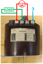
Original label shows:
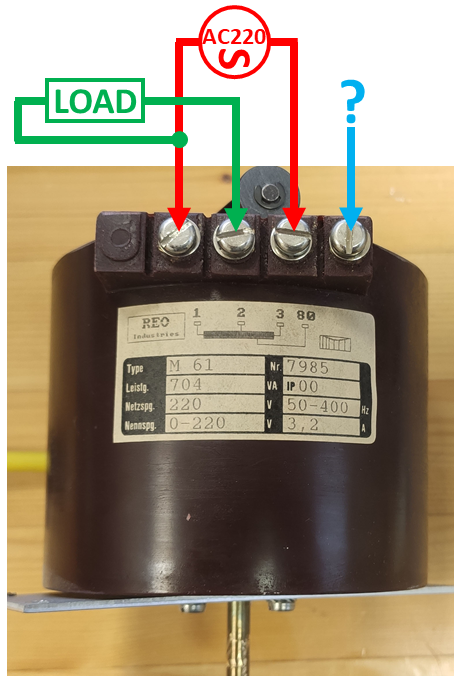
A whole/continuous winding from 1 to 3, so I agree that is where you attach 220V mains.
"2" looks like a sliding wiper/variable tap.
"80" looks like a fixed tap ... 80V ?????
IF it´s a correct interpretation (user manual does not clarify that) I would :
* connect 220V mains 1-3
* Hot to "1"
* Neutral to "3"
* connect load 2 to 3 , not 1-2 as drawn, reason being it´s safer connecting at least 1 load end to neutral, not always floating at some hot voltage.
* when connected that way, measure voltage present from 3 to "80" and post results.
There are other possibilities, but this one strikes me as simplest - safest ; in any case measuring is king.
I would expect that at one end or the other.
Original label shows:
A whole/continuous winding from 1 to 3, so I agree that is where you attach 220V mains.
"2" looks like a sliding wiper/variable tap.
"80" looks like a fixed tap ... 80V ?????
IF it´s a correct interpretation (user manual does not clarify that) I would :
* connect 220V mains 1-3
* Hot to "1"
* Neutral to "3"
* connect load 2 to 3 , not 1-2 as drawn, reason being it´s safer connecting at least 1 load end to neutral, not always floating at some hot voltage.
* when connected that way, measure voltage present from 3 to "80" and post results.
There are other possibilities, but this one strikes me as simplest - safest ; in any case measuring is king.
Yes, to measure is to know. You don't even need to connect a load, just measure between [3] and [80] that will tell all.
Jan
Jan
Most variacs have that additional tap just below the full winding for use as a "boost" range.
In other words, if Input AC is fed into 1 and 80, instead of 1 and 3, then turning the wiper up full will supply more than the input voltage by about 20%.
As with any variac used for amp testing, a good idea is to include a dim bulb circuit after it, with a switch to optionally short out the bulb.
I'd also advise using a 5 amp fuse for that variac.
I got busy and made my own snazzy variac, with switchable dual dim bulbs and a +/- DC power supply as well a custom meters.
Attachments
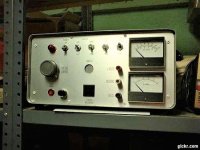
I use a isolation transformer with mine, I keep meaning to add the lamp but have just watched the amp meter. Usually I have already tested my amps on my dc power supply am just powering the powers supply by itself.
Bill
Bill
- Home
- Amplifiers
- Solid State
- Variac for amps