ICEpower ASC 300 class D

To control my corner horn speaker18, I wired an ICEpower ASC300 Class D amplifier according to the information in the official Data Sheet Version 0.1 Preliminary.
It works with a slight hum. If the input is short-circuited, it is hum-free. What did I do wrong? Should I put a shielded case around it? My preamplifier is an AudioNet multichannel A / V preamp. It is about 2 meters far off.

High pitched electrical noise

Hi,

dunno if i'm posting this in the right forum, sorry if it's the wrong place.

here's my problem;
I've got this strange high pitched sound randomly coming out of any guitar/bass amps i use in my studio, with or without an instrument plugged into it.

Anybody recognize this kind of parasite and know what to do against it ?

Thanks !

Attachments

  • AMP NOISE.mp4
    47.8 KB

FS: 8' Mapleshade Double Helix *PLUS* version Speaker Cables $175

SOLD SOLD SOLD SOLD: 8' Mapleshade Double Helix PLUS version Speaker Cables $160

SOLD: 8' Mapleshade Double Helix PLUS version speaker cables for sale. Please take a look at all the photo's. I had these cables in main rig and sound great, check out all the reviews. Retails for $490 (v.2)......................Price: $160 to you paid via PayPal.

I can attest to what Mapleshade's description says (see below) of these cables in my system and compared to my other cables. These are approx. 8 feet long, stereo set.

I have extended the length of the contact area on the speaker side (1-1/2" long) to bridge my Totem Mani's bi-wire posts. I fed the cable into bottom (woofer) post up to tweeter post so I wouldn't need to add a jumper; it worked well but can easily be trimmed down for single set of posts. Please check out all the photo's, the cables have not been abused, have about 500 hours on them. I received them with heat shrink on them at the ends like you see in the pics. The ends do show some marks from speaker posts but the rest is clean, stored either coiled (like in photo's) or used in a low traffic area. Actually had them connected not touching anything and suspended above floor with no sharp bends.

Will be properly packed up and mailed right away via USPS with tracking number within the United States. I have perfect seller feedback on other sites (ebay, Audiogon...etc), just haven't sold here yet. I'm happy to provide you with those sites feedback and feel free to ask me any questions. Thanks for looking.

This is the more expensive PLUS Upgrade version using specially-treated copper conductors with proprietary stress-relieved metallurgy. For fans of well-recorded acoustic music, small group jazz, or chamber music, we recommend add PLUS Upgrade without hesitation. Listening to loud, compressed recordings, the improvements will be audible but much more subtle.

PLUS lowers the soundstage noise floor, resulting in a quieter, blacker background. This makes the most difference in quiet passages: held guitar or piano chords sustain longer and resonate more clearly as they fade into silence. Newly discovered details and nuances emerge from the negative space of the music on good recordings.


51700669324_6b6daf5275_b.jpg


51700882075_686564acca_b.jpg


51700669034_a9efb28db4_b.jpg


51699995091_b7732922cf_b.jpg


51700273418_9119ceef3d_b.jpg


51701351477_46fac1cb09_b.jpg


51700669139_a60f61ff2c_k.jpg

SI5341 PLL

SI5341 is a Ultra Low Jitter , Any-Frequency, Any Output Clock Generator

When input a 10MHZ clock , Output 22.5792MHZ or 24.576MHZ , Deterioration less than 10dbc/HZ with 1HZ

Many very cheap SC-CUT OCXO has -90dbc/HZ 1HZ phase noise , when 5dbc/HZ be degraded by SI5341 , It also has -85 dbc/HZ 1HZ , much better than CCHD957 ( CCHD957's 1HZ is 65dbc/HZ ) .

Attachments

  • S1.jpg
    S1.jpg
    48.1 KB · Views: 157
  • S2.jpg
    S2.jpg
    61.9 KB · Views: 158

First passive crossover attempt, comments appreciated

Howdy folks, am working on my first passive crossover design. Using a Celestion CDX1 1446, JBL clone 12" waveguide (Dayton), and a Visation 300w 12" woofer, 78L ported cabinet tuned to 35hz.

Pictures are the current schematic with response and impedance, then the response blown up, and then the polarity inverted on 1 driver to show reverse null.

I've been told the inductor on the tweeter should be under 1mH, however if i go lower than 2.7mH as shown, i get an increasing spike in response at the crossover, and it throws the phase out a bit. the impedance spike is quite high, however on the low side impedance looks good bottoming out at around 5ohms. The amp i'll be using is rated to 2 ohms.

Would be good to bring the level's down a bit on the woofer from 400-700, and also the peak at 1600-2000hz if possible - appreciate comments.

Thanks 🙂 fun fun.

Attachments

  • Xsim schematic 1.png
    Xsim schematic 1.png
    341.8 KB · Views: 105
  • Xsim schematic 2.png
    Xsim schematic 2.png
    243.4 KB · Views: 102
  • Xsim reverse null.png
    Xsim reverse null.png
    250.7 KB · Views: 112

3 thread notifications were flagged as Spam

Don't know if this isn't related to the migration, it's never happened before. Now it happened 3 times in 1 day

The usual emails I get stating there's a new response to a thread I subscribed to automatically were flagged as spam and sent to my spam folder. This is chrome running on an android tablet.

It was flagged because of the address "webmaster@diyaudio.com"

Here's part of the text of the email
Dear rif,

dangus has just replied to a thread you have subscribed to entitled - simple solution needed: how to listen to (digital) music in 2021 - in the Digital Source forum of diyAudio.

This thread is located at:
https://www.diyaudio.com/forums/dig...ion-listen-digital-music-2021-a-new-post.html

Audiomeca Mephisto skipping - fixed

Hello all,

First post here and thank you to all the community - you have inspired me to attempt repairs that I would not have dared to take on...

Apologies for the long post to follow.

The problem: my faithful Audiomeca Mephisto I transport had started skipping - sometimes whole seconds at a time, other times just a "click" and a subtle sense of a note missing or timing being off. The issue was very apparent on the first couple of tracks, where the CD is spinning fastest, but sometimes it would appear throughout the record, making music totally unlistenable. It also had problems recognising discs, coming up with an error until switched off and left to cool for a while. The Mephisto is 14 years old - I have had it for 12 - so the first thing that came to mind was faulty tracking due to pickup wearing out.

I have to admit that I brought the machine to a dealer asking to fix it - it was returned three weeks later, saying "it needs a new pickup, but we can't source CDM9 pro anymore". Rather than throwing away the thing, I decided to try to fix it myself using a CDM9/44 mechanism which I ordered (second hand) from Grandata... after all, I read over here it was easy to replace the pickup head and they are supposed to be the same unit.

I started to take apart the machine, and after removing the top cover I noticed that the foam pads on which the whole mechanism is suspended were sagging. This prompted a bit of experimenting, ending with the conclusion that actually the pickup was fine - but the servoes could not cope with being on a slope...

I sourced some closed-cell rubber foam, 10mm thick, cut five 25mm square pads (the originals are round, but my skills in cutting foam are very far from Giotto's), drilled them with a 6mm bit and roughly shaped them to avoid interference with other parts. Two of the pads are glued to the acrylic "joists" that hold the lot up - superglue seemed to work fine on both the rubber and the acrylic plastic.

Replaced pads, paid a lot of attention at keeping things level, lubricated the pickup pivots, and voila - the player now reads all discs, does not skip and is back as good as it always was.

Total cost: about 3 hours of work, €5 for the rubber (I bought a lot more than I needed) and £30 for an unused CDM9/44 mechanism - I may keep it just in case the laser ever does wear out!

Lessons learned:

1. Don't trust dealers. Too many vested interests.
2. The Mephisto is fitted with a CDM9/44, not a CDM9pro
3. Sometimes the very simplest things work
4. I still cannot take the CDM9/44 laser pickup apart...

Full wave doubler question

With the Delon full wave doubler circuit below... Does increasing the capacitance give better load regulation stability up to a point? I'll be following this up with an RC filter and regulator so ripple reduction isn't my concern. But was wondering at what point increasing the capacitance in the doubler itself ceases to be worthwhile. The total load I want to keep at 50% of what I know the doubler can provide anyway so I'll size the transformer appropriately.

So is increasing the capacitance here to say 1000uF going to be an improvement, a problem, or "makes no difference" stability wise for the final amp sag-wise?

Voltage-Doubler-Blog-03.png

Elliott Sound Project 101 Rev C

Hello Folks. I think this will be the last DIY amp I build. In the last two years this will make 4 amplifiers and 2 pre-amps. MX50SE, L12-2, L20SE and ESP project P101. ESP project 97 pre-amp and Doug Self Preamp from Linear Audio #5.

This is the P101 rev C. MOSFET Amp from Elliott Sound.

I put it together with all his recommended parts. I ordered the power MOSFET from England, 40-0-40 625va Toroidal from Parts Express, Heatsinks from HeatsinkUSA, purchased the Soft-start and speaker protect boards from DIYaudio. I had a Velleman K4305 VU-Meter kit.
I built the Power supply Filter board as recommended from ESP and added a 12vdc regulator that gets fed from the Pos Rail to power the VU-Meter. I added RL circuits to the outputs using 1.2uH air coils and 10ohm/5watt resistors.

Some spec’s…
Set the bias to 20mA per pair.
Power supply…+60.5/-60.6
20mV ripple across +and- power supply
DC offset: Lt 1.2 mV / Rt 1.1mV
Total weight… 26 lbs.

Elliott is correct, It does sound very good.

Glad to try and answer any questions about the build.

Scott 😀

Attachments

  • 1.JPG
    1.JPG
    908 KB · Views: 1,432
  • 2.jpg
    2.jpg
    391.2 KB · Views: 1,371
  • 3.jpg
    3.jpg
    458.4 KB · Views: 1,622
  • 4.jpg
    4.jpg
    448.9 KB · Views: 1,445

Has anyone tried this TPA3116D2 X2 board from China?

I had a free project chassis so I got this cheap TPA3116D2 board on eBay from China. I was surprised at how well it was put together, and its sounds is not bad. I need advice on upgrading the output filters. It has quite a bit of hiss. As usual, my intent is to take it to the next level. To be candid, for $32, there is hardly anything complain about.

Attachments

  • IMG_3444.jpg
    IMG_3444.jpg
    309.4 KB · Views: 336
  • IMG_3431.jpg
    IMG_3431.jpg
    195.8 KB · Views: 362
  • IMG_3458.jpg
    IMG_3458.jpg
    295.1 KB · Views: 321

QSC CX12T 70V transformer removal

I have a couple of QSC CX12T amps that have massive 70V output transformers in them that are horrendously heavy. I only use the 8 ohm output and would like to jettison those hunks of iron if I can. The 8 ohm output comes directly from a connector on the main board, while the transformer is fed from a different connector on the board. Just wondering if I can just completely disconnect it without affecting the normal 8 ohm operation. Has anyone tried this?

Forte Model 5 Seconday Voltage?

Forte Model 5 Transformer Seconday Voltage?

Fellow Earthlings,
My Forte Model 5 appears to have blown it's transformer (zero voltage at the two blue wires from transformer to rectifier). Easy replacement, but I don't know the secondary A/C voltage.

The transformer is an Avel Lindberg Type 40/6217/2 manufactured in 1990

- a search for that netted nothing, and a call to the phone number listed on the AL site got a response from a personal cell phone.

The 1A schematic shows a dual output secondary of 57V, and 36V DC at the boards, but I don't want to depend on that, and of course, M5 schematics are non-existant. And before you mention it, John Soderburg is no longer is business or available.

So, having said all that, does anybody know the secondary voltage, and/or have an M5 you could measure? If you are measuring, please put an insulator over the tops of the PS capacitors and be careful with your probes - that rectifier is all the way at the bottom of the amp.
Thank you!

Attachments

  • 20211116_161124.jpg
    20211116_161124.jpg
    346.9 KB · Views: 143

Rockfor Fosgate Power Rails

Delete this message

I have a Rockford Fosgate R1200-1D. When I enable the amp the power rails power up. +- 50vdc. However the rail voltages doesn't seem to be making to the power transistors. I assume the +/- 50 volts should be showing up on the power transistors also. And oh yea, the blue light is on. Is there a couple of switching transistors that switch the power rails to the power transistors? Does anybody have schematics for this amp, or can tell me where I may be loosing the power lease?

Al

Ribbon Tweeter Distortion

Well here's a topic that might cause some controversy.
I'm sure all of you know about the Zaphaudio's Ribbon Tweeter tests
and some tests done by Mark K. The measurements show that Ribbon Tweeters have significantly higher distortion than their dome counterparts. I'm curious why do ribbon tweeters have more distortion, what is the inherent flaws in the ribbon design that contribute to this higher distortion. I'm very curious and can't find any information on the topic. Also are there any redeeming qualities to ribbons that merit their relatively higher cost.

Thank You,

Angsuman Roy

FS: an ACA v1.8

This is an Amp Camp Amp v1.8 I built in 2020. It went together and powered up fine the first time, no issues. I've listened to it a bunch, rechecked the bias at least once and have since moved on to spicier amps. If you're looking to save yourself the trouble of assembly, this may be for you. (it will come with the 24V Meanwell laptop brick that I've always used it with).

The kits run $336 plus shipping. I'll ship this to US addresses for $325. Thanks for looking!

Attachments

  • IMG_6497.jpg
    IMG_6497.jpg
    891.5 KB · Views: 168
  • IMG_6498.jpg
    IMG_6498.jpg
    631.9 KB · Views: 160
  • IMG_6501.jpg
    IMG_6501.jpg
    666 KB · Views: 160

simple solution needed: how to listen to (digital) music in 2021

Hi!

This might sound stupid, I know. I mostly listend to records and have a nice turntable for that. I also have tons of CD that I cannot listen to because I don't have a player. I also have tons of mp3 files on an old ipod which always runs out of battery and is a PITA with having to use Itunes....

CD seems to be the format of choice for a lot of people yet the selection of available CD Players is quite small .....

What I am looking for is a simple device to store / play my digital files. I'd be willing to *rip* them all and put them on the same device as my mp3s. I've looked around and all I find are crazy expensive network players with wifi access and all kinds of stuff I don't need. I don't want to be bothered with recharging batteries, software updates, system crashes ... you get the idea. Is there a simple device that I can hook up to my amp and that will do nothing but play music for the next 10 years ... 😀 ?

Advice on Ripping Old CDs

So I'm rounding out my system with a decent DAC (RME ADI-2) - and I'd like to be able to play some of my old CDs. Instead of getting a transport and a streamer, I'd rather just get a streamer and rip my old CDs.

Question is though - if I'm just using an external blueray/dvd drive to rip the CDs, is the external drive + ripping software applying any kind of bias or coloring to the audio? Is there a particular way to do this best?

Sorry if the question is dumb, I did do a search and didn't find anything addressing this particular question.

Single-ended output transformers 2A3/300B

POT-SE-3,5/8-30 single-ended output transformers for assembling a single-ended tube amplifier on a 300V, 2A3 vacuum tube with sealing in a casing.
POT-SE-3.5-8-30_6.jpg
Technical specifications:

primary impedance 3. 5 kOhm
secondary impedance 8 ohms
The magnetic core is a batch of plates EI96x45 . *Annealed steel M6 (M165-35S) plate thickness 0.35mm,) manufactured in Germany
Magnetic core cross- sectional area : 14.7 cm
Maximum operating DC voltage : 1000 V
Maximum audio output power : 30W @ 50 Hz
Vacuum impregnation with varnish, a bandage made of non-magnetic materials, ideal geometry, the conclusions of the windings are decorated with COPPER mounting contacts
POT-SE-3.5-8-30_5.jpg
These transformers are designed to be installed through the chassis (with leads inside the chassis)

Each product has an individual passport indicating the marking of the terminals, technical parameters and installation dimensions.

Development and production of the “GOLDENMIDDLE” (Russia)
The transformers are new, from the manufacturer.
Located in St. Petersburg, Russia
POT-SE-3.5-8-30_1.jpg

Recommended for audiophiles demanding the best from their DIY tube audio projects.

The cost is 430$ per pair
Accepting offers in Bitcoin

Approximating the old Smith-Selsted tweeter - What cost effective drivers would work?

A B&C DE-07 might be one candidate and make the horn a bit taller than original. Maybe there's something less expensive (?)

What your thoughts on the vanes? In one regard they make for a rock solid horn.

These days a 3D print could make sense.


Smith Selsted Tweeters

Attachments

  • BABY SMITH.jpg
    BABY SMITH.jpg
    385.9 KB · Views: 137
  • BABY SMITH 3.jpg
    BABY SMITH 3.jpg
    503.2 KB · Views: 134

Next tube amplifier direction?

Hi there. I previously owned a Chinese tube amp (a Yaqin MC10L) and I really enjoyed it, and am wanting to own another tube amp. My last post here was 12 years ago when I first bought it. I initially was looking at the newer model of the MC10L and went down a rabbit hole. I am currently going back and forth between wanting to build my own, and just getting a replacement.

One of the biggest things I don’t understand is the wildly varying prices. Even sometimes the same brand and retailer will have significantly different prices between similar models. I do understand part of it is the tubes, but in most cases there isn’t nearly as big of a delta as there is in the difference in tube prices. I have also been looking at various kits, but they also seem to be much more expensive than the cost of the components.

I would really like to take either a kit or a design and pick out a chassis that pleases me (there are dozens on AliExpress) and some knobs and switches I like and put it together. My skills are basic but I can follow directions.

I would like to get a better understanding of what is driving the pricing. I don’t mind spending extra where it counts, and since I am not working at scale, spending an extra $20 on better caps makes more sense than it would when making 20K units.

I am not in a hurry and if this takes six months that is fine. I am sure this will be my first of many more and I don’t know if that first one will be a self build, a kit, or just a purchase. I have also been reading up a lot on building my own speakers and would like to do that as well. As I learn more, and get more confident, I can worry about designing circuits. I have been doing nothing but reading and watching stuff on how tubes work, and what makes a good amp and am enjoying that.

Really at this juncture the most important thing to figure out, no matter what I do, is what my needs are. The Yaqin had 45 watts per channel, and while significantly less than my HT amp (120), it never had any problem driving my speakers. I keep reading about single ended amps and although the outputs are normally under 10 watts, they seem to suffice in many instances. Right now, I would be driving a pair of Focal towers (Chorus 716V- 91.5db), which seems to be enough. As a stopgap I am using a 20W Lepai, and I don’t turn it up past a quarter turn most of the time.

The Willsenton R8 seems to be extremely popular right now, and although it is supposedly a great bargain, it is currently more than I am willing to spend for a bedroom amp. I saw on a popular tube retailer site, that they posted the schematic for it, but I don’t have enough skill to back engineer a schematic (yet). I previously had EL34 power tubes in the Yaqin and the KT-88s are supposed to be a little more output and have a better lower end. I listen to a lot of EDM so I do want it to be able to get loud enough and with a good amount of bass, although I am currently in an apartment and can’t turn it up very loud. I do also listen to classical and Jazz and would like the rich nuanced mid range that tubes can offer. I really like the idea of being able to flip a switch and change tubes and a switch to go from triode to ultra linear (I think the R8 has both of these options). And to me the most fun part of having a tube amp, would be tube rolling. I would like to experiment with different tubes. That might entail different builds but some seem to be better suited to this than others.

I see that the Oddwatts are pretty popular, and he has a KT-88 kit, but it is a bit out of my range and I don’t understand why it would be so expensive. I am sure there are reasons but my idea for at least this build would be as little as possible, with maybe a $500 or so limit (which is around what I would spend on the Yaqin).

Aesthetics are very important to me and I plan on building a case or bookshelf around it just because they are so darn beautiful. My plan would be to get an aluminum chassis and some nice buttons and switches that I like (I am big into the burled aluminum knob with a nice feel and velvet action). Aesthetically, I really like the look of torrid transformers, but apparently they can cause a lot of interference? I would love to have the tubes on top and a big (possibly wound by me) couple of toroidal transformers in back). I saw a really beautiful amp (Cayin CS-150A) with these incredible KT-150s (aesthetically) but it was $6000. Again I can’t figure out how it would cost so much, other than it being “audiophile” gear.. The tubes, while expensive, are under $100 each. I also saw a few tubes that glow blue, and not from LEDs or anything but from fluorescence, but I don’t know how applicable these tubes would be (I read about the Leslie 145 and 147) in an application like this. I am sure many of you can relate that the more exotic looking a tube is, the more it interests me. I love the coke bottle shapes and the pretty logos like Gold Lion. I also have a bit of a fascination with Russian goods and history and would like to experiment with some of that. Having anything strictly vintage isn’t important beyond the aesthetic value. I know my dad has a big cache of tubes from my grandfather and it might be worth designing at least partially around these.

TL’DR
I would like to have a relatively inexpensive tube amp that looks and sounds somewhat like my old MC10L but preferably with more of the features that I would like. I am trying to find out how many watts I need, what topology would be best for me, and what tubes I would like to start with. I am trying to decide on a kit, or a design someone has done previously with easy to follow instructions, or just purchasing another inexpensive amp from China.

Autotek BTS 7150 BD911 (Zed Audio amp)

Failed PS, and partial channel failure. Output set of TIP35C (2) need to be replaced. Also the BD911 output driver appears like the solder pads overheated slightly, but the component is still working. I'd like to pop that one out of course.

BD911 equivalent if possible? BD911 has about 3A SOA at -32v

NPN TO-220 On hand:
TIP102
MJE15030G
TIP41
2N6488 (2A SOA at -32v)

Will any of these work? I seem to recall seeing TIP102/107 as Drivers in some Zed amp's output stages, but it would seem that 2n6488 might work best data sheet wise equivalent.

Amp is running +-32vDC rail.

Thoughts?

CBT Dipole with SB65WBAC25-4

I've fallen into the rabbit hole of building an array of SB65WBAC25-4 drivers.

My current main speker is a 3-way and the response differs a lot when not in the sweet spot. CBTs seem to perform well here but I like dipoles hence a dipole CBT.

I've based the speaker on the following papers by Keele:

http://faculty.tru.ca/rtaylor/publications/cbt_dipole.pdf
http://faculty.tru.ca/rtaylor/publications/dipole_cbt_implementation.pdf

I want to try a CBT-shaded 70 degree circular arc dipole with 22 drivers in each speaker. My experiments so far have shown promise.

The first image is the first prototype. When taking the photo I was comparing having half drivers inverted vs all same direction. All same direction outwards measured far better. The prototype has 4 banks, which I realized with 1 resistor and 3 channels.

The next step is to build the real ersion, I just got my package of laser cut plywood =)

Along the outer spine edges I'll glue a 10mm round alu tube bent to match the speaker and then cover the whole front with a layer or more of wool felt. Should give me at least 6 dB more efficiency on the low end. (I got 10 dB with only 4 drivers). And to make it look nice I want to try and see if I can taper the baffle width. In theory it will counterract the issue that around fs the driver impedance peak will overpower the crossover. The width of the baffle around each driver is proportionally same as the attenuation: half width equals half voltage.

The final speaker / next prototype will have, well, 9 banks of attenuation. I want to keep the attenuation at high fequencies so I've planned to add inductors to the 10 ohm resistors.

The attenuation is cosine shading like they used in implementation in the paper. I made a spreadsheet to calculate the attenuation for each driver: CBT shading - Google Sheets

Because I know nothing of CAD I wrote a python script that outputs a bitmap of all the parts, then I loaded it into Inkscape and converted it into lines. If anyone wants it I can share the code but beware, it is kinda ugly 😉

Attachments

  • DSC_0500.jpg
    DSC_0500.jpg
    1 MB · Views: 1,158
  • DSC_0520.jpg
    DSC_0520.jpg
    785.3 KB · Views: 1,118
  • DSC_0521.jpg
    DSC_0521.jpg
    744.9 KB · Views: 1,023
  • DSC_0522.jpg
    DSC_0522.jpg
    755.4 KB · Views: 1,025
  • CBT_Crossover.png
    CBT_Crossover.png
    157.9 KB · Views: 1,089
  • cbt_array_0.1_maybe.pdf
    cbt_array_0.1_maybe.pdf
    38.9 KB · Views: 149

Fender frontman 212 - won't mute properly

Hello there, I have read some posts with kinda the same problem.

No plug into input jacks or power amp jack, the amp makes a little hum that won't go away until I plug a cord, then the hum disappears immediately.

I have read this post from 2015:
https://www.diyaudio.com/forums/instruments-and-amps/200792-fender-frontman-212r-3.html

Here are some readings I took, from Q18, Q19, Q20, Q21
The schematic does not have readings, so I don't know if the values are ok.
None of the transistors get hot, just a little warm.

NO CORD/PLUG - READINGS:

Q18
B= 0.916V
C= 40.10V
E= 0.342V

Q19
B= -1.335V
C= -39.99V
E= -0.170V

Q20
B= 0.351V
C= 40.06V
E= -0.170V

Q21
B= -0.726V
C= -40.00V
E= -0.180V

WITH CORD/PLUG - READINGS

Q18
B= 1.136V
C= 40.16V
E= 0.547V

Q19
B= -1.137V
C= -40.08V
E= -0.538V

Q20
B= 0.542V
C= 40.06V
E= 0.008V

Q21
B= -0.535V
C= -39.99V
E= -0.001V

What should I look for?

Thank very much.

Quad 306 faint “rattle”

My 306 has a very soft “rattle” in the left channel, with the input disconnected.
You really need to put your ear close to the tweeter to hear it, however, the right channel is dead silent.
All power-transistors seem the originals, and the amp sounds wonderful.

Changing to another mains outlet did not work, reversing line and neutral had no effect either.

It’s not mains hum. I connected a scope on the speakers and saw little spikes of a few mV “traveling” on the output with 20-140 ms interval. These spikes themselves seem oscillations of approx 15 MHz. See screenshot (with NL comments, sorry).

A Quad-guru advised to change T7-T8, however, I do not understand that…

Any other suggestions? Thanks!

Attachments

  • 1D178E38-C993-4D39-B5B7-BBCD598E04E7.jpeg
    1D178E38-C993-4D39-B5B7-BBCD598E04E7.jpeg
    114.6 KB · Views: 182

Aikido Noval LSA/HPA build

Good evening all,

I'm hoping a few of the experts will chime in on this subject. I have looked at a number of posts similar to my situation but not identical. I am trying to build a tube preamp that can be used as a line stage or Headphone amp. About a year ago I bought an Aikido Noval (rev F) kit and a PS-21 power supply from GlassWare Audio. Based upon John's suggestions I will be using the JJ ECC802s in the first stage and the JJ ECC99 in the second stage. After I bought the kit I assembled the PS-21. Pretty straight forward. When I started the preamp board things got a lot more confusing for me for 2 reasons. First in the manual there are charts for different tubes....the ECC99 is not in the table. Moreover the ECC802s is not either. I do understand the 12AU7 and the ECC802s are interchangeable. Secondly, when doing double duty as a line stage and a headphone preamp the values of the parts change or are eliminated or jumpers are put in. Very confusing when my combination of tubes are not addressed specifically in the manual. I have tried emailing John a few times but I have not heard back from him.

What I do know: I have 225V coming off of the PS-21 for B+ and 12.6V for the heaters. I have 33uF caps for the 300 ohm headphones and 1uF caps for the line stage. Beyond that things get hazy for the above mentioned reasons. As I said, I did try and look at a similar post (Aikido Noval Rev G) but the schematic labeling is different enough that it doesn't quite make sense. I am no expert when it comes to tubes so I am hoping to rely on some expertise here. I was hoping for a kit I could assemble (easy enough) and listen to. I feel like I have to know preamp design at this point to make any progress. Well I have rambled on so I am going to end it here. Feel free to ask questions if I missed something important.

The Best Sounding DUAL opamps

What are the best sounding dual opamps (plural due to subjectivity)? Preferably in DIP-8 package.

I have always enjoyed OPA627/37. However, due to space constraint, I can not use them in my headphone amp (the browndog couldn't fit). Currently, I have AD826, OPA2604, and LT1364, all of which are excellent but not in the same league as OPA627. Any suggestions? (and where I can get them, if they are hard to find in the US). Thanks!

Gate resistors may be the cause of instability

Hello everyone!
This is my first thread here so I hope I am in line and I start a valid conversation that hasn't been discussed too many times. I have photos of my measurements attached, even though I am not sure this is the proper way to post photos in threads.

I am designing and building a Class AB output stage for a solid-state guitar amplifier. The design uses lateral MOSFETS as output devices. I used the Exicon ECX10P20 / ECX10N20 pair. I have attached a picture of the schematic below.

My problem is with the gate resistors, commonly known as gate stoppers. They are supposed to kill the speed of the MOSFET, insulating the capacitance of the gates from the VAS stage, thus avoiding HF oscillations, before they even occur.
However that is not the case in my spice simulation. All the tests in LTspice show better stability without these resistors. First of all I measured the gain margin without gate stoppers to be 8.5dB and with 221Ω gate stoppers to be 5.5dB. The phase margin without gate stoppers is at 83 degrees and with 221Ω gate stoppers it is at 81degrees (for more information on gain and phase margin refer to Bob Cordell's book "Designing Audio Power Amplifiers" - particularly chapter 4.3).
Another test that confirms my suspicions is a 20kHz square wave response measurement. To reveal the problem I made the Miller compensation capacitor Cm intentionally small, reducing it from the proper value of 220pF to 22pF, allowing oscillations to happen. The "ringing" in the edge of the square wave is hint of instability. I ran the simulation without gate stoppers and then with 221Ω gate stoppers and I have the results below. The "ringing" is much worse WITH the gate stoppers. I have also attached pictures of these measurements.

These results are very much the opposite of what I expected and it is very concerning, bearing in mind that most people are quick to point out that gate stoppers of hundreds of Ohms are ABSOLUTELY NECESSARY in MOSFET power designs. I am currently building the amplifier and I have to decide on values.
Please help. Any idea what's going on?

Attachments

  • power amp.png
    power amp.png
    44.5 KB · Views: 457
  • square-no gate res.png
    square-no gate res.png
    30.2 KB · Views: 446
  • square-221R gate res.png
    square-221R gate res.png
    30.5 KB · Views: 449

creating regulated ref V from a reg vcc

Hello,

I'm ready for a build that calls for both a regulated 24 volt and a regulated 12 volt for the circuit. I have on hand an all in one 24 volt regulated supply but will need to create the reference 12 volt from this supply.

I was hoping some of you might steer me in the direction of how to look at providing the circuit with a regulated 12 volts.

While certainly not being any expert in circuit design, I entertained the possibility of first using an 18 volt regulator as the first stage, then feeding the 18 volt regulator output into a 12 volt regulator. This was an attempt to not give each regulator an input voltage that would create alot of heat dissipation, that 2 regulators could share the dissipation as the 12 volt regulated voltage was created.

I realize this is probably silly but, since this a one off project, I figured I could afford to be silly while hopefully being more nice to the regulators giving me the 12 volt regulated reference voltage along with the 24 volt regulated supply voltage.

Is this any kind of a workable solution?

thank you for your input.
Best,
Phil Donovan

ZXPC 11x9" or 17X11" horn

Hello,

I'm hoping to avoid having to buy a big SEOS 24" or JBL 2384 horn for my 1.5 inch exit JBL 2452 driver, but ideally wanted to get down to 600hz for the crossover. This task is seaming rather impossible, with the end game likely being a DIY route.

Couple of questions on ZXPC horns:

I'm aware of the 18X10 ZXPC horn,, but has anyone measured the 17 X 11 ZXPC horn?

11" x 17" ABS 2" Bolt-On Long Throw Horn 90deg x 40deg For Many 2" Exit Driver 647356202421 | eBay

The dimensions of the horn are all different from the 18 X 10

Also, what is the usable frequency cut off for either the (well measuring 15 X 9 (klipsch 510 copy) or this one?

Thanks ��

Hi! I managed to find some nice Dynaudio and other nice stuff: What should I do now?

o, I managed to get all kinds of used goodies: A Dynaudio Esotar2 1200 subwoofer, Esotar2 650 woofer/mids, ScanSpeak illuminator tweeters, and a pair of Morel Ultimo TSCM 634 midranges. I've also got a SB Acoustics with a much smaller sealed box (nothing built for the 1200 yet), a JL Audio RD900/5 amp (bridged, powering the Morels and Scans in parallel, with a Clarity-Cap protecting the tweets), the little sub plugged into the sub channel, and a JL Audio RD 400/4 collecting dust until I get the wiring done and I can tune everything with the Audiotec Fischer Helix3 DSP, Director, BT unit, and its calibration mic and software.

I also have two Kenwood Excelon media players, for my Highlander, and my older CR-V (my beater). I want to make sure my wife has the most phenomenal-sounding system.

I realize the JL's are probably the bottleneck of all this, and eventually I'm going to obtain Morel Piccolos and Dynaudio Esotar 110 tweets. Question is; do I put it all in my wife's Highlander (rear fill), or would I be wasting good equipment that way for little return? Custom enclosures, or angled ABS enclosures with Dynamat in back of them? Any other polite advice would be GREATLY welcomed! Thanks guys!

commercial amp quality - components and build

What commercial amps (if any) come with decent components and build quality?

For example, if someone were looking for something with the performance of a decent NAD amp (let's call this "solid, but not really earth shattering") but without the stupid implementation failures (like putting electrolytics next to hot components, or hot components so close to the board that they turn the PCB into a crisp) and without the bucket of crap brand capacitors that give out and turn the whole thing into a doorstop after a few years... What might they be looking at?

Thorens TD160 Super - damping?

I'm resurrecting my old TD160 super. Now there are plenty of suggestions online how to improve a standard TD160, but many of these enhancements were already done by Thorens on the TD160 Super, including:

-Bituminous felt damping on the motor board and suspended subchassis
-heavy duty bottom plate made from thick MDF
-larger main bearing

Now I notice this TT still suffers from noticeable microphonics when in operation - any minor disturbance of the motor board are easily audible.

I'm looking forward to suggestions please to improve this deck without going overboard with major modifications. Some ideas under consideration:

-A new solid hardwood plinth noting the existing is MDF. I'm considering this more for aesthetics as the existing MDF plinth is pretty rough - however I don't want to do this at detriment to the sonics. Does the plinth material impact the overall tonal qualities of this deck? Is hardwood appropriate? There are plenty of aftermarket plinths on the market, suggesting this may not have a bad impact. I will make my own if I go down this path.

-damping the arm board. My existing armboard supporting the SME3009 tonearm is plain aluminium sheet, with no damping at all, and no damping in the steel spacer/screw attachments to the subchassis. I've applied Response damping material (similar to dynamat) to the underside, and am considering using o-rings on the spacer to subchassis mounting points for some additional isolation. Thoughts on this approach?

-is damping of the inside of the sub-platter recommended? I can use my Response material for this.

-I have the factory black rubber platter mat. Suggestions please for the best isolation here - I suspect this may be one area of huge possible improvement.

-is it worth replacing the factory bituminous felt damping on the motorboard and subchassis with something else?

-any other suggestions whilst I'm in there?

6E6P DR TRIODE CONNECTION PIN 8

Hi friends.
I have seen threads regarding this topic.
But I am still not clear about the connection of pin 8 on the 6E6P-DR valve in triode mode connection.
Is pin 8 connected to the cathode?
It is connected to ground?

Attachments

  • Screenshot_20211205-234011.jpg
    Screenshot_20211205-234011.jpg
    176.3 KB · Views: 298
  • IMG_20211205_183959.jpg
    IMG_20211205_183959.jpg
    130.4 KB · Views: 288
  • 6E6P-E-и-6E6P-DR.jpg
    6E6P-E-и-6E6P-DR.jpg
    217.6 KB · Views: 268

Help Converting Line array into multi-way system?

I have a pair of 12 driver (shaded)line arrays using Tang Band 3" drivers that have problems with failing treble response on and off axis (due to driver response and comb filtering). Otherwise I really like the sound, esp. in the midrange.

I'm looking to add a tweeter. I have a nice extended-sounding pair of Infinity Emit-k on hand already (I also have a pair of PT2C-8, but they're huge). I tried the Emits with a simple, series cap, and liked what they added(but the breakup of the TB's was still there).

I was thinking of removing one 3" driver (at ear level), replacing with the Emit tweeter. But that probably won't be a good sensitivity match. So another approach waits
Any recommendations?
🙂 Thank for any ideas,

-Charles

FS: PeeCeeBee PSU (assembled, with 4x15000uF 63V Elna caps)

I have for sale one assembled (not tested) PeeCeeBee power supply. It consists of original BOM components, Omron G2RL-14-E-CF relays, RURP 1560 power diodes and 4x15000uF 63V Elna capacitors (not soldered). Buyer only needs to add relay resistors (value depends on transformer voltage).

Price: 85 EUR + post costs. Payment via PP.

Attachments

  • psu.JPG
    psu.JPG
    152.6 KB · Views: 418

GU32 PP Amplifier schematic

Hello all !

I am planning to build a valve PP amplifier, around GU32 power tubes. Ideally I would prefer to use 6N2P/6N1P or 6N7S as I am having some of them already. On the other hand, any russian series tube will do.
I have been searching for schematics but couldn't find anything suitable.
Need to mention that I am looking to use 2XGU32 for each channel with paralleled sections.

Thank you in advance. 🙂

Baffle design

Learning bits by bits how to make a simple two way loudspeaker (15'' woofer & 1.4" CD + horn).
I have the box design covered with the great tutorials from the pinned thread (volume, ports, frequency...etc).

I don't know where to start with baffle design though: where to place the woofer, what distance should it be from the edge, what distance should the horn be from the woofer, etc...

Here is what I think I know so far:
If I let Fmax be the maximum frequency I will use the woofer, the distance between the edge of the woofer and the edge of the box should be 1/4 of the Fmax wavelength. (for instance, ~10cm for 750Hz)
I should round the edge to minimize diffraction.
The Fmax should be where the directivity of the woofer starts to diverge to get a nice transition with the horn.
On the other hand, I have no idea what should be the distance between the edge of the woofer and the bottom of the horn.

Thanks
luc

Pioneer SPH-20DAB kicking out lots of noise without speakers connected

Hi,


I hope this is a good place to ask.


I have a '99 Range Rover, that stock came with an Alpine head unit and a separate amp that drives the speakers.
For this reason I've been putting off getting a new head unit, as one with an unamplified output seems to be rather hard to find, especially reasonably priced.


Recently I came across this product from InCarTek, that bypasses the amplified speaker output, and plugs them into the head unit's pre-amp output. Great!


So yesterday I tried connecting everything, and while it works fine, there is a hell of a noise in the speakers. A bit of debugging later showed that this only occurs when nothing is plugged into the head unit's speaker plug, even when the pre-amp plugs aren't even connected.
This noise is gone if I plug directly into the speaker output, but then there's the dual-amp hum, and barely any volume adjustability that I wanted to prevent in the first place.

It seems to me the head unit is kicking out a bunch of noise in the power wires if there is no load on the speaker output.


Does anyone know of a solution to this? I've been trying to do some googling, but not getting many answers. A simple solution seems to be a dummy load, but a 4-8 Ohm 70W resistor is going to be a beefy chonker putting out lots of heat.
Or maybe a recommendation for a head unit that either doesn't have amplified outputs, or where they can be turned off (preferably reasonably priced...)?


Thanks in advance for the advice.

Naim Uniti Atom pizza oven

Uniti Atom.
Functions normally when first turned on, with a quiescent mains draw of approx 50ma (@230v input)
When it warms up, I get a 0.5volt 4MHz oscillation on the L channel output and the quiescent mains draw goes up to 300ma.
This, of course , leads to further heating (even with no input signal) until eventually the thing is too hot to touch.
Anyone seen this?
M

Tang Band W4-1320SIF T/S parameters

I've had these drivers for some years and like them quite a bit, the only thing nagging me being their noticeable beaming, somewhat pronounced for a 4"-class driver IMO.

I've never measured their parameters and always designed for them based on the datasheet. I used to use ARTA/LIMP, but having moved to Linux, I switched to REW. I measured almost everything I have for fun and in order to learn the software. Here's what I got for each of my two units, I post this here for general interest, as this is still a current production model, at the date of this post.

Driver A:

RDC 6.30 ohm
Re 6.11 ohm
Le 0.156 mH
fs 87.0 Hz
Qms 2.823
Qes 0.606
Qts 0.499
Mms 4.57 g
Cms 0.732 mm/N
Rms 0.885 kg/s
Vas 3.38 litres
Bl 5.021 Tm
Eta 0.36 %
Lp (1W/1m) 87.70 dB
Dd 8.52 cm
Sd 57.0 cm^2

Driver B:

RDC 6.30 ohm
Re 6.21 ohm
Le 0.163 mH
fs 87.2 Hz
Qms 2.839
Qes 0.589
Qts 0.487
Mms 4.69 g
Cms 0.711 mm/N
Rms 0.905 kg/s
Vas 3.28 litres
Bl 5.206 Tm
Eta 0.36 %
Lp (1W/1m) 87.72 dB
Dd 8.52 cm
Sd 57.0 cm^2

Datasheet:

NOMINAL IMPEDANCE 8 ohm
DCR IMPEDANCE 6.3 W
SENSITIVITY 1W/1M 88 dB
FREE AIR RESONANCE 75 Hz
FORCE FACTOR, BL 5.31 TM
MOVING MASS 3.99 g
SUSPENSION COMPLIANCE 1134 uMN
EFFECTIVE PISTON AREA 0.0057 M
Levc 0.026 mH
X-max 3 mm
Vas 5.23 Litr.
Qts 0.36
Qms 2.52
Qes 0.42

The good thing is the data is quite consistent between my two units. Fs, Qes and Qts are noticeably higher than factory data. My lower Cms figure might explain the higher Fs. For some reason I read very high Le figures on all my drivers, not sure why. My impedance jig and software are fully calibrated. You can probably disregard my above measured Le.

Edit - I did not actually measure higher Le, the error originated in the driver's seat, who had not yet learned to properly read REW's export formatting. I corrected the values above.

MTM 2/2.5 Way Center Channel Build

I am working on a center channel design to blend with my Zu Audio Essence speakers, and would like to share my ideas to get some feedback from the forum. With all of the possibilities I would like to narrow it down and get to building and testing!

Drivers:

2x Satori MW16P-8 6" Mid woofers
1x Fountek NeoCd3.0M-blk 3" Ribbon Tweeter

Enclosure:

3/4" 12 ply birch plywood, sealed ~16L based on UniBox simulation, with felt lining with acousta stuf final amount to be determined based on measurements. 3/4 chamfer around baffle. External dimensions 17.5" wide, 9" high, 11" deep (I know this is closer to 18 l).

Driver alignment:

Horizontal MTM 5" CTC across all drivers, with tweeter above center axis of woofers in a high nested mounting location. I am open to other alignments and have also been thinking about a 3-way design with the Satori MD60N-6 2.5" Textile Dome Midrange.

Next steps:

I plan to build the enclosure soon, then measure to see where I am at.

One goal is to have decent dispersion.

I am planning the crossover ideas, and would like some feedback on some of the ideas:

1. 2.5 way vs 2-way.

I have been thinking about a 2.5 way design to help avoid some of the issues with a horizontal MTM. However 2-way crossed over around 2500 seems simpler. I have been modeling these ideas in the Jeff B spreadsheet.

2. Super simple crossover vs. higher orders.

Since the Zu 10" woofer runs full range and the ribbon only uses a single 1 mf cap, my first thought was to run this center channel in a similar way, but I have become concerned about this design in terms of various cancellations / combing / lobing etc.

I next started to model a 2.5 way design following the tweeter manufacturer cross over recommendation of 3rd order @ 2500hz, with one woofer as 2nd order @2500 hz with the other woofer at a frequency of 1875 hz or lower. I have read that mixing the crossovers on an MTM as 3rd order tweeter / 2nd order woofer can be good for dispersion though not sure this applies to a horizontal MTM.

Finally a straight up two way crossover 2nd or 3rd order for tweeter and 1st or second order for woofers at around 2500-2700 hz.

I would like the crossover to be minimal, however appropriate. The models suggest calming the tweeter with an l-pad.

As for the crossover software, how much can it be relied upon and how important are the phase and impedance curves? Phase slopes should slope evenly across response? Use Zobel to tame impedances, what is too high for impedance across response?

Any thoughts, experiences, or feedback on this design or similar designs?

Thanks!

Chris

Grouping op amps by channel or function?

I have a design question. Working on a buffer and tone control.


I have two dual-op amps U1 and U2 for a total of 4 devices.


Should I design my circuit so that U1 does everything left channel related, and U2 does right channel...


OR should U1 do the buffer for both channels and U2 do the tone control for both channel, thereby splitting them by function.


I'm tempted to have each op amp do their own channel to minimize the possibility of channel crosstalk and therefore imaging improvements, however, I can't help but notice a nagging feeling that there's a pitfall somewhere with this theory...


Please advise!

Music Reproduction Systems - what are we trying to achieve?

When you listen to live music, for example a drum kit, the sound levels at times can exceed 100dB close up. Orchestras are even louder. The power of live music is one feature of live music, there is the sheer smoothness or linearity or fluidity of the live voice or instrument, missing the granularity I hear or imagine I hear from music reproduction.

Now playing music in the average living room I will not or cannot play back at such high sound levels, or maybe at the (guessed) mixing levels. So at one go, the accuracy of the reproduction is diminished. It is like listening to a band playing in the distance but that also introduces echo and wind effects.

What I hear then is a miniature version of the recorded music, even if I compensate for loudness effects.

Aren't we listening to miniatures of music rather than music? How to equalize this so it resembles as far as possible what the live listener hears or recording studio monitors put out?

As I delve deeper into building speaker cabinets and testing micro power amplifiers, these questions seem to spring up from time to time.

OTL WCF headphone amp build + awesome prototype material

Sharing time. I recently finished the build of my third OTL headphone amp. First one had a SS output with tube input, second was a SRPP+ build. Latest is an ECC99 White cathode follower output with a 12AT7 as input tube. It's loosly based on the 'Morgan Jones' headphone amp, with lots of tweaked resistor values, alterations to accommodate the ECC99's and some other things. The WCF is partly LED, partly resistor biased as a compromise between distortion, dissipation and output. HT and the input tube's heater are regulated, the ECC99 heater's are AC, mainly to the current demand.

Some measured figures. All into 47 ohms resistive load @ 1kHz (if applicable):
THD: 0.017%
THD+N: 0.96% (needs work)
Output impedance: 5.6 ohm
Freq response @ 20Hz: -0.065dB

Oh yeah, and it sounds awesome!

It's still a 'prototype' so no enclosure will be build. So I had to find something that was cheap, available and easy to work with. LEGO! I still have loads lying around, it's an electrical insulator, and can stand some heat. Perfect. I felt like a child again, sore knees and all 😀

The pic with the open enclosure is (obviously) with temporary output caps.

IMG_0644.jpg foto (3).jpg

Placement of voltage divider for elevated heater

When using a voltage divider from B+ to elevate heaters is there a preference to where the divider is positioned with respect to the power supply origin? In other words do we put it close to the initial filters so that any AC heater hum leakage is treated by subsequent filter (decoupling) sections or toward the other end (amp input stage) so that the bias voltage has maximum filtering?

This example shows the latter condition (right above the volume pot in the drawing).

Attachments

  • ElevatedHeater.png
    ElevatedHeater.png
    109.3 KB · Views: 834

Speaker damping paint/coating

Hi.

Been looking all over for some answers to what would work as a damping spray/paint/coating for the interior of the enclosure?

Not sure if this is even something that should be done?

Not like it'll be easy to remove once applied.

I've built two sets of speakers from plans off the Frugal-Horn site Double mouth BVR's

(Kongo and Kirishima)

Want to coat the interiors to deaden the "boxes"

Has anyone done this?

If so, what materials have been used and to what effect?

Thank you in advance,

Per

Attachments

  • IMG_4756.jpg
    IMG_4756.jpg
    406.1 KB · Views: 543
  • IMG_4814.jpg
    IMG_4814.jpg
    948.7 KB · Views: 516

Backpack challenge

With the UK live music scene comatose, I have chosen to create (yet another) portable system for myself and some others to enjoy as or when we can.


Below are the specifications with my current projection below:

1. Volume must fit inside a large backpack. Maximum 60L.
Fits in backpack, enclosure volume measured 57L

2. Weight must not exceed 10kg (excluding backpack itself)
Current complete mass estimate 9,5Kg

3. Weight distribution must allow full days hike
Check (good CoG/MoI)

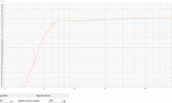
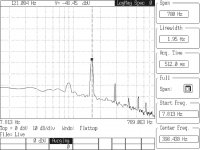
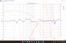
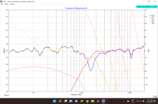
4. Low extension F3 60Hz
Current F3 = 60Hz , F10 = 47Hz (winISD)

5. Simulation peak SPL to hit 116dB at peak, 110dB 50Hz
Current max SPL = 118dB (winISD), 50Hz = 110dB

6. Power distribution must be 90 horizontal x 70+ vertical. More the merrier.
Constant directivity horn supports this

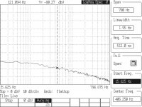
7. No enclosure modes or resonances
Current modal analysis moves all fundamentals 400Hz+

7. Battery is to last 4hrs at full pelt, 12hrs at 100dB (sim)
Estimated life at full = 5.5hrs, 100dB = 22hrs.

8. DSP on board w/ missing fundamental
Check


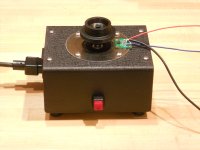
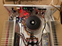
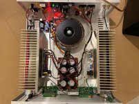
Here is the current plan for the build:
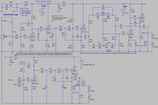
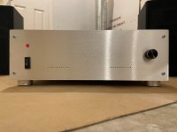
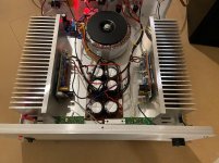
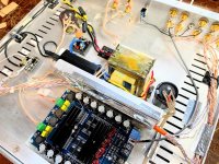
Electronics
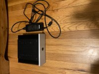
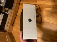
Power source: 36v 354Wh ebike battery (already owned)
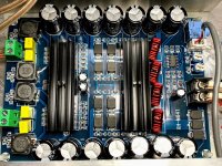
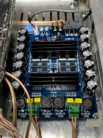
Amplifier: 3e TPA3255
DSP: Sure ADAU1701 (already owned)
Buck converter (option to bypass, only used if want to sacrifice battery for a couple of dB): 400w Chinese module (already owned)

Drivers
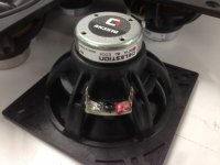
LF driver: 1x B&C 12CL64 (1.9kg! BL:17.5, qts: 0.3)
12CL64 LF Drivers - B&C Speakers
HF driver: 1x B&C DE111 (320g! 1.2kHz full power XO)
DE111 HF Drivers - B&C Speakers
Horn: 1x RCF H100 (800hz cutoff, 90x75, CD)
Product Detail - RCF
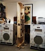
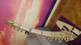
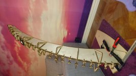
Enclosure
Material: Poplar plywood, 9mm
External dimensions: 65 x 35 x 25cm
Coating: PU laquer
Tuned: vent at 60Hz
Build methodology: Braced as per FEM and battened at edges (18mm glue area)


How do you all feel this is as a plan to hit the specifications? Is there any other creative approach you would consider? :wiz::wiz::wiz:

The LF section is of course the limiting factor for both battery life and SPL. I have looked at BP6 and tapped horn (such as cubo12) arrangements, but I am struggling to get any to work better in the 45L range. As per equal loudness and directivity, I expect around +12dB of gain to be added around 60Hz to keep it sounding 'full' outdoors

Otherwise, would you rather pair the LF with a 5/6" midrange driver (eg B&C MDN38) and tweeter (eg P-audio PHT-407N) with a passive XO? Do you feel the integration or intelligibility would be worth the extra cost and complexity?

Cheers,

Attachments

  • Screenshot 2021-01-15 at 16.22.08.png
    Screenshot 2021-01-15 at 16.22.08.png
    101.9 KB · Views: 600

Audio interface with 10 outputs

Hi everyone.
I have a project where I need to connect my laptop to 10 different guitar amps.
My idea is to buy an audio interface with 10+ outputs (I don't really care about inputs)

For example, I found those :
Behringer UMC1820 – Thomann UK (10x 6.3 mm jack line outputs (1 + 2 monitor output L/R))
Tascam Series 208i – Thomann UK (2 Balanced TRS main outputs with front level control + 6 Balanced TRS outputs + 2 Stereo headphone outputs)
ESI U108 PRE – Thomann UK (8 Balanced line outputs: 6.3 mm TRS + Stereo monitor outputs: 2x 6.3 mm jack + Headphone output: 6.3 mm jack)


My question is, with those kind of audio interfaces, can I send a different audio signal to each output channel? I guess(and hope) the answer is yes. But I really need to make sure about it before buying anything

Thanks in advance for your help!

Amp for a speaker

Hi all,
I got a speaker that i want to modify. I want to pop the battery and an amplifier in it. Please could anyone help me what amplifier could run this speaker? Preferably bluetooth 5.0 if possible and I think It should be mono as well. The speaker is Identical like the one on the picture and woofer is 4ohm 50zt-1, mid is 8ohm 20 vt-5. I dont know what vt and zt mean tho.

Acoustic Reference SM-1000 3 Way Speakers Black High End Very good condition | eBay

Preferably I would like to buy something local (UK) if possible rather than wait from aliexpress, but if I have to order from ali thats not an issue.

If anyone can help or has a suggestion please post it.
Any help in this matter is appreciated

Hurst Motors: 300 RPM vs 600 RPM--Upgrade or Myth?

It's a commonly held opinion that a Hurst 300 RPM motor is an upgrade to the stock 600 RPM motor used on a lot of tables. The reasons most commonly cited are:

1. Higher torque
2. Lower vibration due to finer cogging as a result of 24 poles vs 12 poles.

1. While it is true that a 300 RPM motor will have twice the torque of a 600 RPM motor of the same power rating, the 300 RPM motor will require a pulley twice the size of a 600 RPM motor and have 1/2 the mechanical advantage, so the force (and therefore usable power) delivered to the platter, will be the same, assuming the same power rating in the motors. The downside of using the 300 RPM motor is the speed mismatch at power up between the pulley and platter will be greater than with a 600 RPM motor, so the "burn out" on the belt will be worse. It is analogous to trying to start a car moving from a dead stop by starting in 2nd gear (300 RPM) vs 1st gear (600 RPM).

2. Cogging is caused by the strong attraction between the permanent magnet rotor and the metal pole pieces and loss of attraction between the rotor and the air gaps between the poles as the rotor spins. The cogging feels "finer" in the 300 RPM motor when turned by hand because there are twice as many poles, but the motor spins at half the speed, so the frequency of the variable reluctance "cogs" will be the same: 5 revs/sec x 24 poles=120Hz for a 300 RPM motor and 10 revs/sec x 12 poles=120Hz for a 600 RPM motor.

Assuming the same strength of the PM rotors and the same clearance between rotor and poles, the strength of the cogging (and the amplitude of the vibrations) will be determined by the strength of the rotating field in the coils which is a function of the electrical power rating of the motor. A 300 RPM motor should have the same vibration signature as a 600 RPM motor of the same power rating.

I did some tests using an Analog Devices ADXL327 three axis accelerometer mounted directly to the ring on a VPI SAMA housing, using 3 Hurst motors: 5.5W 600 RPM, 7.5W 300 RPM and 10W 600 RPM . The tests were done with the motor firmly mounted in the housing, pulley installed (but no belt) and using the factory supplied (and recommended) phase cap. I even took care to place the SAMA at the same locaton on the bench which is 1½" maple butcher block. The ADXL327 is powered by 2 Lithium Ion batteries.

The first image below is the baseline reading: ADXL327 powered up and mounted on the motor housing with the motor off.

The second image is with a 5.5W 600 RPM motor with 0.5uFd phase cap. The primary response is at 120Hz as expected and the level of vibration is -52dB or 28 dB higher than baseline.

The third image is with a 7.5W 300 RPM motor with 0.68uFd phase cap. The primary response is also at 120Hz and the level of vibration is -48dB or 32dB higher than baseline and 4dB higher than the 600 RPM 5.5W motor.

The fourth image is with a 10W 600 RPM motor and 0.82uFd phase cap. The primary response is 120Hz at -43dB, 37dB higher than baseline and 5dB higher than the 7.5W motor.

The last image is a 12W 600 RPM BLDC motor driven by a 3 phase sinewave supply at 20Hz. The response at 60Hz was there with the supply on and off so I assume it is being induced into the wiring. The primary vibration from cogging would be at 10 revs/sec x 4 poles=40Hz and appears to be the same level as the baseline reading.

I don't have a dual motor assembly to test, but if the trend follows, the two 7.5W 300 RPM motors (15W) should have more vibration than the 10W 600 RPM motor. It is difficult to see why people consider the 300 RPM motors an upgrade from the 5.5W 600 RPM stock motor. The downside is the 300 RPM motors have higher vibration (as they are higher power) and cause more burn out on the belt. I don't see an upside.

Attachments

  • Baseline.jpg
    Baseline.jpg
    450.6 KB · Views: 1,020
  • Hurst 5.5W 600 RPM.jpg
    Hurst 5.5W 600 RPM.jpg
    413.6 KB · Views: 968
  • Hurst 7.5W 300 RPM.jpg
    Hurst 7.5W 300 RPM.jpg
    429.7 KB · Views: 947
  • Hurst 10W 600 RPM.jpg
    Hurst 10W 600 RPM.jpg
    427.5 KB · Views: 922
  • BLWS.jpg
    BLWS.jpg
    479.2 KB · Views: 937
  • DSCN1402.JPG
    DSCN1402.JPG
    250 KB · Views: 372
  • DSCN1403.JPG
    DSCN1403.JPG
    254.3 KB · Views: 370

Speaker level passive "2.1" crossover?

Hi all,

I make small funky speakers using eBay chip amps, and have really been enjoying it! There's a 50w/50w amp board with a single volume knob and bluetooth that Ive used a lot - mainly because it will go from 5v to 24v so can be powered from a variety of sources.

However, I find myself wanting to add a single mono sub to my designs but its not easy to see just HOW i can do this without things getting much more complicated. I know there are 2.1 amp boards out there (and for not much more money that the one I use) but they don't work down to 5v, which I really want.

So, how can I make a 2.1 crossover? I always thought such a thing MUST exist as I had a passive sub back in the day that had stereo inputs and stereo outputs, but I can't find such a thing "ready made" for the life of me.

Any ideas for a circuit?

Regards,
Jim

Restoring Bruel & Kjaer 1023 Sine Generator = Help!

Hello,
This is my all time favorite sine generator. In fact, it is not doing this equipment justice, just to call it sine generator. For example, the compressor (feedback) function is super handy if you want to compensate the irregularities in the driving transducer and measure the frequency response of an -say- accelerometer.

Anyways, it was in total dark, cold, non-working state when I received it. Fixed the power supply to generate the needed voltages without any ripples and discovered that, it is working in a narrower frequency band than the usual 20Hz to 20kHz. The sweep cuts early in the low frequency direction (nothing below 80Hz) and at high frequency region, there is nothing above 15kHz. The digital display goes dark at both directions and it cuts out the output. In between frequencies, everything works perfect. Frequency is spot on, output voltage is exact.

The only service manual which is on the web has the signal generation schematic blurred, I can not make out anything from the values or component IDs. Also, there is a mechanical switch that stops the generator when the dial is turned outside the scale limits. I have checked that and there is nothing wrong with its' operation.

Any idea, on where to start troubleshooting this problem, would be very much appreciated. Needless to say, I have already replaced the electrolytic and tantalum capacitors.

Thanks in advance,
Dirk

Headphone dummy load capacitance and inductance

Hi all,

I'm busy putting together a dummy load for testing headphone amplifiers. The necessary resistor values are straightforward enough, but I'd like to add some reactive loads that the headphones themselves as well as their cabling would present.

For capacitance, I'm thinking selectable 100pF, 220pF, 470pF, 1nF , 2.2nF and 4.7nF should cover things. Any thoughts here?

Inductance I'm less sure of - what sort of values would headphones likely possess?

Apple is Improving Phase Plugs and Coentrant Horns

It looks like Apple Computer has embraced:

1) horns

2) coentrant horns

3) phase plugs

Here's the patent they filed about seven months ago:

US10728652B2 - Adaptive array speaker
- Google Patents


This is a looooooooong patent.

From what I can see, the most obvious improvements are that the seven mid/hi drivers have a more sophisticated phase plug than the previous design.

From the looks of the BEM sims in the patent, it looks like Apple is trying to create a ring-shaped wavefront at the exit of the horn at the base of the Homepod. The idea is to basically have the Homepod behave like a ribbon tweeter, except it's a ring-shaped ribbon tweeter. Of course, the advantage here is that you can have the speaker play omnidirectionally, but you can also 'aim' the sound.

bang-olufsen-beolab-90-tweeters.jpg


Bang & Olufsen got here first, in 2006. I met Geoff Martin when he demo'd these for the first time. (Had to sneak in to the demo, I am a scofflaw!)

Lexicon-SL-1-ac.jpg


A year later, Harman showed off Horbach's SL-1

Apple is also using asymmetric pathlengths. IMHO, this may be a tip of the hat to Alexander Voishvillo over at Samsung/JBL/Harman. They're using asymmetry all over the place these days. I'm guessing they're doing this to reduce resonant peaks in their phase plugs and waveguides, as symmetry often contributes to resonant peaks and dips. (Same reason the Danley tapped horns are smoother than a conventional FLH of the same size.)

Some JBL designs:

811313d1579899155-square-pegs-mmp6xcd-jpg


811315d1579899155-square-pegs-2020-01-24-12_48_51-jbl-vtx-a12-nowy-3-dro-ny-koncertowy-system-liniowy-portalnaglosnie-png


Cool stuff. Who would have ever expected Apple Computer to be selling horn loudspeakers?

Attachments

  • 2021-01-23 15_47_37-US10728652B2 - Adaptive array speaker - Google Patents.png
    2021-01-23 15_47_37-US10728652B2 - Adaptive array speaker - Google Patents.png
    361.8 KB · Views: 389
  • 2021-01-23 15_40_17-US10728652B2 - Adaptive array speaker - Google Patents.png
    2021-01-23 15_40_17-US10728652B2 - Adaptive array speaker - Google Patents.png
    351.1 KB · Views: 206
  • HomePod-teardown-iFixit-009-768x549.jpg
    HomePod-teardown-iFixit-009-768x549.jpg
    27.6 KB · Views: 199
  • HomePod-teardown-iFixit-010.jpg
    HomePod-teardown-iFixit-010.jpg
    178.4 KB · Views: 173
  • Like
Reactions: MFJG

Can versus electrolytic capacitors

Got a 1971 Peavey series 300 bass amp that has 2 4200 MFD 50 vdc can capacitors. The ends are bulging so thought I should replace them. Local electronics store suggested electrolytic caps with same capacitance and voltage but the fuse blew when I connected them. Is there a difference between a can cap and an electrolytic (besides size). Thanks.

Basic question re: empty spot on input/output selector

I'm putting together a single-ended and balanced selector switch (it's basically two separate switches in one chassis). There are five possible outputs however only four are being used and there is no mechanical method of reducing the possible positions in these selectors. Should I be placing a 10K ohm or so resistor across ground and signal on the unbalanced side, and anything on the balanced side so there is some dummy input impedance? ...or should they just be left empty.

Thanks very much for any suggestions!

  • Locked
Dynamic transcoding and convolution in Logitechmediaserver

YCLD - Dynamic transcoding and convolution in Logitechmediaserver

I'v always liked the idea to have the option to transcode AND apply convolution in LMS without many headaches. ATM there is C-3PO as a plugin for transcoding (but not optimal for convolution) and the hacked squeezelite SuperPlayer (I love it but it breaks the client-server paradigm where all the load should be on the server).

So I decided to make my own wrapping all the SoX + CamillaDSP logic.
I based it on a previous software which I made for batch audio file conversion (Recursive Audio Converter GUI) and I basically add to it the option to read and write from/to pipes and to read wav headers .

It is ugly, it is in beta and it has bugs.

Installation
Download and untar (Link at the end of the post)
Make sure to have OpenJDK >= 11 installed

Usage
Bad news! Fot the moment you'll have to edit your custom-convert.conf file. I know it is a pain in the *** and I'll try to help anyone but even for me this lms file is dark magic. Later I'll made a GUI (Desktop/web/mobile or whatever).
Before anyone asks me : no, I won't write an official LMS plugin, I'll start writing PERL code in my life only for at least double the hourly wage I take now as a dev. (what an ugly language)

First Example:
Code:
flc flc * *
	# IFT:{START=--skip=%t}U:{END=--until=%v}
	[flac] -dcs $START$ $END$ -- $FILE$ | /usr/bin/java -jar /usr/local/bin/YCLD.jar --debug --input-dir stdin --output-dir stdout --output-bit 24 --output-rate NextSync --output-format flac --convolution /mnt/music/0000-EQ-FILES/LCD2
Explanation:
For whatever input flac file (also from Tidal or Qobuz), upsample it at double its current sample rate (ex 44100->88200) and then search in the convolution folder for an impulse named impulse{target_sample_rate}.bin/dbl/txt. In this case with a 44.1 input it will pick /mnt/music/0000-EQ-FILES/LCD2/impulse88200.dbl

Second example:
Code:
flc dsf * *
	# IFT:{START=--skip=%t}U:{END=--until=%v}
	[flac] -dcs $START$ $END$ -- $FILE$ | /usr/bin/java -jar /usr/local/bin/YCLD.jar --debug --input-dir stdin --output-dir stdout --output-bit 1 --output-rate 5644800 --output-format dsf --convolution /mnt/music/0000-EQ-FILES/LCD2
Explanation:
It will take the input file, apply convolution (with pcm->dsd the impulse MUST be at 352.8kHz) and then convert to DSD128

The possibilities are quite infinite, you can even do DSD64 -> convolution -> DSD256 (internally it will do DSD64->64/352k->HF fir filter->your custom fir filter->DSD256)

Config
In the tar.gz you'll find the main jar and config/config.properties

Example with comment:
Code:
[COLOR="SeaGreen"]#useless option in this case, useful when used as a batch converter. Dont' write 0 please, any value >= 1 is ok and won't make any difference[/COLOR]
Threads=12
[COLOR="SeaGreen"]#SoX path[/COLOR] 
SoXDir=/usr/local/bin/sox
[COLOR="SeaGreen"]#CamillaDSP path[/COLOR]
CamillaDSPDir=/usr/local/bin/camilladsp   
[COLOR="SeaGreen"]#where to write the debug file when --debug option is active[/COLOR]
DebugFile=/usr/local/bin/debug.log 
[COLOR="SeaGreen"]#Pre gain before apply convolution[/COLOR]   
PreProcessGain=-2  
[COLOR="SeaGreen"]#Useful only for batch conversion, keep it at 0 with LMS[/COLOR] 
Normalize=0
[COLOR="SeaGreen"]#when false you must pick a single impulse to apply, the sample rate of the filter MUST match the output sample rate. When true you can instead specify a directory where multiple convolution files with different sample rates to be applied. The impulses MUST be named with the following syntax "impulse"<samplerate>.<extension> . Example: impulse44100.txt, impulse192000.dbl. When you convert TO DSD the sample rate of the impulse must be 352.8 kHz.[/COLOR]
UseMultipleConvolutionFiles=true
[COLOR="SeaGreen"]#check CamillaDSP wiki, FLOAT64LE = *.dbl, FLOAT32LE = *.bin, TEXT = *.txt[/COLOR]
ConvolutionFileFormat=FLOAT64LE
[COLOR="SeaGreen"]#compression level when output to flac[/COLOR]
CompressionLevel=8
[COLOR="SeaGreen"]Maximum PCM sample rate supported by your dac[/COLOR]
MaxSampleRate=384000
[COLOR="SeaGreen"]Maximum DSD sampel rate supported by your dac[/COLOR]
MaxDSDSampleRate=DSD128

Currently tested on Debian and FreeBSD. It should work on Win. Don't know about MacOS.

Downloads
YCLD download -> YCLD

Pre-compiled sox binaries with dsd support -> SoX

Pre-compiled CamillaDSP binaries (only with options needed by YCLD)-> CamillaDSP

If downloading from unix* command line --> curl -A "audiodigitale" -o /path/YCLD.tar.gz https://etc.etc.etc

Don't thank me, thank CamillaDSP and SoX devs and maintainers, and offer them a coffee.

Why YCLD ?
Easy! YourCpuLooksDelicious! Try to run it with both convolution and DSD upsample enabled and you'll understand

Question about Tektronix 120-086 transformer

Tektronix 120-086 transformer
Hello guys,
i'm not sure if tube section is the right place to start the thread about a Tektronix transformer i just bought for 40,00 €

Pic or it didn't happen ,right ?

The Tek part num. is 120-086 , the guy who sold me the thing told me it was salvaged from a 541 o-scope and service manual show that is true.

So i have all the voltages from the servie manual but no current ratings, except heater windings.

I could use the voltage drop on the series 10 ohm resistors stated on the service manual, but i think this monster is capable of more than this. Dimension and weight tell me this Iron is around 500VA and more...


Anyone can give me advices ?

Also would you rather use it for a tube amp or to make a bench supply ?

Luxman uses ROHM Semiconductor MUS-IC BD34301EKV dac

Luxman's 22.4kg, ~$17,000, D-10x SACD/CD player uses ROHM Semiconductor MUS-IC BD34301EKV . A 768kHz sampling, 32bit ⊿Σ Stereo Audio D/A Converter.
ROHM Musical Device: MUS-IC

pb2.jpg


This may be their first step into high-end audio dacs, tho' the Japanese company has been around since 1958. Rohm - Wikipedia

No price or datasheet info seems to avail, but a shorty summary pages is on Mouser.
BD34301EKV High-Performance Audio-DAC - ROHM | Mouser

Different hfe on output transistors

Hello,

They gave me an amp from the late 70s and it is an Inkel AK-650. The device is very cool but at the having been in a carpentry shop for 10 years I have had to clean it thoroughly. The fact is that going through the circuit of the amplifier stage there are burned resistors (nothing serious) and the output transistors of a channel are also kaput. They are a Bjt B557 pnp and its complementary D427npn, totally discontinued. In the channel that works, I have made some measurements on the disassembled output transistors that work well:

B557 hfe 45 D427 hfe 51 * Are matched *
Vbe 573mv Vbe 570mv
Ic 6.1mA Ic 6.2mA

By equivalence I will use the MJ221193G pnp transistors and their complementary MJ21194G npn:

MJ21193G hfe 78 MJ21194G hfe 62
Vbe 556mv Vbe 554mv
Ic 6.2mA Ic 6.2 mA

The difference in hfe in this last couple is clear and my doubt is that if this difference in gain could cause any oscillation or malfunction.

Thanks in advance and greetings
Projects by fanatics, for fanatics
Get answers and advice for everyone wanting to learn the art of audio.
Join the Community
507,772
Members
7,887,917
Messages

Filter

Forum Statistics

Threads
406,206
Messages
7,887,917
Members
507,772
Latest member
Hypertone