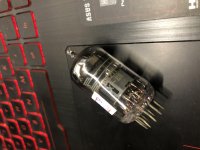
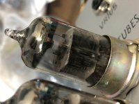
Sharing time. I recently finished the build of my third OTL headphone amp. First one had a SS output with tube input, second was a SRPP+ build. Latest is an ECC99 White cathode follower output with a 12AT7 as input tube. It's loosly based on the 'Morgan Jones' headphone amp, with lots of tweaked resistor values, alterations to accommodate the ECC99's and some other things. The WCF is partly LED, partly resistor biased as a compromise between distortion, dissipation and output. HT and the input tube's heater are regulated, the ECC99 heater's are AC, mainly to the current demand.
Some measured figures. All into 47 ohms resistive load @ 1kHz (if applicable):
THD: 0.017%
THD+N: 0.96% (needs work)
Output impedance: 5.6 ohm
Freq response @ 20Hz: -0.065dB
Oh yeah, and it sounds awesome!
It's still a 'prototype' so no enclosure will be build. So I had to find something that was cheap, available and easy to work with. LEGO! I still have loads lying around, it's an electrical insulator, and can stand some heat. Perfect. I felt like a child again, sore knees and all
The pic with the open enclosure is (obviously) with temporary output caps.

.jpg")
Some measured figures. All into 47 ohms resistive load @ 1kHz (if applicable):
THD: 0.017%
THD+N: 0.96% (needs work)
Output impedance: 5.6 ohm
Freq response @ 20Hz: -0.065dB
Oh yeah, and it sounds awesome!
It's still a 'prototype' so no enclosure will be build. So I had to find something that was cheap, available and easy to work with. LEGO! I still have loads lying around, it's an electrical insulator, and can stand some heat. Perfect. I felt like a child again, sore knees and all
The pic with the open enclosure is (obviously) with temporary output caps.
Last edited:

Hi Ian,
Good point! I forgot to mention the levels. The THD and THD+N were measured at 1Khz with 300 mVpp output, into a 47 ohm resistive load. At 1Vpp output, the THD rises to about 0.1%, but than the SPL in my AKG 271 is deafening. THD+N decreases to around 0.6%/0.7% with the higher output.
I measured the output impedance with the load /no load method. I used a 1kHz signal again into a 47 resistive load and measured the two different waveforms on my scope. Zout = ((Vnoload - Vload) / Vload) * Rload. And it agrees with the LTSpice simulation.
Edit: One thing I forgot (it was late, long day and all that), was the current absence of the input caps. Low end frequency will be reduced slightly when they're fitted (still in the mail). That way, I'll let the input polyprops set the frequency response instead of the output electrolytics.
Last edited:
Hi Ian,
Good point! I forgot to mention the levels. The THD and THD+N were measured at 1Khz with 300 mVpp output, into a 47 ohm resistive load. At 1Vpp output, the THD rises to about 0.1%, but than the SPL in my AKG 271 is deafening. THD+N decreases to around 0.6%/0.7% with the higher output.
I measured the output impedance with the load /no load method. I used a 1kHz signal again into a 47 resistive load and measured the two different waveforms on my scope. Zout = ((Vnoload - Vload) / Vload) * Rload. And it agrees with the LTSpice simulation.
Edit: One thing I forgot (it was late, long day and all that), was the current absence of the input caps. Low end frequency will be reduced slightly when they're fitted (still in the mail). That way, I'll let the input polyprops set the frequency response instead of the output electrolytics.
Excellent. That mkes sense. The THD+Nmeasurements are puzzling though. Do you think there is a noise problem? Perhaps the cathode LED?
Cheers
Ian
Excellent. That mkes sense. The THD+Nmeasurements are puzzling though. Do you think there is a noise problem? Perhaps the cathode LED?
Cheers
Ian
Yes, the THD+N needs some work. There's a fairly large 50Hz component in there which accounts for most of the noise, so I don't suspect the LED's at this time for the rather high value. Higher frequency noise is at immeasurable (for me) levels. So I'll have to find out where it's coming from. The transformer (toroid) is all the way in the back, as is any mains wiring or on-off switch, so EMI seems unlikely. I do have some ideas concerning grounding but any suggestions are welcome off course.
Yes, the THD+N needs some work. There's a fairly large 50Hz component in there which accounts for most of the noise, so I don't suspect the LED's at this time for the rather high value. Higher frequency noise is at immeasurable (for me) levels. So I'll have to find out where it's coming from. The transformer (toroid) is all the way in the back, as is any mains wiring or on-off switch, so EMI seems unlikely. I do have some ideas concerning grounding but any suggestions are welcome off course.
Ah, good old hum. The first thing to check is that the heaters are connected to 0V at some point. Do you have elevated heaters? With topologies like the White follower, the top triode's cathode is way above ground. This can mean its Vhk is exceeded. The usual way to fix this is to raise the heaters to 75V or so above ground. My ECC99 SRPP based headphones amp runs on ac heaters without hum so there should be no need to use dc heaters.
I am not sure what the PSRR of the White follower is but there is a fairly easy path for HT noise from the top resistor straight to the grid of the bottom triode so maybe the HT needs to be particularly clean.
By the way, what plate current is the ECC99 running at?
Cheers
Ian


Using a 12ax7 in the first stage (and dropping the plate current to say .5-1ma) will give you more open loop gain which will help with the THD. So will bypassing the cathode resistor on the first stage. Making the top 220R on the ECC99 to 330R may also null out the second harmonic. Glad it works well. Like the LEGO.
Last edited:
Using a 12ax7 in the first stage (and dropping the plate current to say .5-1ma) will give you more open loop gain which will help with the THD. So will bypassing the cathode resistor on the first stage. Making the top 220R on the ECC99 to 330R may also null out the second harmonic. Glad it works well. Like the LEGO.
Thanks for the suggestion!
I ended up with using Soviet 6N2P in the first stage which is quite similar to 12AX7 but with 6.3v filament voltage.
It has a NFB loop which sets the gain to 100k/10k = 10. I don't know if I can increase gain by bypassing cathode without changing value of NFB. Could someone explain how this works?
Attachments
Last edited:
The NFB gain is = 100K / (10K | VR) so it will vary with volume. VR is the parallel combined impedance of the pot to ground and the pot through the input signal path. U
sually a gain of 3x is good for headphone amps. Normally you would make R1 say twice the pot value so this effect is minimized. The closed loop gain will approach the ratio of the resistors when the open loop gain is large. Increasing open loop gain may affect stability but this is not normally a problem for a simple dominate pole which is what you have. NFB will only help if the output stage has enough drive at the output string not clip.
sually a gain of 3x is good for headphone amps. Normally you would make R1 say twice the pot value so this effect is minimized. The closed loop gain will approach the ratio of the resistors when the open loop gain is large. Increasing open loop gain may affect stability but this is not normally a problem for a simple dominate pole which is what you have. NFB will only help if the output stage has enough drive at the output string not clip.
Making the top 220R on the ECC99 to 330R may also null out the second harmonic.
Would R5 need attention given the change would shift the tube's alignment downward by a couple of volts?
R5 is just there to make sure there is a DC path to ground to the grid operates at 0V. Its value is non critical. If the first stage valve has been changed the bias point there may no longer be optimal.
True. I was thinking that lowering the R5 value means the 12AX7 sees a lower value too.
Wow, seven years have past since my initial post of this amp. Time flies!
If I were to rebuild this schematic, I would change a couple of things to be honest. Might be fun to do in the winter season, so here are some of my thoughts.
- I'd use a 12AX7 instead of the 12AT7. More gain and no need for the extra transconductance.
- The amount of feedback would be revisited and with that, the stability and frequency characteristics.
- The 12AX7 would have a constant current sink at its cathode for even more gain that will benefit the amount of feedback.
- I would experiment with a PNP transistor as the lower element of the cathode follower. It wouldn't be a white cathode follower anymore, but it will function similarly and massively outperform a regular cathode follower! This way I could drop one full ECC99, saving space and halving heater current. A DC heater would become practical, reducing 50Hz components in the audio output.
- I would experiment more with the output capacitor. I've since then never had to use these amount of farads on an output, so never had to, but I would take a deep dive in the distortion characteristics of the electrolytics. Would bypassing with a foil cap in this case change anything for example? Different brands? Setting the -3dB point even further from audible frequencies?
Aiding the tubes with silicon might steer it away from a 'true tube' amplifier, but it think it would be a nice build.
Nice build man, I like it!Thanks for sharing the schematic and I built one and it was good!
The 12AX7 is DC coupled to the cathode follower stage, so it only 'sees' the grid of the ECC99 and not R5 for example.True. I was thinking that lowering the R5 value means the 12AX7 sees a lower value too.
If I were to rebuild this schematic, I would change a couple of things to be honest. Might be fun to do in the winter season, so here are some of my thoughts.
- I'd use a 12AX7 instead of the 12AT7. More gain and no need for the extra transconductance.
- The amount of feedback would be revisited and with that, the stability and frequency characteristics.
- The 12AX7 would have a constant current sink at its cathode for even more gain that will benefit the amount of feedback.
- I would experiment with a PNP transistor as the lower element of the cathode follower. It wouldn't be a white cathode follower anymore, but it will function similarly and massively outperform a regular cathode follower! This way I could drop one full ECC99, saving space and halving heater current. A DC heater would become practical, reducing 50Hz components in the audio output.
- I would experiment more with the output capacitor. I've since then never had to use these amount of farads on an output, so never had to, but I would take a deep dive in the distortion characteristics of the electrolytics. Would bypassing with a foil cap in this case change anything for example? Different brands? Setting the -3dB point even further from audible frequencies?
Aiding the tubes with silicon might steer it away from a 'true tube' amplifier, but it think it would be a nice build.
Last edited:
The 12AX7 is DC coupled to the cathode follower stage, so it only 'sees' the grid of the ECC99 and not R5 for example.
Good point - I need my eyes (and brain) tested.
- Home
- Amplifiers
- Tubes / Valves
- OTL WCF headphone amp build + awesome prototype material