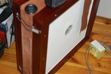
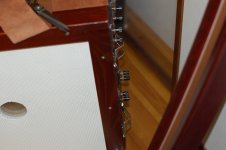
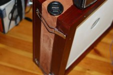
A DIY MEMS Measurement Microphone

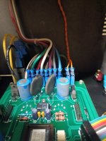
FULL pic.jpg

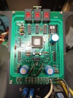
Mic InLine.png
Program Manager: “Engineers never think the design is finished”.
(The Program Manager thinks all is done if the prototype isn’t in flames)

Hello, DIYers!

This is intended to be a series of posts about several trial batches of DIY measurement microphones that I built. I was playing with the design as a possible product for Dayton Audio. No decision was made yet on whether Dayton will actually pursue this, but they are ok with me writing about how these could be made (by some more skilled DIY constructors).

It will be partly a how-to, partly a technical design discussion, and partly a documentation about obsessive engineering behavior.

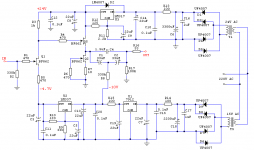
The microphone is an ultra-slim, small acoustic profile, wideband device with very flat response even without an individual correction file. A short cord connects the mic wand to its electronics board that provides power (9V battery or 48V Phantom), as well as response flattening circuitry and drive for balanced XLR and RCA outputs. The design capitalizes on the repeatability of MEMS chips’ sensitivity and frequency response.

-------
ERRATA:

  • some later posts mention using 38AWG enameled wires for wiring the chip. That should be 36AWG. AWG38 would of course work electrically, but won't have much of any stiffness and so is difficult to handle even with tweezers to position onto the pads and tack-solder. A little stiffness helps a lot. Even 34AWG would probably be ok, but 36 was easier to find. For example, TheElectricGodmine.com item #G27281
    https://theelectronicgoldmine.com/p...jlFgBwuZ5ccgkjYya1pgI-1UYeRFbfSuqFWYDJH3ljWOi

[index into relevant later design posts:]
  1. Frequency Response curves for mics without adjustment
  2. Arguments Pro and Con
  3. 3D Printed Mounting adaptor for MEMS chip
  4. Equalization Method
  5. Performance Specs
  6. Assembly Fixture
  7. Bypassing and Ground wire
  8. Assembly of the Microphone Wand
  9. Skill Level needed
  10. How Calibration was Done on test run mics
  11. Equalizer/Interface Box and related 3D printed parts
  12. Files download package

STL, GERBER, Lists, schematic, notes are now available 9/13/2024

Hello from Denmark

Recently retired, I now have more time to fiddle with my home theatre equipment, which has been dormant for quite some time.

Current gear:
Marantz SR6011 9.1 channel receiver,
Rauna Leira II, Front speakers
Jamo Concert Center speaker
Home build (Seas based) surround speakers
Home build sub (from now retired magazine "high fidelity") with (unknown) Peerless 15".

Mitsubishi DA-F20 tuner outputs levels

Greetings,

I recently picked up a sweet F20 and I'm wondering why Mitu would of decided on such a low (150mv/5k) output on the fixed outputs. I just installed it and listened to it for a week or so. And thought gee something must be off as the presentation was not well balanced. Like a fat bottom with murky mids and dampened highs. So I looked up the specs and was shocked to find such a low level. So I switched to the variable out(500mv/5k) and that completely changed thing for the better as the cloud has more or less lifted. Nevertheless both seem to be a bit low as I see 1000mv is more of the usual norm with many designs.

Which has me wondering if I shouldn't consider possibly altering the output stage to raise it. Plus I'm debating replacing the final 4.7uf coupling cap to a film type to see if that cleans things up a bit. Of perhaps I should just leave it stock.

Any thoughts would be greatly appreciated.

DD

Technics SU-V9 Startup Issues

Hello diy audio community. I currently have a Technics SU-V9 on my bench that I'm attempting to repair. I know my way around tube amps well enough, but my knowledge of anything transistor-based is sorely lacking, so I've come here seeking advice.

I believe the main problem with this amp is related to the protective circuitry which engages the main DC voltage rails. The amp powers up and doesn't blow the fuse, but neither of the internal relays click on.

I'll attach the service manual which has the schematic for reference… There are two transistors (Q601 and Q606) which I believe activate the thyristors for the DC + and - rails (D601 - D604), but I don't think they are turning on - Q601 collector and Q606 emitter both read 0V when they should be +16 and -14, respectively. Tracing things backward, Q603 and Q605 don't appear to be conducting, either. Neither does Q505, which seems to be what drives Q603 and Q605. Q505 has 0.1V on its emitter, when it should have 4.7V. Finally, some of the pins on IC501, the muting/relay drive circuit, don't show the correct voltage, but at least there's 3 volts on pin 9 (DC power to the chip itself).

And that's about as far as I've been able to get with it. Like I said, my knowledge of solid-state transistor logic is pretty weak...

Some other observations, which I'm not sure if they should be cause for alarm: the DC + and - rails after the thyristors read about +20 and -30 volts, and drift by +/- a few volts every couple seconds. There is also a very slight ticking sound coming from the power transformer, which is in sync with the fluctuations on those DC + and - lines.

The AC voltages from the power transformer secondary seem okay and are stable (I think around ~40V for one pair and ~50V for the other). And the DC + and - supplies prior to the thyristors also seem okay and stable, about +47V and -46V.

Phew, sorry for the long post. If you're still paying attention, any ideas what might be causing this behavior or what to chec
k next? TIA!

Attachments

Peppy player

Hi,

Almost one year ago I posted information about my audio player:
http://www.diyaudio.com/forums/pc-based/273684-another-raspberry-pi-radio.html
http://www.diyaudio.com/forums/construction-tips/273690-woodware.html
Since that time I redesigned the hardware and software components. Now it's based
on Raspberry Pi 2 and Amp+. The software part was changed completely. And now
the project has its name - 'Peppy Player'.

All the details about this project can be found here:
https://github.com/project-owner/Peppy.doc/wiki

And here is the summary:

This is DIY project which includes three components: hardware, software
and woodware. All three components were created for this project from scratch.

Here are the key features of the hardware component:
* It is based on the popular single-board computer Raspberry Pi 2.
* High quality audio achieved by using integrated Amplifier module HiFiBerry Amp+ and Sony speakers.
* The Hardware has six "senses" to control its functionality:
- Mouse
- Keyboard
- Touchscreen
- Infrared Remote Control
- Rotary Encoders
- Any computer in a local network or mobile device with Web Browser

Here are the key features of the Software component:
* This is application written in Python.
* Peppy provides Graphical User Interface for audio players running in a headless mode. Currently Peppy supports 'Mpd' audio player.
* Embedded Web Server allows to control audio playback from any Web Browser.
* The default touchscreen resolution is 480*320. This is the resolution of the TFT used for this project. Though UI is dynamic and can scale to any screen resolution.
* Currently Peppy has only Internet Radio functionality. In the future releases support for playing audio files and streams will be implemented as well.
* By default Peppy has playlists containing free radio stations for English, French, German and Russian languages. Users can add their own stations to the playlists.

The key features of the Woodware component include:
* Original custom design.
* Made of solid wood (Cherry and Walnut).
* Natural finish - the variation of French polish.

I hope that the information about this project will be useful for all
DIY developers as it brings together many different aspects of developing
hardware, software and woodware fro Raspberry Pi platform.

Enjoy!

Bad startup crackle

Sorry this isn't actually about a diy amp, but a triode labs. But this is probably the best forum to help me out.

My knowledge is fairly limited here. When I turn my amp on there is an intense "crackle" (the one thats kind of like radio static) that is actually causing major excursion on the driver - enough that I won't be turning it on again.

To me it sounds just like a tube that's gone out, I've heard this before, but I switched all tubes to the other channel and it's still in the same channel. That seems odd to me.

Could this be a bad transformer? Tune socket? Simple cable connection?

I'll have to bring another (cheap) speaker in to try any troubleshooting I guess, but any pointers would be appreciated.

Low cost reno / modernization of 1950's Zenith Console (Pictures of work so far)

This started as a project to simply replace the turntable... Then the amp was obviously shot and at that point the tuner was a lost cause to so it was gut and start over.

The mounting of new components is clunky for now as I work on finding someone to make me some actual mounting brackets etc.

I will post a few messages as a thread of sorts. Open to any additional suggestions or recommendations before I start wire management and buttoning it up.

Starting point:

1740529432429.png


The back off:

1740529574659.png


After a couple of removals:

1740529616918.png


1740529680856.png
  • Like
Reactions: Freedom666 and GM

Threshold 400A. L/R Channel out and fix

IMG_6352.jpeg


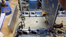
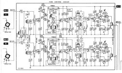
When i first opened for visual, no supply fuse., A toasted resistor divider which goes to lower 4 A6 pnp devices. Did a quick continuity check looking for CE shorts on A6s. Found 3 with BC shorts.
As show in pic, I proceeded to pull all 4 outputs. 3 were shorted as measured in circuit, the single survivor was limping along with ~ 2 mA collector leakage.Of Collector. All four will be replaced. Route cause is unknown as of now.
IMG_6347.jpeg
IMG_6335.jpeg


Pic of backside. Rated E for everyone.

IMG_6341.jpeg


Turned my attention to amp board. At first glance, I noticed the roached resistors. Both appear to be 1k ohm. 1-2W wirewound. I feel they are too closed to the board for my liking. I Will be replacing these with a higher wattage wire wound resistor and lifted further from board for better airflow. There are absolutely no markings on pcb. 🙄 A total of 18 transistors

10 x MPSA42’s——>MSP42’s
5 x MPSA92’s———>MSP92’s
2 x MPS6571’s—>ZTX694’s(1100 hfe)
1 x 2N4250—->KSC733C (ECB)

Note all are EBC orientation. I had to bend pins on 733C. Mind orientation.
Use schematic.

Diodes 1N4148x4 and 1N4007 x2

Dozen or so caps replaced. Go through all passives and verify values.

There're a few other pieces of silicon......... consisting of 6 diodes.

3 electrolytics and some film and tant capacitors.

5k bias trim pot. No trim for offset other than front end cascode diff pair and base mirror.

In this version CFE1078 a pair of moto 42/92’s is used as pre driver. Not as beefy as i would have expected.

This unit looks untouched so i suspect I'm looking at original components. Assuming this unit was used hard and has seen Venus type temperatures ….very impressed that it made it to year 2023.

The MPS6571 cascode devices and the 2n4250 concern me. I plan on testing each device. I suspect these have some high beta properties which may be difficult to match with modern replacements (IF NEEDED).

I’ll need to inspect the supporting circuits to see what else is damaged. I did notice the 47uF/50V is now open.


IMG_6363.jpeg
  • Like
Reactions: Mikerodrig27

Fast Sub-band Adaptive Filtering (FSAF)- an introduction

A long time ago, sound experts had to use their ears to do their job, which was hard. They wanted a better way to measure speakers and rooms. They could have used advanced math, but they didn't have the powerful computers that were needed back then (and still don't exist today).

In 1985, the iNTEL 80386 CPU just had just been released. Doug Rife founded DRA Labs in 1986, and released MLSSA in 1987. It was software AND hardware to go hand in hand for the PC. It came with sound card with a 12bit ADC that fit into the computer's ISA slot, and was capable of sampling in excess of 100KHz.
(IBM and compatible PCs didn't have ADCs at that time)

Around the same time a company called Audiomatica in Italy releases Clio, which it's own HR-2000 hardware that plugged into a PC's ISA slot + software to run in DOS.

These hardware/software solutions needed a 32bit PC, as well as also an optional math co-processor 80387, which costed US $800 in 1987)… $2000 in today’s money) just for MLSSA to run.

At this time computer were at their infancy, but anyone doing any real work had to opt for that math co-processor. When the 80486 CPU came in 1989, it had a built-in math co-processor, and a complete PC with monitor, keyboard and costed around US$3,000 (US$7,500 in today's money). Sounds like a lot, but it seemed like a bargain compared to the original IBM PC which has meagre performance.

Moving forward, in 2000, Angelo Farina with his AES paper, discussed the logarithmic sine sweep, aka log chirp, borrowing from radar technology, created by Sidney Darlington in 1947. It was better than the previous method… yet still people said these measurements didn't match what they actually heard.

In the early 2000s, Michael Tsiroulnikov invented a "divide and conquer" method that allowed acousticians to use better math, without spending too much money or computing resources and named it FSAF.

What is FSAF?

"Fast Sub-band Adaptive Filtering (FSAF) is a technique used in audio processing to measure and separate the music from everything else. It is a proven technology that has been tested, and used in the real world in the field of acoustic echo cancellation.

Have you experienced this technology before? Good chances you probably have. Have you ever witnessed someone talking to a smart speaker to say e.g.

“Hey Google, what’s the time?” whilst the smart speaker was still playing music?
How was the microphone able to hear what was said, above all the loud music that was being played?

Here's how it works in the context of listening to, and testing audio devices, like speakers.


1. Splitting the Signal:
FSAF divides the audio signal into smaller frequency bands, called sub-bands. Think of it as dividing a picture into small pieces, like pieces of a jigsaw puzzle. Each sub-band contains a specific range of frequencies, making it easier to analyze.

2. Adaptive Filtering:
The technique uses adaptive filters that can adjust themselves in real-time to changes in the audio signal. This helps in accurately measuring each sub-band.

3. Measuring distortions
In each sub-band, changes in the signal can be treated as additive noise. By using a mathematical method called Least Squares, we can estimate the true response of the speaker and the room for that specific sub-band. This estimation gives us a clear picture of how the audio should sound without the added character, effects or noise from the speaker.

4. Combining Results: After analyzing each sub-band individually, the results are combined to create a full-band response. Think of it like putting all the puzzle pieces back together to see the complete picture. The added character, effects and noise calculated for each sub-band are actually discarded in this step.

5. Full-Band Distortion Measurement: The full-band response, which is now a more accurate representation of the speaker and room's true sound, is used to identify the character, effects and noise. These distortions are the leftover “residuals” after applying linear filtering.


Thus, FSAF allows one to play music through a DAC/ADC, an amplifier, or a speaker, and “subtract” the original input from it.

What you have left over is the “residual” - parts that weren’t in the original audio file.

So what can expect to hear with FSAF, when measuring your speakers?

For starters, yes you will get your frequency response.

You will also be able to listen to distortion. Harmonic distortion, intermodulation distortion… all audio that isn't the original file being played back. This includes noise, the Barkhousen effect, ringing, echoes… even faint sounds that you had been accustomed to and your brain may have tuned out e.g. cars driving by, the steady tick of the second hand of a distant wall mounted clock, it’s all there.

For a long time FSAF was used in industry in acoustic echo cancellation, but as of June 2024, it was incorporated in REW 5.40 beta32. It is still in beta testing...

ALPS Motor Potentiometer Remote Control Circuit

Hi,
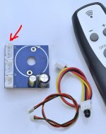
I have the ALPS27 Motor Potentiometer that I bought some time ago. I got it with a circuit for the remote conrol. But Ihave been looking all over to get a circuit diagram so that I can determine exactly what the J3 connector is used for. But I can not find anything. Any help with this is greatly appreciated.

Attachments

  • circuit.jpg
    circuit.jpg
    67.3 KB · Views: 158

DSL710A tray/transport

I've a DSL710 that has the usual no disk issue. It's been written that it's really a detector issue, but no matter. After opening the unit to my surprise I to found a HOP-1000 laser instead of a HOP1200s that I expected and had previously ordered. Can someone confirm or dismiss that the two lasers are interchangeable,? The player at present plays factory CDs but no CDR or DVDs. So most certainly it's the laser unit....
The best free program for modeling boxes for fullrange drivers and more?

Good afternoon everyone. I sold or gave away all of my programs but, bass box pro. Am looking to make a slot vented box for a pair of Mark Audio drivers I’m very fond of. The CHN-50s. I believe they are the best fullrange driver out there for the money hands down. So what program can I use to get the best results? Sorry if this has been asked before? Jeff

Cookies that should not be deleted when logging out

Whenever visiting DiyA, the first thing I do is scrolling to the bottom of the page to set the theme color and time/date format to my liking, but if I decide to log in and after a while log out, the theme color and time/date format cookies gets deleted at log out, would it be possible to exclude the following two cookies from being deleted at log out:
  • diyaudio_language_id
  • diyaudio_style_id
I have tried to use couple of cookie extensions in my browser and lock the cookies but it doesn't always work.
DiyA Style & Language (Date Time Style) Cookies.png


BTW, the placement of these theme color and time/date format settings at the bottom of the page and the behavior is rather annoying and frustrating when one have to reapply these setting several times a day, here's what the procedure look like right now:

  • Scroll all the way down to the bottom of the page (or use "End" button on the keyboard)
  • click on theme button
  • page represents the available styles in a pop-up window, but... AT THE TOP OF THE PAGE far from the bottom
  • ok, make a large mouse movement to the TOP OF THE PAGE to select the style...
  • page reloads and GOES BACK TO THE TOP, hey I am not done yet!!!
  • ok, one more round of this nonsense circus... scroll all the way down to the bottom of the page
  • ... click on the "YYYY-MM-DD / 12-hour clock" and select the one used in our region.
...rinse and repeat...........
  • page represents the available styles in a pop-up window, but... AT THE TOP OF THE PAGE far from the bottom
  • ok, make a large mouse movement to the TOP OF THE PAGE to select the style...
  • page reloads
Not fun.

please help with power supply for bass guitar combo amp

Hello all. David Seymour here. Long-time stalker, first-time poster. My current project is a bass guitar combo amp using this Sunn 200S preamp from EffectsLayouts.com coupled into this cheapo Chinese mono power amp stage. Meant to be small enough for solo practice and lugging around, but powerful enough for small ensemble gigs, maybe even with a modest drummer. Heatsink, cabinet design, and 8Ω speaker selection is done, but I need help figuring out the power supply. I'm definitely not a qualified electrical engineer. I'm handy with schematics and a solder station, but I know better than to mess around with power mains.

The Sunndering preamp is designed for DC 9V, presumably 500mA is plenty. The Chinese power amp PCB says it accepts wide power supply range, dual voltage DC +/- 20V-90V (not sure what that additional 12V input is on the bottom right.) I'm thinking 200W, 45V or 60V would be best, right? Trying to keep costs down; it's a bass guitar amp, after all, not a HIFI or audiophile grade application.

Is there such as thing as a ready-made solution for this? If not, can anyone point me to some existing DIY solutions, schematics, BOMs, etc? If not, who is able to design such a thing for cheap?

Thanks and cheers! 🍻

Preamp stage:
Sunndering.png


200W Power amp stage:
poweramp.png

Tapped-Kick-Horn

Hi guys! Are there any DIY tapped kick horn projects anywhere in the world? Or have such projects already been realized and I haven't found them? Or to put it another way: There are no TH kicks because it is perhaps impossible to construct a tapped horn as a kick horn? Or has no one tried to develop one yet? Questions, questions! I'm hoping for a little exchange of experience from the experts!

Best regards

Use volts measurement to determine max speaker volume?

I'm building a new system using a SEAS 4" Full Range and a SEAS 6" woofer. I'm trying to determine the point on my preamp volume control that represents enough power to blow the 4" driver (coil melt or cone damage) so that I don't get to or cross that boundary during listening sessions. 90% of the time I'm probably listening in the 65 to 85dB range, which I know isn't close to the power handling of the speaker. However, I'm sure we've all experienced a time or two when very loud is very good and inhibitions aren't properly in place. 🙄

The speaker has a 3.3ohm voice coil resistance. Handles 40W long term and 100W short term. If I use the equation of W = V-squared / ohms then it looks like somewhere around 11V amp output is the stopping point. I'm wondering if I can put my voltmeter on AC mode across the speaker terminals and figure out where the volume equals 11V and don't exceed that number on the preamp. (I also have an oscilloscope if that is a better tool to use.)

I'm asking in the Class D section because I'm using an ATI AT524NC amp that puts about 350W into 3.3 ohms at full tilt.

Balanced XLR output to unbalanced RCA question...

Hi. I don't mean to sound like a Gil Scott Heron song, but I'm new here, will ya show me around?

I'm tying to get the maximum level from a Source player that has both options of RCA's and XLR's outputs.
I would like to unbalance a balanced source, does that mean a straight short between pin 1 and 3 or ...

Decoupling capacitor between pin 1; Negative and pin 3; Gnd ? If so what type, material, size?

I'm used to studio gear and this Source player is a quasi balanced device, too sensitive for my likings.

O/C between 1 an 3 results in buzzzzzz

Hello all!

David Seymour here. Long time stalker, first time poster. I studied music production and audio engineering many years ago, am just getting back into it. I've designed or modified many stompbox circuits, mainly bass distortion, octave fuzz, reamping. Working on a few more primo balanced mic/instrument preamps. I'm a bass player, but no longer have a bass amp, so I'm currently building a combo amp from components designed by smarter people than myself. I need help with the power supply section, which I'll be posting about shortly.

Thanks and cheers everyone for generously sharing so much expertise!

Long time member but never posted

Hi all,

I guess I am posting this because it is a requirement to post.
🙂

Anyway, I never posted anything since my skill sets are still very novice and I never really had a question or challenge that I needed to seek an answer for. However, that is changing so I wlll be posting my question shortly that I hope someone can answer and lead me down the right path.

Dave

Rotary Encoder

I'm looking for recommendations for a quadrature rotary encoder with detents that has nice high-quality feel. Ideally, I'd like somewhere around 16-25 steps per revolution.

I've used the Bourns PEC11 series previously, and these work ok but feel kind of cheap.

Anyone have any experience with Nidec or Grayhill, or have other recommendations? I was looking at the Nidec REC20-25-201-1.

Thanks.

Hi from the French Alps!

Hi DiyAudio community !

I’m really happy to finally join this forum after countless hours of reading fascinating threads. This place has been incredibly helpful as a guest, and I can’t wait to get involved as a member!

I work as a fabricator in metal working field, in a small but cosy workshop. I mainly work around art work production and design for other artists. As well as this exciting job, I'm interested in diy practices and open design ideas.

Last year, I discovered the joy to have a listening room. After a lot of different vintage hifi setups, it was time to build my own !I’d love to share more about it in a dedicated thread.

✌️

Tubelab's collection of useful information related to DIY audio electronics

I started this thread to post the spreadsheet that I use to keep track of vacuum tubes that I have dealt with. I keep it updated as needed. I have posted older versions on diyAudio before, but they get lost in the crowd.

I have used this spreadsheet for years and have fixed several mistakes. I can't guarantee that there aren't any more. Use at your own risk, and consult a tube manual if in doubt.

I made this spreadsheet for my own use over a period of at least 20 years. It is not always consistent or complete since it was intended for my own use.

If there are any questions, requests, or comments feel free to post them, especially if you think that there is an error.

I'm sure that there are more goodies hidden in a dark corner of my 20 TB NAS drive box. I'll add them as found.

Attachments

Bass Reflex Port Construction

Hello,
I'm a novice at speaker enclosure design, so please forgive me if this is a dumb question. I'm designing an enclosure for a pair of small (3.5") full range speakers to use in a bedroom/office setting where high volume is not needed. I currently have the speakers in enclosures with a cylindrical port sized to achieve what seemed to be the lowest I could reasonably go without getting huge peaks and valleys in the transfer function curve using an app I found online.

While I like the sound of the current setup. I want to change some things to improve the overall setup and want to try to improve the bass output while I'm at it. Now, I'm looking to construct a multi-chambered enclosure with the full range drivers on each end of the front baffle and a 3" mini subwoofer in the center. To get the lowest bass output I can with a flat transfer function curve with the sub I'm considering, I need a very lengthy port that will take some creativity to build into my enclosure given the size limitations I have placed on it. I'm looking at using a labyrinth port design to achieve this.

After running different port scenarios in my app (single port, multiple ports all of different sizes, lengths, round and rectangular), I've concluded that a single port out of the speaker chamber gives me what I think is the best, flat response until it hits a steep drop off at the low frequency end. The geometry constraints of the overall cabinet makes it challenging to fit the labyrinth port in the box efficiently.

Finally to my question. Is it acceptable to have a single port out of the sub chamber, then Tee it a short ways downstream, then have two runs switch back and forth, terminating in two outlets? Can I count the length of port tubes on each side past the Tee toward the total length of port, or does the Tee somehow reduce the effectiveness of what comes after it.

Thanks for any advice you can give.

Rotel RA-611 Excess Hiss

Hi all,

My Rotel RA-611 produces excess hiss - enough that it's audible from across the room with the volume at zero. I believe the issue is in the Tone/Preamp section, since if I pull the connectors to the main amp the hiss is gone.

I've traced through the circuit with an audio probe and it's nice and quiet until the collectors of Q204 and Q208. From this point forward there is the loud hiss in the circuit. I thought it might be the 50 year old transistors, so replaced the 2SC644s with KSC1845Fs, which made no difference. All of the voltages match the schematic, the capacitors have been replaced and the carbon resistors have been replaced with metal film - also made no difference.

Please find the schematic attached.

Many thanks in advance for the help!

Attachments

  • Tone Control Circuit.jpg
    Tone Control Circuit.jpg
    533.8 KB · Views: 65

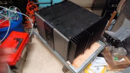
Krell FPB 200 Repair - stuck in protection mode

I found a dead Krell FPB 200 on sale for cheap. The seller wrote that it goes into protection immediately.
from past experience i knew, its gotta be a short somewhere in the output drive.

WhatsApp Bild 2025-01-29 um 12.39.47_50251aea.jpg
what too heavy and those handles at the back make no sense, it messes up the front frace when placing it down.
the fins are also quite pointy and sharp, you cant grab it there.


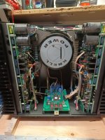
So i started taking it apart.
IMG_20250130_000241.jpg
Its well built, easy to take apart. a few screws here and there, and everything comes off in modules.

but its huge, its heavy. and its overbuilt as heck.
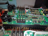
i mean what you need so many transistors to drive the output stage?

IMG_20250130_001204.jpg
IMG_20250130_001258.jpg

and its microprocessor controlled (biasing trough optocouplers that switch in and out resistors. it measured the rail and output voltage and currents at all time.

IMG_20250130_000247.jpg
IMG_20250130_001132.jpg

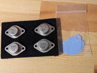
If its one of these, i might be screwed. Unobtanium TO-3's

IMG_20250130_001316.jpg

i didnt wanna do this to it, if possible:

WhatsApp Bild 2025-01-30 um 18.03.30_b37ba3b3.jpg


But after measuring several spots, i found no short.
so i kept digging, taking apart this PCB sandvich, comparing Left and Right for meter readings
and found a reading that wasnt equal on one so i looked whats hooked it to.
a shorted transistor, but after lifting the legs i noticed the short was still on the PCB

turned out to be a shorted silver Mica capacitor (1100pF)
firefox_qWmY8A3ZHq.png
after replacing it (all eight), it started working again!


for good measure i gave it a new set of electrolytics, the old ones where still good but the new ones are slightly lower esr and may last a while longer now.
WhatsApp Bild 2025-02-04 um 11.38.28_1c0a360e.jpg


After listening for a while.. i noticed this thing is a damn room heater.

60W in Standby!
180W when turned on..
1600W when theres a signal going in without even a load connected.. Class-A of course.

i listened a few hours and my room went to 35c.. nothing i want in my room 24/7.

it sounded good, nothing that immediately kicked me off my chair but alright for an class-a amp. may not have the right speakers for it.

i found my "jaboost" opamp-amp that ive built afterwards sounding slightly less fatiguing over long sessisons. and you dont want to leave the room afterwards.
https://www.diyaudio.com/community/...her-dont-expect-miracles.423889/#post-7929116


Its gonna find its place, someday, somewhere.

WD-5534 op-amp Driver 25 Watt T0-220

I have played around with similar simple circuits in the past for fun with numerous BJT Darlington Pairs as single package or discrete. Usually obtained around .0006 to .001%
1Watt THD1 using the classic 5534 as the driver. Typical expected 18 to 27 watts with op amps that you might tippy toe into the 22 volt area. ( Yeah Whatever more like 15 to 22 watts) to be safe.

A circuit design example was requested. So I made sure I was not blowing smoke up my own butt. Put together a more final circuit with hopefully real world stability margin.
Then run it up close to crest power and see what THD20 ( 20 kHz) was. Then post another sim amp that people love so much. Somebody might do a PCB ( probably not) and remind me diode thermal tracking makes everyone yell at the clouds. Until someone just has fun and is actually creative enough to build one. Woo Hoo

I like using diodes sometimes, because its fun and also easier with op amp drivers to use Boot Strap current source for the hardest swing you can get. Maybe live the Fantasy of getting 25 to 27 watts into a 4 ohm load. It actually does swing rather well driving a Darlington pair. The simple bias adjustment circuit will basically get you going dead centered at 50%. If you want to run 85 to 100ma for high frequency numbers about 55 to 65% will do it.

Yep T0-220 package for power transistor Using 80 volt 80 watt, 50 MHz fT with around max 1 amp current expected hfe should Hold 80 to 100 and yes minimum is rated 35 to 40 like a zillion other T0-220. D44VH10(NPN),D45VH10 (PNP) manufactured currently by On-Semi

WhiteDragonDesign5534_DARLINGTON_T0220_Amplifier.JPG


------------------------------------------------------------------------------------------------------------------------------------------------------------------------------------------------------

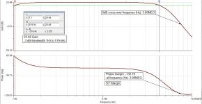
Bandwidth 1 Hz to 514 kHz stability phase margin 50° ( thumbnail click to enlarge)
WD-5534_Bandwidth_Phase_Margin.jpg

Clipping Behavior 4 ohm load ( thumbnail click to enlarge)
WD-5534_Clipping_4_Ohm.jpg

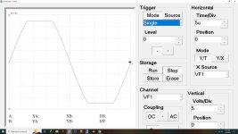
No Overshoot / Gain peaking 20 kHz 4 ohm load ( thumbnail click to enlarge)
WD-5534_Squarewave.jpg

THD1 ( 1 kHz) 2.83V output 1 Watt
WD_5534_THD1_1Watt_1000kHz.jpg
THD20 ( 20 kHz) 2.83V rms output 1 Watt
WD_5534_THD20_1Watt_20,000kHz.jpg

THD1 ( 1kHz) and THD20 ( 20kHz) with 300mV input and 900mV input 8 ohm and 4 ohm

8 ohm load
============================
300mV input 8 ohm Load 1.2 Watts output
============================
THD1 .0004 %
THD20 .003 %
============================
900mV input 8 ohm Load 11.2 Watts output
============================
THD1 .003 %
THD20 .007 %
-------------------------------------------------


4 ohm load
============================
300mV input 4 ohm Load 2.4 Watts output
============================
THD1 .0004 %
THD20 .006 %
=============================
900mV input 4 ohm Load 22.5 Watts output
=============================
THD1 .004 %
THD20 .01 %
-------------------------------------------------

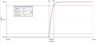
Slew Rate Measured 10 kHz 10 Volt Peak to Peak , 5 Volt Peak Delta X Delta Y 10% 90% 551 Nano Seconds
= 14.5V/us Slew Rate

WD-5534_SlewRate10kHz10vv.jpg

3 Way Line Array - dcx464 - mb12n405 - will it work?

Hello everyone. I got an idea looking at Peter Morris PM90 speaker if it could be used as line array cabinet with appropriate waveguide, then someone has offer "half" version of it with only one 12" and I really like it.
My idea is that single 12" design tilted to side.
Like a small line array high-end cabinet with fixed angles using coaxial dcx464 on "DOSC" waveguide crossed at 650Hz, together with mb12n405 on folded horn of PM90.
It could be active powered by DigiMod 3004pfc4 using two channel in bridge 1x3000w for mb12n405 and other 2 channel 2x1000w for dcx464.

pm60 half line array.jpgHere is the pic of how it should look being only 650mm wide, array should consist of up to 5 cabinet with 5* to 20* angle for each cabinet with all 5 cabinets making vertical dispersion angle of about 62* and horizontal, it should be about 100*.

d&b vio l1610.pngRegarding waveguide, something similar has been used in VIO L1610 crossed with dcx464 at about 500Hz as their specs tell.

This is just an attempt to connect two designs into one from a person that doesnt have much knowledge about designing speakers, so I would kindly request a help to see if this design have any potential.

Let's assume that the dcx464 would work well on such a horn from example of the VIO L1610. What would be advantages and disadvantages of mb12n405 midbass arrayed 2-5 cabinets on each side above dual 18" subs for live sound reinforcement? Will it have same quality, coverage pattern and possible lower crossover point to subs compared to PM90 or single 12" design may not work that good ?
Volume for the 12” would be about the same as in PM90 speaker.

Hello from SW Finland

Hello!
Very light background in diy from building Eurorack synth modules and from hanging around with circuit bending and sound art people. Newbie woodworker, synth noodler, ex-dj, ex-concert & event photographer, hobbyist fruit and berry gardener, some sort room acoustics weirdo/nerd, wannabe dry stone waller.

I have a small dedicated listening/media room in an old wooden house with quite studio'ish diy acoustic treatment. Current speakers are my first diy speakers, B&C 15CXN76 elements in 120l (net) bass reflex enclosures (Piste15 kit by Samu Saurama/audiovideo.fi), a stereo pair of Eminence LAB12 in ~32l closed enclosure sub/low bass speakers to compensate speaker placement related problems and a Genelec 7360 to bring some roundness to the lowest half octave with nice support from the room. Livingroom has Genelec 8340.
As an old raver / dj I'm interested in "party mode quasi-PA, but HiFi" speaker builds and I'm aiming to build a small sound system for my wife's 50th birthday party, she is a lot heavier basshead than me, so I need all the Emotional Support SubWoofers.

Planar / Isodynamic durability - can the conductive film / foil fail ?

looking specifically at Radian:

https://radianaudio.com/collections/ribbon/products/lm8k-wide-band-planar-ribbon-transducer

it says the conductor material is "aluminum foil"

but aluminum is a material that suffers from fatigue when repeatedly bent. in a planar the "voice coil" and the "suspension" are the same part - so you now pretty much have aluminum suspension. the only other drivers i can think of that have aluminum suspension is Beyma Bullet Supertweeters ...

but Beyma Bullets have replaceable diaphragms, in fact i replaced it on mine ( due to issues unrelated to aluminum fatigue ). it doesn't seem like you can replace the diaphragm in a Radian driver.

would this be a cause for concern in a high SPL application ?

does GRS planar also use aluminum foil or do they use copper ?

does it make a difference for durability ?

thoughts ?

EDIT: i should add that Beyma Bullets have recommended frequency range of 5khz and up, while the Radian is recommended down to 250 hz so it would probably see a lot more bending of the diaphragm, though that's just a guess, not scientific analysis.

Full-range, two-way ESL

Hello friends. For a long time already, about 5 years I had unfinished acoustic systems, but recently I decided to finish them all the same. The speakers consist of a bass segment, which in turn is built of a double membrane stack, each with 4 stators and 3 membranes, a total of 6 membranes and 8 stators composed by isobaric. As well as a high-frequency emitter. Everything that I do I will gradually spread here.

Attachments

  • DSC_0002.JPG
    DSC_0002.JPG
    270.8 KB · Views: 888
  • DSC_0010.JPG
    DSC_0010.JPG
    262.3 KB · Views: 872
  • DSC_0003.JPG
    DSC_0003.JPG
    294.4 KB · Views: 820
  • DSC_0013.JPG
    DSC_0013.JPG
    281.6 KB · Views: 830
  • DSC_0015.JPG
    DSC_0015.JPG
    218.3 KB · Views: 877

Hum Rejection Topology

For me, hum and noise are the most important aspects. I may not be able to hear THD 0.1%, but I definitely can hear hum if there is any.

Below is a simple way to implement balanced input. When the resistor ratio matches between positive and negative side, it gets optimal common mode noise rejection.

1740095229666.png


I am not going to convert my amp to balanced interface, but let's see what if we use the same principle to the existing RCA unbalanced interface.
Let's replace the opamp with a power amplifier. Like this, you can see it does reject common mode ground noise.
1740095879173.png

1. Ground noise is canceled when R1/R2 = R4/R3.
2. Don't bridge the signal ground to the chassis.
3. R5 is necessary, R5 needs to be << R2 so that the negative feedback ratio won't change much when the signal ground is floating in air.
4. Be careful when adding volume pot directly to the input of the amp, it is equivalent to an out-proportional R3. The noise cancellation condition no longer holds true. The work around is put a unit buffer after the volume pot.
5. As the input impedance of the signal ground is very low, 10 Ohm in this case. I would not call this a balanced interface. It is a still unbalanced interface. However, it has the capable to reject some of the ground noise. It will be an improvement to the existing RCA interface.

PS: C2 should be equal to C1 to get optimal results. Thus, the improved version is C1 = C2 = 22u.

PPS: In some situation, it might not be easy to put extra R3 or keep R3/R4 ratio constant. For example, a volume pot. I post a compromised version at #11. Although it cannot cancel out ground noise completely, the ground noise won't get amplified, either. Thus, only the differential signal is got amplified.
  • Like
Reactions: sonicles

Emerald Physics 600.2SE

It has been a long road designing the Emerald Physics 600.2SE amp, but what we have finally achieved is totally worth it and an amazing sounding amp. This amp has enough power to satisfy any speaker one could imagine or need. I want to thank Jan Hofland for his help on this project as he designed the HyperSET tube buffer that feeds the 600w class D amp the audio signal. We are now finally starting production of this hybrid amp - a 600wpc Class D amp with a SET tube buffer (E88CC or NOS 6N1P). Accepts balanced or SE inputs. Selector switch for tube or SS buffer. The sound is powerful, smooth and clean with just the right secret sauce of a SET goodness. The grip on the bass is incredible. Built in integrated logic controller for graceful startup and shutdown to allow proper tube warmup and no thump. Chassis is satin finish bead blasted and black anodized CNC’d aluminum with a luxurious feel and heft (5mm thick panels all around). Real galavanometer VU meters to show power levels and quality Neutrik XLR/TRS connectors and premium Viborg pure solid copper binding posts.
1647155958407.jpeg

1647155994113.jpeg

1647156009043.jpeg

1647156061324.jpeg

1647156076079.jpeg

Have a listen to this amp with some Vanguard bookshelf speakers:
Login to view embedded media

Hi :) and first project questions (TangBand W5-1138SMF)

Hello DIYers,

I'm new to this hobby and planning to make myself a set of home theatre speakers using my 3D printer. Maybe later also a sub if need be 😉

I saw this sub/mid range woofer, the TangBand W5-1138SMF, which seems to have really deep low end. I've seen it paired with the Dayton Audio RS100-4 ("Dinas" speakers from this video).

I really liked the concept and tinkered a bit in WinISD and VituixCAD. However, now I'm wondering if there wouldn't be other options to replace the RS100-4 with something more geared towards high end and let the Tang Band do the job in the mids.
Would you have anything else to recommend? Mainly cheaper. I had issue finding something that would crossover nicely at 1 kHz or so.

Also, how bad would the distortion be if a tweeter was to be crossover too close to Fs with a DSP ? I've read somewhere that it might be less of an issue than with a passive XO.

Anyway, happy to be part of the adventure!

BF862 Preamp

Intrigued by good reports (Scott Wurcer and EUVL) on BF862 JFET I also got some. The idea was to build a preamp based on JBOZ and B1 concepts with gain of 2 (enough to drive F5) and ability to drive 5K next stage impedance. Also, 6-7 V of undistorted output signal is needed.
This is what I ended with and it's all I hoped for, it sounds great, better than 2sk170 in same topology - I suppose it's due to much higher transconductance and smaller parasitic capacity. The only "problem" is that BF862 is an SMD part but that's easily cured with small adapter PCB.
This is the preamp and PSU schematic:

Attachments

  • presch.png
    presch.png
    6.4 KB · Views: 19,625

Pioneer PD-75 issues

Hi All,
Need an advice to troubleshoot my Pioneer PD-75 CD player. Unit was working fine till one day. Now, putting CD into the tray is closed and after 5-7 second the tray is opens. I opened the cover and found that the laser head is not moving to the center of CD. The lens is not lost ( this is a common problem with this players), Also, the laser head was working excellent till now. I will appreciate any suggestions.

Marshall AVT150H class D conversion on the power amp?

Bought a AVT150H
Upon first use only the clean channel worked.
Now i opening up to look at it and the TDA7293 chips have been replaced before and have failed again. One looks to have let out smoke.

I amp hoping to replace the AVT50-62-00 with a class D power section. If anyone can assist me with this undertaking.

Can these even be done? Thanks!

B&W DM305 Crossover upgrade

hi, I would like to kindly ask for any help/advice.

I have had these speakers for almost 20 years, and I'm thinking about upgrading its crossover.

Speakers are 8 Ohms and with cross-over frequency 3kHz.

I plan to use Mundorf components, 4,7uF and 10uF capacitors - I guess both are for the tweeter. These are visible on this upgrade:
I'm not sure if the existing original is the same design, I guess I will find out once I will open the box 🙂

But I'm not sure about inductors/coils. Based on calculations, I should use 1-1,5 mH inductor for the woofer and 0,4-0,5 mH for the tweeter.
I guess these values will not be marked on the existing crossover and I'm not sure if I'm correct and will not corrupt the sound.

This is how probably original crossover looks like: https://bowerswilkins.encompass.com/item/12592525/Bowers__Wilkins/ZZ10340/

thank you in advance for any input,
Tomas

May the frequency response be with you!

A friend of mine built a tube output stage a couple of or three years ago using old radio PCBs, and it totally got my brain buzzing—I had to try it out myself. Meanwhile, I came across Pilovis’ low-voltage PL504 output stage and figured it’d be a good experiment since the plate voltage isn’t crazy high. 🙂 That’s been in the works for about a year now.

Unfortunately, Pilovis’ design didn’t really click for me, but I did get a taste of that sweet “tube sound.” Then I built an ECL86 output stage that I’m pretty happy with. It’s not perfect, but even with used radio parts it sounds decent. I put it together using Alex’s “RH universal” circuit and a switching power supply. 😉 Now I’m starting to dive into winding the output transformers…

How much is the "ideal" slope worth?

This keeps bugging me after seeing a video (forgot where) about how to optimize active crossovers. In it the presenter deftly uses tools to create absolutely ideal LR4 crossover slopes. My question is, does it really matter if the speaker works correctly?

Here's an example. I overlay an ideal LR4 high pass filter for 3 kHz on top of the tweeter response with a filter. In the context of the total speaker, I have the output response and phase matching I want. Is there much value in fixing the area between 2 kHz and 4 kHz so that it more closely tracks the ideal LR4? My intuition is to leave it alone, less filters is better and that there's no practical benefit in attempting to peen this curve to "ideal." Am I wrong?

1740333689854.png

Power Transistor and pairs

Hello,

May be this subject has already being discussed. I understand that this might be frustrating for some people to go over it again. But here is my question:-

A year ago I was trying to troubleshoot a Denon AV receiver. Denon (as an example) uses Sanken Complementary transistors. This amp is 5.1 output receiver. So I need 5 Complementary types (as an example 2SD2390 Complement to 2SB1560). Apart from being complement to each other, they have to read the same Vbe and same hFe. (Matched) I understand that. So when I applied to a store providing these, the question was " Do you want them Matched pairs ?" I replied yes.

Now I am in the process of repairing a QSC RMX2450 completely burned both channels. Measuring around, I understood that the transistors are fried, drivers, power transistors, etc. QSC uses in this instance Toshiba 2SC5200 and 2SA1943 complementary pairs.

I read in this forum that these are constructed in very tight tolerances so they do not really need to be matched and incidentally the supplier did not ask me whether I want them in matched pairs. Searched a bit on the web for matched pairs, resulted in no hits for matched pairs. However for the pre-drivers MJE15032 and MJE15033, there was a question do you want them matched pairs ?, and there was a hit for matched pairs on the web.

Dazzled !! Can this be true ?

6P14/EL84 amplifier kit building questions - before I build - maybe during if I do

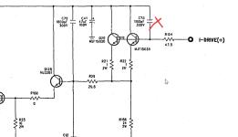
Hi everyone. XrayTonyB built a cool little tube amp kit from Douk Audio on YouTube about 4 years ago, and I want to try one myself. I haven't done anything with electronics in a while, so I want to check with someone who knows before I go messing with the circuit at all. It has two "magic eye" tubes in it that I really don't want. Since I plan to wire the kit point-to-point instead of using the included PC board for the audio portion, if I could eliminate those two tubes and the associated components, it would save me a whole lot of work.

Here is the schematic with the connections and components that I am considering eliminating marked with red. Can anyone confirm that I am not going to mess anything up in the other parts of the circuitry by doing this? Sometimes weird dependencies happen. It seems to me that they are completely isolated from everything else.

I would just ask XrayTonyB since he is a member here, but I don't seem to have the ability to send private messages to anyone. Link to his build videos: Login to view embedded media
With his few small mods, I think it would be a neat little amp for me to build. It tested good after he built it and put it through a series of tests on his bench.

Also, has anyone built this amp recently? Does anybody have one that they built recently, and if so how do you like it? It seems that current versions eliminate the loudness control that XrayTonyB cut out of his when he built it, but I haven't been able to confirm that yet.

Edit: updated schematic to show final values.

amplifier schematic wo magic eye - actual values.jpg
  • Like
Reactions: m0rten

WTB KSA1220AY for M2x IPS6 build

It appears the KSA1220AY parts for the M2x IPS6 boards are no longer available in small quantities.

Does anyone have these on hand in the USA that is willing to sell/share enough for 10 PCBs (10qty)? I will share the extra boards I ordered from JLCPCB and the KSA parts with others at cost.

I believe I can acquire all the other parts myself, so I just need the KSA parts to finish up a complete BOM.

Cheers!

ICEpower 300A2 dcerr sent to MicroAudio SMPS immediately

Greetings and Good Day!

After many years, I have finally got around to finishing my 8-channel amplifier. I will post pictures soon, to aid in troubleshooting.

Components used:
SMPS: MicroAudio Cobra-S2 https://micro-audio.com/store/product/cobra-s2/
^Datasheet: https://micro-audio.com/store/wp-content/uploads/2022/05/COBRA-S1-1.pdf
Amplifier Modules (4): https://shop.icepoweraudio.com/product/300a2/
^Datasheet: https://shop.icepoweraudio.com/wp-content/uploads/2024/04/ICEpower-300A2-Datasheet-1.4_.pdf

The issue is as soon as I turn the SMPS on, it goes into protect mode.
This only occurs when an amplifier module is hooked up. It will sit, powered on with no errors if no amp module is connected. Therefore, I feel the module is sending a DCError signal to the SMPS, sending it into 'protect' mode.

BEFORE I hooked up the SMPS to the amp module, I verified all voltages:
1739649490749.png


I do not have anything hooked to the 'Basic+ Control Connector', as I am not using BTL. Perhaps I need something from this section hooked up to the SMPS?
1739649649120.png


I also am not using the 'Aux connectors J4 & J5' on the SMPS. I didn't see anything here I needed. There is a pin for FATAL (error/fail) but so does the J3 connector (and evidently it is working, as it is sending the SMPS into protect).
J4/J5 (not in use):
1739649888115.png

J3 (HIGHLIGHTED pins in use):
1739650087703.png


Perhaps I need to hookup J3:5 and J3:6 above? 'Amplifier enable (Opto isolated) E' and 'C'??? I could not find anything on the amp module that made sense to hook them up to.


I really appreciate anybody's help in advance--I'm definitely confused!

Thank you!

advice upgrading output transformers and coupling caps in preamp

Hello everybody, I hope everybody is doing well. I recently purchased line stage 6sn7/300b based pre-amplifier. It uses toroidal power transformers as outputs transformers. The sound of the pramplifier as it was received was ok but not exceptional compared to the LTA pre I have been using. To see if the SQ improved I bypassed the input select rotatory switch, the balance potentiometer and replaced the remote controlled attenuator with a Goldpoint ladder attenuator, replaced the gain adjust potentiometer with a simple voltage divider circuit. The SQ has improved a good amount but not quite to the LTA pre level.
Can you advice on improving the output transformers? the ones installed are meant from converting 120/115 Volts 50/60 Hz to lower voltages for regulated power supplies. I am curious about kind of bandwidth of these transformers have when used in the audio frequency band. I guess I could buy the 2 models used and run a test...
The other potential improvement is to replace the coupling caps, installed are metallized propylene (MKP) in parallel with a paper in oil caps. All theses parts the potentiometers, selector switch, attenuattor and capacitors are common inexpensive parts.
I know the design is good and the preamp has the potential to get better SQ from it. Thank you in advance for your replies. I am interested on learning more about tube amps in general. Take care.

Transformer with dual primaries but one is center-tapped - why?

With one of my RYTHMIK subs (bought as a kit) when I plug the power cord into the IEC input there is a flash.

Been going on for a few months and decided to take a look yesterday.

These have an input voltage switch and when I took all of the shrink wrap off of the switch it did look suspect.

So I start to map out the wiring and it doesn't look like anything I have ever seen, which is not saying too much. I look on the transformer and it says this transformer has two primaries but one is center-tapped. I have never seen that before which helps explain my confusion.

Easy enough to identify what is what - I feel confident I have it wired with the primaries in parallel but wonder if anyone can explain why this arrangement? Does it have something to do with the dual input voltage? I cannot imagine why this would be needed. Is there a country with 180 volts AC? Assuming center tapped mean it is in the center.

Before I turn it on I would like to know if there is something I am not aware of.

If someone knows the information it will be appreciated.

Thanks and take care,

SWTPC Universal Tiger Improved And Simulation

I decided to simulate the SWTPC Universal Tiger using newer high speed, high beta output devices. Here is an old thread with the schematic: http://www.diyaudio.com/forums/showthread.php?threadid=41926

It does not simulate well with the original output devices, lots of crossover distortion and so on. However, I don't trust the On-Semi models for the old devices. The newer devices make a dramatic improvement. I was only able to do this using Andy C's improved, actually degbugged, models for the output devices, thank you AndyC: http://www.diyaudio.com/forums/showthread.php?s=&threadid=20460&highlight=

I don't know if I'll finish this, but attached is the LT-SPICE model for the improved output stage. I doubled up on output devices so that it will be safe driving 2 ohm loads, and increased the driver bias current. I suggest rail fuses for protection and of course a front end is required. I don't trust the output stage for thermal stability, it should be analyzed. I thought people might be curious to see it in simulation.

Andy's models must be added to the LT-SPICE library, as well as these below. Anyone checked the mje15034 and mje15035? :

.MODEL mje15034 npn IS=3.92866e-12 BF=260.938 NF=1.02215 VAF=15.3399 IKF=0.160087 ISE=1e-08

NE=2.54491 BR=26.0938 NR=1.10885 VAR=153.399 IKR=1.60087 ISC=1e-08 NC=1.89024 RB=0.41209 IRB=0.1

RBM=0.41209 RE=0.0001 RC=0.208002 XTB=0.897431 XTI=1.39234 EG=1.206 CJE=1.61534e-09 VJE=0.698417

MJE=0.382854 TF=1.03079e-09 XTF=1000 VTF=100000 ITF=42.9041 CJC=1.04458e-10 VJC=0.441587 MJC=0.23

XCJC=1 FC=0.8 CJS=0 VJS=0.75 MJS=0.5 TR=1e-07 PTF=0 KF=0 AF=1


.MODEL mje15035 pnp IS=5.81508e-15 BF=313.373 NF=0.85 VAF=40.5017 IKF=0.897023 ISE=6.74258e-16

NE=1.04249 BR=0.958017 NR=0.894461 VAR=148.639 IKR=7.05393 ISC=6.74258e-16 NC=2.84461 RB=3.62039

IRB=0.1 RBM=0.1 RE=0.000923293 RC=0.233799 XTB=2.92628 XTI=1.01325 EG=1.17461 CJE=1.5597e-09 VJE=0.99

MJE=0.554057 TF=1.35882e-09 XTF=1000 VTF=467.207 ITF=58.3338 CJC=1.58888e-10 VJC=0.4 MJC=0.23

XCJC=0.786287 FC=0.8 CJS=0 VJS=0.75 MJS=0.5 TR=1e-07 PTF=0 KF=0 AF=1

Pete B.

Attachments

Windows XP install disk

Does anyone have a Windows XP install disk they could give or sell me? Or a copy with the password decrypted.

I need a pukka XP machine to run the software I wrote myself in da last Millenium. Yes. I've tried the various Virtual machines but none of them give me the functionality I need. To put this into perspective, I run a DOS window under Win 98 on the XP machine.

Machines that have XP drivers are all more than 10 yrs old. I found one but I lent my pukka XP install disc to a friend who promptly lost it :stop:

For Sale Duelund Carbon/Silver resistors and Path Audio Resistors

Hello all,

Purging some audiophile resistors used in speaker crossovers, all have a 10W power rating. Leads are plenty long for use. All are 50% or more off from retail. All include shipping/Paypal costs and will ship to USA/Canada. I will also take $100 for all the resistors listed below.

UPDATE: ALL RESISTORS SOLD!

Duelund 1R2 [black] - $15 each (2 available)
Duelund 2R2 [brown] - $10 each (2 available)
Duelund 6R0 [brown] - $10 each (2 available)

PathAudio 3.9 ohm - $15 each (2 available)
PathAudio 6 ohm - $15 each (2 available)

Thanks for reading!

Best,
Anand.

Attachments

  • IMG_1059.jpeg
    IMG_1059.jpeg
    723.3 KB · Views: 114
  • IMG_1060.jpeg
    IMG_1060.jpeg
    611.4 KB · Views: 105

Yet Another QUAD II Restoration

I recently could acquire a pair of Quad IIs in need of restoration for a very decent price although without the tubes. I want to share my thoughts on and experiences during the restoration and would of course like to get a few opinions.

IMG_6145.jpg


IMG_6146.jpg

IMG_6147.jpg


Both amps are not very clean - pictures of one of them are attached. One of them (pictured) had at some stage the resistors and the cap on the tag board replaced. It also has an additional fuse for the power tubes. The other one seems pretty much original with all the original resistors and caps.

My goal is to keep the amps as much in an original state as reasonably possible and do not make any irreversible changes, which of course rules out any changes to the chassis and keeping all the original parts even if they are no more used. On the other hand I will do an upgrade to modern safety standards which implies proper use of mains ground amongst other things. I will not use the Quad 22 preamp.

Chassis:I will add a notebook style connector with 3 poles using a 3d printed adapter. The fuse holder will be replaced by a modern one and fitted with a 3d adaptor. A mains switch will be put in the opening of the old mains connector again with a 3d printed adapter and finally a RCA socket in place of the 6 pole connector again, guess what, with a 3d printed adapter.
The chassis must have been spray painted at some point in the past and cleaning it removes the paint anyways, so a repaint is in order.

Tag board: Here I am yet unsure if I should replace it completely with a PCB or try to clean it and just replace the components - it is really very grimy. Any opinions?

Power tube sockets: Yet unsure if I should reuse them or replace them with either screw mounted sockets or also creating a small PCB. Currently I tend to reusing them.

Wiring loom: There may be some risk of broken insulation, but I would take the risk if I keep the tag board. Of course it is also grimy....

Filtering caps: They are no more in really good shape, so I will probably create a PCB for it and a 3d printed holder which fits in place of the old canned caps.


There would. of course also be the option to create a complete new PCB with all the tubes using the original circuit and mount that together with the original power transformer, output transformer and choke onto a new chassis. But even thinking about it amounts to heresy I guess....


Toni

Speakerbench

In this series of posts I will give an introduction to SpeakerBench. The presentation is based on a 2-part article Claus Futtrup and I wrote this year for audioXpress magazine. Rather than a general discussion, we focus on a specific application: leakage loss as identified with our proposed advanced transducer model. The advanced model is compared to classical Thiele/Small modeling, with reference to detailed in-box measurements.

workbench.jpg
Projects by fanatics, for fanatics
Get answers and advice for everyone wanting to learn the art of audio.
Join the Community
507,689
Members
7,884,365
Messages

Filter

Forum Statistics

Threads
406,048
Messages
7,884,365
Members
507,689
Latest member
Giannikos