My 1st bass amplifier

Hello to all,

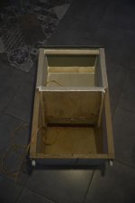
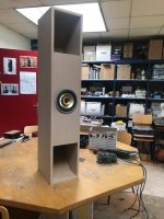
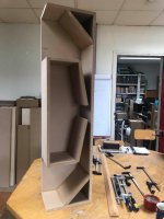
I've found a 8" speaker for 5€ and I need more SPL for my bass guitar, so i've
tried to do a low-cost woofer. It was like a DIY frenzy... I've learned about TS
parameters far too late during the process, and I'm not sure what the design
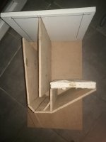
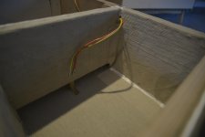
really is: my inspiration come from rear-loaded horns (cool wood-work exercice),
but with a 12L "box" before the horn. Maybe it's a labyrinth but my "horn"
section increases. The "horn" length is the only one thing i've done on purpose:
1m13 is 1/4 wave length of 73Hz, the speaker Fs.

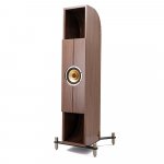
You can see the idea with "tobo1.jpg" to "tobo5.jpg" that show it during its
construction.

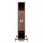
It's already a "win" for my learning process, but I found the result not too
bad for "loud hifi", and even quite good as a bass guitar cabinet. So I
share this there.

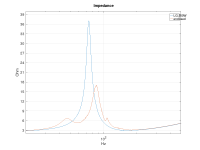
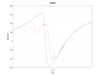
The speaker is LG branded, 3Ohm, 200W, impedance measurement give me Fs=73Hz,
Qts=0.82, Vas not done. Impedance / phase measurement attached, with the speaker
in free air, and in the 1st cabinet build.

My test bench is a low-cost class D 2x50W + 100W for the woofer. The bass filter
is set to its min for the stereo channel, and to the max for the woofer (no
precise spec sorry), thus all the bass come from my woofer under test. Then I
push the volume up until I can "ear a distortion", so it really depends on the
track played: Herbie Hancock's "watermelon man" is less "bass forgiving" than
Gesaffelstein's "Aleph".

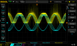
With my 1st attempt, I have 92dBA SPL at 1m, for 80Wpeak measured (snapshot from
my scope "scope_first.jpg" attached), above this level I can ear noises from the
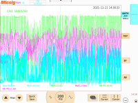
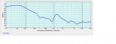
cabinet (leaks and vibrations). I've done a quick SPL measurement, in
"chirp_sum.png", I've captured response from the speaker and from the event.

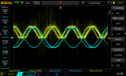
After some screws, glue and work, the 2nd attempt is louder: 98dBA SPL in the
same conditions (100Wpeak, see "scope_2nd.png")... Now distortions come from the
speaker that reach its Xmax, and things in the room that vibrate. No time for
now for more measurements on this version (impedance, spl...).

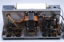
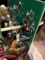
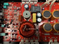
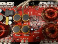
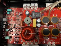
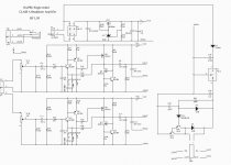
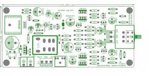
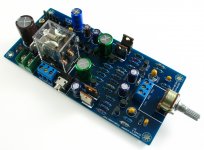
Next its amplifier...

Attachments

  • chirp_sum.png
    chirp_sum.png
    17.7 KB · Views: 109
  • impedances.png
    impedances.png
    11.7 KB · Views: 113
  • phase.png
    phase.png
    12.6 KB · Views: 98
  • post1.txt
    post1.txt
    2 KB · Views: 94
  • scope_2nd.png
    scope_2nd.png
    58.1 KB · Views: 105
  • scope_first.png
    scope_first.png
    40.6 KB · Views: 105
  • tobo1.jpg
    tobo1.jpg
    268.4 KB · Views: 108
  • tobo2.jpg
    tobo2.jpg
    148.7 KB · Views: 107
  • tobo3.jpg
    tobo3.jpg
    97.3 KB · Views: 109
  • tobo4.jpg
    tobo4.jpg
    133.6 KB · Views: 109
  • tobo5.jpg
    tobo5.jpg
    132.6 KB · Views: 126

Brainstorm with me - How to use ARC Chassis/PS?

So I'm at a point where I would like a new project and I feel like this dead Audio Research amp from the 80's is where that project should live. What I'm looking for here is suggestions on plans (or kits, pcb's etc...) that might fit in the chassis. If it could use the existing power supply that would be even better as it's beefy as hell.

Some details:
Existing power supply main DC rails are +/- 50V (one pair for each channel) with a 60VDC 30,000uF cap each (2 in total).
Also has a +/- 75V supply with a pair of 1900uF caps each (4 in total), this goes into the "tracking regulator" circuit that gets +/- 55V and +/- 15V
Here's a link to the schematic for the power supply, it's for the earlier D100 but from what I have read they're the same power supply circuit.

The heat sink and potential output situation, so there are 32 mounting points for TO-3 transistors on this thing. So a design that uses that body would be ideal (probably not 32 though).

Chassis is about 5" tall and there's about 2" of clearance from the mounting plate for the transistors and the power supply. Kinda tight, but possibly doable.

I'm open to Class A, class A/B, hell class D if something would work well with that dinosaur of a power supply and sound good. Two channels, don't need tons of power but not opposed to it. Comfortable with a reasonable amount of tinkering, point to point wiring etc...

Now is this a fool's errand? Is wanting to use the original power supply a bad idea? I'm open to suggestions here and won't take anything personally. Also for anyone wondering why I don't just fix this, I've considered it, it needs the "analog modules" they made back then, some people have reverse engineered them but apparently these amps were kind of garbage even when they were perfect, also the guy that passed this along to me only knew that "one channel was out" so not sure if some of the 32 MJ15003/MJ15004's are dead.

Here's some pics.

Login to view embedded media

Q: Will we be bringing all the old content across?

TL;DR We will migrate all the old content.

Longer answer - we will bring over all the threads and posts. Some areas like the wiki that have fallen into disuse will be readable but that is all. They'll go into an archive.

We will delete some internal content related to the old forum that will be irrelevant such as how-to post an image on vBulletin etc.

Searching for Gamut D200 Mosfet APT20M19JVR

Hello to all
I have the Gamut D200 ( and the preamplifier of the same series ) for quite some years now. Last year a problem with home electricity damaged the Mosfets of one channel. The amplifier is at the repair man (the former dealer) but we cannot source new original Mosfets. Anybody can help? (there are a lot of equivalent counterfeit parts out there but i dont want to risk exposing my precious amplifier to them
Part number is

APT20M19JVR and made by advanced power technology and i have pictures to compare​

Thanks in advance for all help

FS: Heathkit IT-21 Tube Tester with Original Manual

SOLD: Heathkit IT-21 Tube Tester. The original assembly manual, connection diagrams, and an errata sheet dated January 17, 1964 are included. The manual includes the full schematic of the tester.

$150 USD + shipping. I take payment via credit card and paypal. I'll cover the fees. I get excellent shipping rates via FedEx and UPS so I can get it to you fast for a very reasonable rate. Please contact me by email (add @neurochrome.com to my user ID here) or toss me a PM with your country, city, and postal code and I'll get a shipping quote to you. I have included a couple of examples below so you can get an idea:

UPS Ground to Toronto, ON, M5V1A8, Canada: $32 USD
UPS 3-Day to Beverly Hills, CA 90210, USA: $49 USD

I have not tested this tester or even plugged it in, so I won't vouch for functionality. That said, the circuit is basically a transformer and a few capacitors and resistors, so even if it does not work it should be easy to repair. I will leave that for the buyer, though.
The tube chart is clean and reads clearly. The adhesive tape has released from one of the rollers but that should be an easy fix with some acid free picture tape. Again; a project for the buyer. 🙂

This tester was built "back in the day" by Fred, the father-in-law of one of my best friends. The workmanship looks good. All the knobs and switches appear to function as intended. As you can see from the pictures this tester is in excellent condition.
The manual shows some age, but appears to be intact. The pages have been marked as Fred checked off each completed item. Those marks aside, the pages are clean.

Tom

Attachments

  • IT-21_1.jpg
    IT-21_1.jpg
    217.6 KB · Views: 150
  • IT-21_2.jpg
    IT-21_2.jpg
    245.5 KB · Views: 157
  • IT-21_3.jpg
    IT-21_3.jpg
    217.6 KB · Views: 149
  • IT-21_4.jpg
    IT-21_4.jpg
    177.1 KB · Views: 145
  • IT-21_5.jpg
    IT-21_5.jpg
    187.5 KB · Views: 152
  • IT-21_6.jpg
    IT-21_6.jpg
    209.9 KB · Views: 141
  • IT-21_7.jpg
    IT-21_7.jpg
    198.1 KB · Views: 133
  • IT-21_8.jpg
    IT-21_8.jpg
    193.5 KB · Views: 140
  • IT-21_9.jpg
    IT-21_9.jpg
    167.5 KB · Views: 141

What kind of LED would these be... now you are intrigued.

Long story short...

100 led string of Christmas lights fed from a 3 x AA cell controller that has 8 different flash patterns. It is a two wire set up with red, yellow, green and blue leds. Red and yellow are connected in parallel with one polarity and blue and green are fitted with opposite polarity. The chain is fed from what must be an H bridge driver with one polarity lighting one colour group and the opposite polarity lighting the other group.

Testing a single red led shows a forward voltage of 2.4 v (begins to glow) and 2.8 volts (20 ma flowing). These forward voltages are very high compared to normal red led's we might buy which have voltages around 1.58 and 1.88v under the same conditions.

So how do these led's work so well in that normally any difference in forward voltage would mean one led would be super bright and other dim. There is no visible resistor within the led but in any case that would not account for the red led needing such a high forward voltage. All 50 (one colour group) all illuminate evenly when a DVM on either diode range or low ohms range is connected to the wires. That small and low current test voltage from the DVM is enough. And all are evenly lit.

Are these specially manufactured led's for this type of usage?

Screenshot 2021-12-18 101709.jpg

Mute

Yes, many threads generically on mute, repairing mute, but I have not seen a full description of all the catch-22's and solutions to do it well.
Many use relays. Issues, some resolvable, some not
Many use FETs or similar. Again, not without issues
But how big are these issues and how well mitigated?

Problem: Crossovers ( single supply) produce a speaker blowing thump on both power up and down.
Yes, one can stand around and wait to turn on the amp. ( I have a sequencer, so I sort of to that)
But, not only I impatient, but it does not resolve a power interruption.
So it needs to be a slow pic, fast drop kind of circuit. Soft switching, and not causing distortion to the signal as most FET designs can do.
Opto-couplers don't seem to have a high enough "off" . Stacked? But does that add Johnson noise? Various configurations of bleeder resistors, but again, noise, distortion etc.
The mute does not have to be perfect, just good enough. Drop has to be faster than the supply collapsing. Pick after the supply is stable and DC blocking caps are happy.
Modern low level circuits are in the .00-something or less distortion. Even my power amp ( mine, not the Parasound I am using) is even better. So small parasitic issues are relevant.

I have thought about cutting up the board and doing a tracking supply, but that is not perfect either. A good circuit could be used for either low level, or to pick a relay for speaker outputs. My old Creek does pop a bit.

Perfect active travel speakers. Considering Tannoy autograph mini drivers for £250, or genelec 8010, or small active monitors.

Im looking to buy or build travel speakers.

I like coaxial or full range best but I am considering genelec 8010, tannoy autograph mini drivers with folded horn cabinets I might build and make into active monitors. Bi-amped.

I like the sound of tannoy hpd385s
I also like full range speakers.

Anyone have any advice as to what to do?
Buy the drivers for 250 and build them or are there already perfect travel speakers out there that will sound better for £500 or less

Thanks,

Philip

Using batteries for plate voltage

Hi,

I was thinking about whether it would make sense to design a power supply for plate voltage using batteries (LiIo, LiPo, LiFePo...).
I Know battery supply is a thing with solid state preamps especially high-gain phono stages. But I have not seen much in this regard with tubes.

I also know there are some types of tubes that were specifically designed for battery based operation in portable units back in the day. Here I'm more thinking about using our standard 12AX7, 6DJ8, etc... so B+ in the 100-200 V range.

We could design a power supply that manages the indivudual cells in a smart way (using a micro controller) and decides which cells to charge and which cells to use for power supply. So we need to put in more cells than we need for the maximum B+ Volatge that we want so we could always re-charge some of the cells while we use the others to supply volatage. We would need to have somthing that evens out the output volatge when a re-charged cell is brought "on-line" and a discharged cell is then taken of-line for re-charging.

So my theory is that this could yield an almost perfect DC voltage source using ca. 45 Lithium cells (for 3.6V each) in series for 160V. We can cluster them together in groups of 4 and hook those up to individual charging controllers. Given that that amounts to a huge capacity (assuming around 2000 mAh per cell) we probably don't even need to think about a scheme for charging some batteries while discharging others. 45 cells would combine to
90,000 mAh and if we power 4 double-triodes that maybe draw 20 mA each those cells will last for more than 1000 hous.

So the question is just , is it worth it for a high-gain phono stage? I'd say we wouldn't be powering the heaters from the batteries just B+ and maybe a CCS if we want that for our design.

Thoughts?

Cheers,
Lars

WTB Vintage headphones , mainly quadraphonic or ones with huge ear cups.

I am looking to buy any used vintage headphones. Drivers do not need to work. I don't want a beaten to death one either. A decent headband, cups , and maybe earpads(but I'm sure I'd swap them out) is what I'm looking for.

Wiring I don't care about either. PM me anything , worse I can say is now. I am also located in the USA so that's where I'd like to purchase from since I don't want to wait who knows how long for them to arrive from overseas.

Thanks!

Speaker protection circuit questions

Hi!

I am trying to build a speaker protection circuit with relay, doing protection against DC offset, delay at powering, and AC loss detection.
It is for a mono amplifier, with +/-20V power rails, and is based on Douglas Self circuit.

There are some things that I am not sure about. I am not familiar with switching circuits.

Q5/Q6 and Q13 discharge C8 throught R25 when power is removed for Q13, and if there is DC at the output for Q5/Q6. Could I connect them like this, or do I need one or two diodes to isolate them from each others? If yes, should I use pull-up resistors too?

I am not sure wich value choose for R25. It should limit the current, but as the discharge of C8 is really fast, I think I could use lower value as the transistors will dissipated power for a really short time.

I don’t really know how to choose the maximale value for R22 too. It limit the base current of the DC detector transistors, but as we don’t know wath he value of the offset will be, I don’t know how to calculate it.

For the loss of AC detector, Douglas Self said that C2 should be an electrolytic capacitor, but I don’t understand why, as in my simulation it work well with a 1uF capacitor. For now I have just use (only in simulator) random value with no calculation, it seem to work well but I have probably overlooked something.

There are probably things that could have be done better. Any critics would be really appreciated!

Thanks a lot for your help!
Please apologize my bad english.

Attachments

  • diya.png
    diya.png
    43.4 KB · Views: 674

Which SB woofer

Which SB woofer (or alternatives) for a 35liter sealed box crossing at 500-700hz.

SB29NRX75-8 is fairly new I think with no hits on a google and gives the same profile in WINISD as the WO24P-4, is 8ohm, has a larger SD, a couple more mm Xmax and looks like a more benign breakup but drops 3dB in sensitivity.

Has anyone heard or worked with the SB29 8 ohm, what do you think ?

Which would you choose, if neither then what else ?


10″ SB29NRX75-8 / Norex - Sbacoustics

91/2″ SATORI WO24P-4 / Paper - Sbacoustics

How to measure speaker spl

I'm curious to get peoples views and opinions on how you should measure a speaker - specifically spl.

I accept that the standard distance is at 1m ..and that a lot of people aim for a flat response, but the reason I raise this issue is that I doubt that many people listen at 1m (bar those using nearfield monitors) and since the response curve will change (quit a bit in some cases) as the distance from the speakers increases, would it not make sense to be measuring at the listening position?

I guess that would give rise to determining a different standard measurement distance, which may be impossible due to the range but then why is it generally done at 1m?

VU meter and buffer circuit for amp - compressing readings logarithmically

I recently purchased two mystery VU meters from Amazon that I’d like to install in my F6 (I'd link to the ones I bought but they are no longer available). I’d like to drive these meters off the amplifier inputs rather than across the speaker outputs. The meter looks like a Sifam presentor meter, but it doesn’t react to an AC signal w/ a 3.6K resistor in-line, as the Sifam meter claims it should. It seems the meter does not have internal rectification.

So I purchased a JLM audio VU2 stereo buffer PCB kit. I don’t have a schematic for the kit but it includes a dual op-amp, adjustable potentiometers, and diodes to rectify the AC signal to DC. Conveniently, it also has headers to provide 12VDC to the lamps in the meters.

The meter works with the buffer kit (I did have to replace two 3k3 ohm resistors with 680 ohm resistors on the buffer PCB to provide more gain, per Note 3 here in the build instructions) but it appears to respond in a linear, rather than a logarithmic fashion.

The problem of course is that the meters react barely - or not at all - at normal listening levels and peg during loud peaks at medium-to-load listening levels. What I’d like to do is to create a logarithmic circuit in-line between the buffer board and the meter that will compress the range of the meter across a wider range of input signals so that the both quiet and load signals read on the meter. Something similar to what is proposed here, but tailored to the specifications of the meters in question and designed for a (much) lower-level signal rather than the speaker-output signal.

I’m hoping that folks here might be able to let me know whether it is even possible to create a similar circuit w/ diodes for such a significantly lower range of input voltages and run it in-line with the buffer kit. I’m still relatively new to this hobby and currently working my way through the Art of Electronics but I haven’t learned enough yet to solve this problem on my own.

I took a bunch of measurements of the meter being fed a 1KHz signal from my DAC/preamp through the buffer board. I measured the current being fed into the meter, the average voltage across the meter terminals, and the RMS voltage of the input signal into the buffer board. (I took a few other measurements, all of which can be seen in this Google spreadsheet).

It seems the meter has an internal resistance of around 50-60 ohms. It measures ~51 ohms with a multimeter. Based on the measured Vavg values across the terminals correlated with the measured current the impedance at 1KHz is ~59 ohms. It appears to reach full deflection with 1.15mA of current and a +3 reading with exactly 1mA.

I've attached a table of measurements and some charts (the scale is a bit weird given the VU measurements, forgive me) as well as an image of the front face of the meter.

I've also attached two screenshots from the scope. One shows the meter at VU reading 0 - yellow trace is the signal across the meter terminals after rectification by the buffer board. The blue trace is the input signal to the buffer board. Note the different scales and readings. The second shows the same at reading +3 (nearly full deflection).

Attachments

  • table_of_data.JPG
    table_of_data.JPG
    34.3 KB · Views: 736
  • current_vs_reading.JPG
    current_vs_reading.JPG
    29.3 KB · Views: 700
  • input_v_vs_reading.JPG
    input_v_vs_reading.JPG
    25.7 KB · Views: 680
  • v_terminals_vs_reading.JPG
    v_terminals_vs_reading.JPG
    28.7 KB · Views: 656
  • VU_meter_0_position_1.png
    VU_meter_0_position_1.png
    81.6 KB · Views: 706
  • VU_meter_3_position.png
    VU_meter_3_position.png
    88.9 KB · Views: 256
  • meter_face.JPG
    meter_face.JPG
    23.4 KB · Views: 327

Help with Polk DSW1000

realizing this may not be the right forum, but hoping an electronics whiz can help a brother out...

I have a Polk DSW1000 subwoofer w/ a built-in amp. The amp powers on OK, but will not start producing sound until after it has warmed up for anywhere between 10 and 30 minutes. After that time, it is not unusual for it to kick in for a second, then kick out, then kick in for 2 seconds, kick off, etc until it finally outputs sound continually, and then it will work OK until I power it off & let it cool down. Re-powering starts the process over again.

To my fairly novice mind, this seems like it might be a capacitor, so I pulled it apart today to look for any obviously bad (i.e. leaking) capacitors. I did not find any, but I did find two that have their tops swollen, and I wonder if they might be it..

Does anyone know the best way to troubleshoot those? I can de-solder them & put in new ones if I need to, but hoping there was maybe some way to test them while they are still in the unit?

Or, does it sound like I am off on my diagnosis, and maybe it's something else? Any suggestions on where to start looking? I can use a meter, but am not super versed on electronics. If I could find a shop to send it to, I would, but I can't find any shops that will work on it for some reason.

Thank you so much for any replies! I am attaching some pics of the two suspect caps...

Attachments

  • Cap1.jpg
    Cap1.jpg
    437.5 KB · Views: 197
  • Cap2.jpg
    Cap2.jpg
    364.1 KB · Views: 200

High Quality Streamer

Hello,
I have never posted to the Digital Forum before...In fact my knowledge of digital audio is VERY limited. I'm passing along a question from a friend about his streaming
capability. Presently he's using the DAC built in to his McIntosh C2700 Preamp being feed from a blue sound node 2I. What would be his path for a better overall digital experience via streaming audio?

Marshall JCM900 4500

Hi,

My 50W JCM900 (4500 dual reverb) head, driving a 1936 2x12 Cabnet, has started misbehaving. The weapon of choice was my 1960 Les Paul Classic (re-issue).

While playing at lower volumes eariler (on both chanels), the amp faded down to no sound. I waited about 10 seconds, and sound would return again. I'm not sure where to start. Are there good documents available for the circuits of this amp? Are there any experienced members here?

Also, semi related, has anybody around here came up with a DIY attention circuit? Something like a power brake used to accomplish?

Cheers,
Tim

Modify lug/ ring terminal connectors for speaker connection?

Hi,
I'm searching for banana plugs replacement and wanna try spade/fork connectors. This is to be used with vintage amps and 20 year old speakers.

While searching, I found out that most spade and banana plugs are made of brass. The copper ones are more expensive. However, I also found lots of relatively cheap with 99% copper lug/ ring terminals. I wonder that anyone has tried to use those instead of commercially available pure copper spade/fork connector?

https://www.amazon.com/s?k=lug+terminal

The thick one comes with ring/ lug shape which rated for 50A - 100A of pure copper, but they needed to be cut open (dremel?) to be spade/ fork shape in order to be used with typical binding post. I will solder the wire and tin whole connector with silver soldering lead to reduce oxidation.

Those may have zero "audio grade" snake oil but my guess it still should be better than aliexpress brass banana plugs?

Your thoughts?
AP

Strobe Lights and Bass

Hi all,

As some of you know, I recently completed my 2 Peavey Low Rider 18" subs thanks to guidance from here. So now, I've got another question that some of you might not be familiar with. I only have one subwoofer and 2 of my floorstanding speakers with me in my new apartment. However, they are both in our "party" room, and a few of us recently started to talk about the addition of strobe lights. We would only want them to go off during the bass hits. However, many of the strobe lights out there are based on a microphone, and I ould tend to think that when music is very loud they would constantly be on. However, we had an idea of somehow runing the strobes off the subwoofer amplifier, so they would only light up temporarily on the bass hits. I was wondering if it is at all possible to simply put 4 strobes in series and connect them to the terminals of the unused chanel on my EP2500. With some quick math I found some strobes that are 1.5 ohms in resistance, so 4 would be a 6 ohm load, and the EP2500 can handle all the way down to 2 ohm loads. But I could even add a resistor to make it an 8 ohm load, and since each bulb can handle 125watts, that would be an 8 ohm load at 500 watts, which is exactly what the EP2500 can put out. Still, theres the matter of current. According to the EP2500 manual, It draws 9.6A in regards to power consumption, and then it says 5A at the mains connector. Basically I want to know if you guys think this will work or if theres an easier way to set this up for a relatively small price, as I dont know too much about lighting and effects.

Thanks guys

Sundown SAE-1500D

Amp is producing rail and regulated voltages .

Amp has output but it’s very distorted like someone is farting through the test speaker .

Any idea on where to start looking since everything I’ve checked so far tests fine

Attachments

  • 0651BF18-8BED-49AD-A0FF-DEFFF1B7A0ED.jpg
    0651BF18-8BED-49AD-A0FF-DEFFF1B7A0ED.jpg
    1 MB · Views: 273
  • 5332842F-B8FA-4DC4-99CB-0630B19B30DA.jpg
    5332842F-B8FA-4DC4-99CB-0630B19B30DA.jpg
    1.1 MB · Views: 302
  • 3E0D9133-F023-465B-B1F4-F76CF764002D.jpg
    3E0D9133-F023-465B-B1F4-F76CF764002D.jpg
    1 MB · Views: 260

First own DIY project tube preamp with phono MC/MM and Muses 72320 for Volume control

Hello all,


to be honest this is my first real post on diyaudio.com although I'm a passive reader for quite some time.
I have had some spare time due to the current world wide situation.
So I was thinking about to start a project to aquire new skills and I have had laying around some old tubes, housings... which were not in use.
So I downloaded KiCad and Micro-Cap 12 (which is available for free now, as you might know)


At the end I came up with an MM phono stage using 5751 and 6922.
The MC stage will be some sort of Xono MC stage (I'm not quite sure).
For the line stage I decided to use 5687 followed by an Allen Wright SLCF with 6922.
Power supply will be separated and some shunt regs a la Salas will be used if he don't mind.


Since I like it comfortable, I planned to make everything controllable and switchable (source, phono loading, volume etc) with a µC and also via a remote control.
After the first steps in KiCad I finished a "controller board" and sent the gerber files to a PCB manufacturer.
Please keep in mind that I am abolutely not an professional and I am just learning by doing.
Hence any feedback of you is very welcome!
Next step would be to finish the "input board". During the manufacturing process I would have some time to finish the µC routines.


Here I would like to ask for your help 🙂
The "input board" should include source switching, phono loading switching and the volume control with the muses 72320 chip. (You can find the first schematic of the muses chip in the attachment)
Following questions showed up, where I have no clue:


Muses 72320:


1.) How important is quality of the +/-15V supply for the chip?
2.) Would a +/-12V supply have major disadvantages?
3.) Would be some kind of galvanic isolation helpful for the SPI bus? (If so, which chip would you recommend?)
4.) Looks the schematic in general "okay" for you?


Source switching:


I am still thinking about what would be the best way for source selection.
I mean, for example the GND handling. Should I also disconnect the GND of unused sources? If so, which trouble I am running into? (mute relays etc. are already included)
Or would it just be okay to switch unused sources via a defined resistor to GND?


For the beginning this would be my first questions to be able to continue with this project.
I'm sure it will be a long way and I am very exited if I will finish it. 😀


So thank you very much for your help and your support in advance!


Please stay safe!!!


Falk

Attachments

  • Controller_Board.jpg
    Controller_Board.jpg
    834.1 KB · Views: 767
  • PCB.jpeg
    PCB.jpeg
    553.7 KB · Views: 671
  • PCB_working.jpeg
    PCB_working.jpeg
    500 KB · Views: 729
  • Muses.jpg
    Muses.jpg
    201.3 KB · Views: 906
  • Like
Reactions: Vavilen

HA-PRO Single-ended MOSFET

CLASS A Headphone Amplifier

Some material, convenient friends of the production.


Need to pay attention to, it USES AC 24-0 input, low voltage will make failure noise voltage.

Had better not exceed AC28-0.


10 the resistance controls the MOSFET IQ,

About 650 MV / 10 R = 65 MA

It is a, very hot. Headphone amplifiers :flame:

Attachments

  • 1.jpg
    1.jpg
    140 KB · Views: 4,817
  • 2.jpg
    2.jpg
    252.5 KB · Views: 4,503
  • 3.jpg
    3.jpg
    290.4 KB · Views: 4,121

REL Qbass Hum

Hi
I have an old REL Qbass that has started Humming
I am using the RCA output from the rel in a 7.2 setup

I have connected a wire from the screw on the REL to the chassis on an AV receiver but this made no difference
I then tried to connect a wire to the REL front screw and touch My other subwoofer screw but no difference
I tried to ground My SKY box to the chassis of My AVR but no difference

As a test, I removed the earth from the kettle lead and plugged this into the REL and the hum was there but not loud
Also, something else I found interesting is that when I put the phase switch in the middle there is no hum

I will really appreciate everyone's help, please
Thanks so much

Sunfire Junior Subwoofer

I am very new to all things audio like this, so I have ran into a little problem. I've search online and came up empty so I'm hoping I could get a little help. My Sunfire Junior internal fuses have blown and need to be replaced. The problem is I can't find what type of fuse to replace them with. The fuse it's self says 4 amp 125 volt. I know I need slow blow, but all I can find is 4 amp 250 volt. Can I use a 250 volt or does it have to be 125 Volt? Thank you for the help in advance.

Rel q150e MK II

I am hoping someone can help me. This unit is about 15 years old. Has worked fine until recently. There is now a very faint hum whether it is connected to the inputs or not and whether the external amp is ‘on’ or not. I can live with the hum but more significantly, it occasionally rumbles or thumps (the first time we woke in the early hours convinced we had an intruder in the house!)

It hasn’t been used hard.

I am not an expert but can use a soldering iron and am curious. I have taken the back off to have a look at the circuit board and ancillaries to see if there was any obvious sign of overheating etc but it all looks like new.

I have no test equipment beyond a multimeter! Any suggestions for what I could try ? Failing that is there a good repairer anyone could recommend ? I am in south west London.

If it can’t be repaired is there a different more up to date amp that could be retrofitted and would do the same job ?

Many thanks

Sanity check - EL34 bias/numbers

I'm currently looking at a pair of mid 80s EL34 PP monoblocks on the bench (these beasts have 8 EL34 per block arranged in 4-4 parallel push pull). These had a few badly swollen capacitors, which were obviously in need of replacement and I've done that job. I wanted to do a check on bias etc to make sure all is OK, and that they are within reasonable operating parameters. Would someone mind just throwing their eye on the figures below to check all is OK (I think it is, but its near max dissipation):

Anode voltage 410V
Screen voltage 380V
Plate to Cathode 384V
Bias voltage -25V

Cathode resistor 470R (one per valve) - and running 27-29V or so over this.

That seems to work out at ~60ma, 23W and about 90% of rated maximum. Would that sound right to you?


Fran

TDA1541 Question - No Output

Hey all! Not much experience with DAC design, but got a question - I have a TDA1541 based DAC - all voltages appear to be per design. No output to OPAMPs...is it possible to have bad (fake) TDA1541 with all pin voltages correct?

DAC Input to CS8412, SAA7220 to TDA1541. LED lights for good Signal lock on TOSLINK and COAX Digital input. Just no output either channel

-13.7VDC output from Pioneer VSX-409RDS caused by mulitple grounds

-13.7VDC output from Pioneer VSX-409RDS caused by multiple grounds

I bought a broken amplifier again, but this time it behaves really strange. Now I understand the basic problems of amplifiers and this one doesn't seem to comply to those. It is a pretty cheap 5-channel amplifier from Pioneer (1999) using a 2 channel IA and a 3-channel IA.

The first problem I found was a blown fuse in the standby 12V+ part. I replaced it and it booted up, but I measured -13.7V at the Front Left and Right outputs. I guessed that this problem was most likely caused by a broken Integrated Amplifier and I replaced the PAC010A (2-channel IA). This, however didn't fix the problem, so me and my father searched for the problem, but couldn't find it. I did find a strange interference of two voltages (the IAs use a 55V+, 55V-, 35V+ and 35V- input). I read on the 35V- pin 45V-. When I removed the 35V- and 35V+, I still read 45V- on the 35V- pin. I found 7V+ on the 35V+ pin too. This only completely went away after removing the 55V+ and 55V- pins. When I removed the PAC011A (3-channel IA), I read 35V- on the 35V- pin and when I removed the connector that transferred the audio-input to the IAs, it was 38V-, so I just left it there. With that kind of solved, the main problem still wasn't solved. We found this amplifier had 2 separate grounds with a difference of 13.7V, when using the speaker ground as the main ground it was -13.7VDC. When again removing the connector that transfers the audio-input, it outputs -50VDC on the speaker outputs, so, again, I just left it there. What we can't understand is: how can those two separate grounds cause an output of -13.7VDC on the speaker output.

The Service Manual is here: PIONEER VSX-409RDS SM Service Manual download, schematics, eeprom, repair info for electronics experts

Wiring power supply and transformer for F6

Can anyone supply me with a some photos of a schematic for wiring up the power supply board and transformer to the F6? I have opted to use a board from ClassDAudio, http://www.classdaudio.com/large-hd-power-supply-1.html , populated with 22,000 microfarad capacitors for my project and the Antek AS-4218 transformer, but I can probably figure it out from the DIY Universal Board if necessary. It seems that the photos in the build guides and the links to pdfs are not working. I assume this is a temporary problem due to the software changover.

Phono Preamp Misbehaving

Hello and thanks for showing up. I've built a tube phono preamp using 5842s from a circuit by Joe Tritschler. It functions, but in use, the RIAA EQ is out of whack. The LFs are heavily attenuated, but other than that it sounds very good, quiet and clear. Testing showed the LED bias doesn't seem right and I'm pulling 8.3mA at the plates instead of the 15mA the design specifies. I'm also unsure about my 6.3V filament wiring. I've wired +6.3VDC to pins 3 and 0VDC to pins 9 (I know I didn't have to twist the heater wires, it's just force of habit). Can anyone point out any mistakes? The LED is the one specified in the article (https://audioxpress.com/article/borbely-riaa-preamp-with-tubes-project-remembered-and-revisited) should I try a different part? Attached is the schematic with specified voltages (mine are red) and a picture of the circuit as built.
RIAA-Preamp With Voltages.png
Phono Preamp Circuit.jpg

Raysonic SP120 help needed

Hello dear DIY mates!
I recently acquired an early SP120 integrated (not the Mk II), and I wonder if anyone could help me with some issues...
It functions seemingly perfectly, equipped with basic tubes (Raysonic branded -russian- 12AX7 and 6SN7GT-s) and Electro Harmonix KT120-s.
However I've heard about a certain "voltage" issue that can cause problems in the circuitry. I wonder if anyone has any info on this subject, and perhaps some possible areas of improvement beside the usual stuff (coupling cap and tube replacements).
Unfortunatley there is no schematic or service manual available for this model, and as I see the inside it is not really a simple design....
I would appreciate any help concerning this amp.

Help resurrecting Technics SU-X980D

Hi all left channel blown, suspecting the SVI3204 bad, beginner level here

Have replaced a few smaller caps also one of the main caps was bad, have replaced the 3 chips next to power unit hoping that would fix it but no.
Have seen someone add a separate amp board skipping the svi module and wondering for any advice.
Can't let the whole system down due to the amp it's been a valued companion for years thanks

Liionidas eXotic

After the Liionidas Open Baffle , I was asked by Lii Song to do something nice with their Crystal 6 driver.
After some prototypes I ended with a "double mouth big vent reflex".
The design is on the Lii site as a complete speaker.
I would like to share some photo's over here of the building and end result.
Please enjoy and be inspired.

I'm very happy with the sound.

sinc. Leon.

Attachments

  • dm bvr c6 2.jpg
    dm bvr c6 2.jpg
    68.8 KB · Views: 820
  • dm bvr c6.jpg
    dm bvr c6.jpg
    60.4 KB · Views: 932
  • Liionidas-eXotic-1.jpg
    Liionidas-eXotic-1.jpg
    122.6 KB · Views: 838
  • Liionidas-eXotic-2.jpg
    Liionidas-eXotic-2.jpg
    135.8 KB · Views: 800

Enclosure for 2 Faital Pro 15PR400

After attempting to get a good in-room response using Beyma 18p80nd (in 180l) actively up to 200hz I have come to the conclusion that I will get a better response (that sonically matches the B&C8ndl51 and Beyma TPL150 (without waveguide) using the Faital 15PR400 (all system to be driven actively). Although at present my funds are limited my intention long-term is to use 2 15" woofers per side. Room is 9mx5m and I listen to quite a lot of modern music that contains a lot of bass information (eg Lorde, Katy Perry - system is used by whole family). I have struggled to find information relating to using 2 bass drivers and few of the on-line calculators allow these calculations. I think I'll be happy with an F3 of 30Hz and probably an enclosure volume of around 360 litres. Can any of the experts on here guide me to enclosure design (?1 compartment per bass driver or both units sharing the same space) and whether I should be using 1 port or 2. When I have performed the calculations using a sealed box of 360 litres and a single driver I get an F3 of 80hz - which obviously means I need a ported enclosure.
Thankyou.
  • Like
Reactions: DblAA

Dealing with parasitics in passive LC filters

Filters designed from various tools or methods rarely deal with parasitic parameters of reactive components.
I need to include/correct for the inductors series resistance, mostly: I design a series of LPFs using exclusively air-cored inductors, to keep the THD well below the ppm level, but even with coils optimized according to the Brooks form-factor, this results in significant series resistance.

The simulated and measured effect of this resistance is to increase the HF losses, before the cutoff frequency is reached. It also increases the DC/LF losses of course, but in an easily predictable and compensable way.
I don't mind losing 0.5 or 1dB, as long as the loss remains flat for all of the useful frequency range. If I cannot achieve it, I will need to include additional equalization networks, which is annoying.
Is there a way to flatten the curve by tweaking the filter parameters alone?

Here is an example: this is the response of a 100kHz elliptic filter, with the actual 5 ohm resistance of the inductors included:
100Kfilter.png


From ~85kHz, there is a clear droop in the amplitude. When the inductors are perfect, there is no such droop, just the ripple inherent to this type of filter.
I informally tried various fixes and tweaks, but I only managed to further damage the response in other ways, without being able equalize the response.

I there a deterministic (and simple!) method to deal with this?

As a base, I rely on simple and effective design tools like this one: https://rf-tools.com/lc-filter/ but there is no way to include parasitics

MTX Thunder Pro 3002

This one has a stumping problem. Got it with outputs and emitter resistors blown in one channel. Replaced all IRF540 with IRF3710Z. Found Q21 junction open as well.

Amp was able to power and play so put it back in the sync. Everything went well with testing each channel individually but not bridged.

As soon as I bridged the amp at 4-ohm load and started to bring up the input signal, the amp pulled hard and popped all 3x30A fuses.

Broke back down, and found some of the new IRF3710Z outputs shorted. Also one of the PS Fets shorted. Q21, Q34, D42, D43, D44 and D45 at least have failed.


Is there a schematic available for this amp?

Why would it pop when bridged, but pull just fine with only 1 channel at a time?

F4 - tips on building details?

Hello,

a little while ago I got the two boards with the MOSFETs off the US and finally handed them to my friend's Ciro capable hands, the cabinet also made it to the lab and now it's about transformers, caps and all the other stuff.

I have no experience whatsoever on build and even tho I read tons of threads I don't feel skilled enough nor have the tools to build such a thing that's why I asked him, who is a very competent guy in this field to do it for me but there's quite a few thing I'd like to know before going any further.

We decided on a dual mono in a single chassis, two 225VA transformers (might be bigger depending on what's available at the supplier), capacitors I forgot what he mentioned but for the whole thing it will be in the 250 euros range (!!!), then I asked if a soft start is necessary but he said it is not, then since I want a front switch (any suggestion at where to look to have an idea of what to get? I guess typical are the round ones in Apple's style with coloured led light, I want the less flashy possible thing, I picked black 4U case and it HAS to match!) he said it will take a relais to command the power section.

What should I discuss before he jumps onto the build? Any hint you can get me?

By the way, still freaking because of my 90db/w speakers (Old JBL L220) and preamp, about same age, AR SP9, hopefully they match well together...


Thanks for your time

Giovanni

Audio Pcb Layout Techniques

Hi All,
I've designed a few pcb's for myself in the last year or two, and as happy as I've been with the results, I really have no way of measuring success nor a framework to think about improving designs. As such I suspect I'm really fumbling around in the dark and there's improvements to be made on what I do. I'm completely self taught in this, so I've probably developed a few random methodologies that would do the be debunked.

In terms of learing it myself, iterating through 6 versions of the same idea to explore the differences isn't a practical option. So my basic question is

What are the fundamental ideas behind quality pcb design?

I could attach a few pcb layouts I've done as example pieces to discuss if anyone is willing to constructively critique the improvements possible (they are all single sided as I make em at home via toner transfer). So if this is helpful, please say so. I would imagine working through a few examples would benefit anyone wanting to learn this art.

To date, all I try and do are
1. minimize length/proximity of presumed current flows
2. minimize parallel traces/maximise orthogonal crossing of parts
3. er...

So, advice or links are appreciated. Thanks in advance.

Expensive speaker DIY projects on the internet- wrong road?

I never had time to wrote about this sensitive issue and nearly forgot, but recently one forue member asked for speaker enclosure help. I gave quick look at drawing and found same issues.

in the past( in 2012 or so) I have expierence some strange DIY speaker designs (quite exenive ones ,costing 10KEUR+ in parts) from well known website.I would not want disclose that website, as this not some kind of actual critics, just more generalized outcomes.

Speaker costing more than 10KEUR and targeted to 70KEUR comercial brand speaker copy had very expensive in parts but quite strange design which leaded to very medciore sound. Actualy so medciore that a simple small reasonably priced(4000eur) standmount speaker outperformed it even in bass departament, not speaking to soundstage and all that audiophile stuff. I started to look if I made errors assembling speakers or some of the drivers are defected. however all was fine. I then sent email to designer, asking some specific questions regarding stranage internal volumes and some stange xover design desisions. shortly after this designer apologized and “ ultimate best sound project” were took out of website. I wonder how much people tried this ultimate project trying to “save money”? I have stumbled on more DIY projects with such outcomes , but this was most memorable. the drivers ,enclosure and xover parts quality was best of what i have ever seen. and i have seen a lot. when i open Focal Utopia speakers to see what inside it looked like cheap chinesse electronic market speakers comparing to this. B&W and even Magico Q crossovers looks "cheap".

I am not against DIY speakers, it fun , entertnaining and good performance can be achieved. I like them very much. However when we speak about high end level of performance DIY cant touch good comercial brands. And price performance ratio is much worse. Funny that most of DIY designs claims better or same sound for much lesss money. Reality hits hard on that when someone unbiased (no intention to either of objects) compares good brand speakers with DIY side by side. I believe one of the reason is versatility of brand spekers- they are tried/fine tuned in many room with many electronic by whole crew. while DIY speker fine tuned by(usualy) one person in one room.

my advise would be always have some well know brand speakers which you like in the same price range to compare with DIY speaker.

Clone of Accuphase C-27 (Project C-28)

Hi all,

just photos of my implementation of great Accuphase phone-stage C-27. I call it Project C-28 because it has only MC-section and there are some small changes in schematics compared with the original one. As for the sound - it`s great! Really.

I hope this may encourage someone uncertain in his forces in repeating the project and enjoy the great variety of music 🙂

Update 1. Schematic and gerbers can be downloaded from the following link: C-28.
Update 2. DipTrace files can be downloaded from the following link: C28_(2).

Attachments

  • IMG_4362.JPG
    IMG_4362.JPG
    134 KB · Views: 815
  • IMG_4363.jpg
    IMG_4363.jpg
    323.2 KB · Views: 763
  • IMG_4364.JPG
    IMG_4364.JPG
    288.2 KB · Views: 798
  • IMG_4365.JPG
    IMG_4365.JPG
    208.3 KB · Views: 733
  • IMG_4366.JPG
    IMG_4366.JPG
    288.1 KB · Views: 736
  • IMG_4367.JPG
    IMG_4367.JPG
    192.5 KB · Views: 404
  • IMG_4368.JPG
    IMG_4368.JPG
    208.9 KB · Views: 385
  • IMG_4369.JPG
    IMG_4369.JPG
    187.7 KB · Views: 396
  • IMG_4370.JPG
    IMG_4370.JPG
    207.9 KB · Views: 382

Newbie Headphone on parts to change speaker sound

Hi everyone!

Newbie and I”m here just trying to test and try all different methods to create a fun headphone.

As far as headphones go, can some of you direct me towards small pieces I can wire and solder between the speaker and amp.. I‘m interested as to what types of pieces I need to buy to cut off frequencies or how to lower volume to certain speakers.

Are there any guides or sites that teach this?

Just for fun I want to do a multi driver headphone and want to figure out materials, space, and if resisotors or capacitors. Are there any noobie guides out there?

How to change the needle on your Clearaudio MM for 30 euros

Disclaimer...
This applies to Clearaudio Virtuoso. Possibly for Maestro and the other MMs as well as some other guys report, but I cannot verify this...
This is strictly personal experience. Not at all professional. And it will probably void any guaranty on you cartridge, although I doubt it can be detected...
I am not responsible if you burn your house, your turntable, your aunt or anything around you while trying to perform this.

On to the fun part...

Clearaudio sell their MM cartridges as "non user stylus serviceable" as in "you cannot replace the stylus yourself".
Well this is partly true because you cannot find any Clearaudio replacement needles on the market. At least not for a reasonable price... But as it seems, and thanks to neobop from audiocircle and a few other clever people, we now know that it is possible... if you can override a few really minor obstacles...

First of all removing the stylus... I don t know what they mean "not user serviceable", but if you catch the black plastic stylus with some pliers and pull it, it just comes off... that easy... I don t mean pulling it like a moron.. carefully so that the small magnets do not scratch the walls coming out... although I would not worry too much... it seems pretty easy and straightforward.

Now that we got it out, we need a replacement. As it seems, Audio Technica is the OEM for at least some of the parts of the cartridges, including the stylus. The magic part number is AT95e and costs about 30 euros from ebay. You need the replacement stylus, and not the entire cartridge

An externally hosted image should be here but it was not working when we last tested it.


Now if you have already removed the clearaudio stylus, you have probably noticed that that thing is much bigger...
This is where the most minorlly tricky part is... we need to do some minor surgery to the AT95e.
If you compare the AT95e with the clearaudio, you can see that the AT95e is the clearaudio one with some more plastic attached to it. Basically you just have to get an exacto knife and cut the extra plastic right next to the needle carrier, so that you get a part that is identical to the clearaudio in size and shape. I don t have a photo, but if you look at it, it is pretty clear what you need to do...
You just need to take your time and do this patiently and you can get a pretty nice looking part. If you do it fast and sloppily it will still work (provided that you do not damage the needle suspension or the needle of course...), but it will look ugly...

And now that you have your brand new part, just push it gently in the cartridge body..
The thing fits so nicely that it will click in place, as if the parts were designed for each other... If you do it properly, you will have something like that...

attachment.php


You can see the original black stylus, the full AT95e replacement carrier with a pretty obvious idea of where you need to do a clean cut, and the new green stylus installed in its new home...

Sonically the audio technica stylus sounds amazing. I would not say that it sounds better or worse that the clearaudio one, but I can say with confidence that even if I had 600 euros burning my pockets, I probably would spend it on something else... like boose or women 😛

The only issue is that if you have a maestro, you will be replacing your boron cantilever for an aluminum one... But from what I read, you can also get a Shibata replacement part for around 100 euros.
The really interesting part, is that the audio technica carrier has a compliance screw... this means that the needle can be replaced...
And this opens a completely new world for your cartridge...

enjoy 🙂

Attachments

  • DIM_1920.jpg
    DIM_1920.jpg
    261.2 KB · Views: 6,920

1970's Tandberg Solvsuper SS11 Repair

I have this machine in for repair. On one channel the output amp is totally destroyed. All the Semiconductors are completely useless. I have already installed new resistors and capacitors - no point even discussing whether they were worth salvaging.

I do not believe in buying old-stock semiconductors, as I have been burned by counterfeits too many times, and I do not have the time to waste installing parts, only to find that it's not as was advertised. Therefore ALL my repairs are now done ONLY with currently available genuine parts sourced from Mouser or Digikey. There is not a large non-SMD selection any more.

This brings me to the current problem.

There are 2 driver transistors MPSU05 NPN and MPSU55 PNP - no problem to match them and install.
The 2 NPN output amp transistors - I selected BD809's instead of the original 2N5492's.
On the good channel, the 2N5492 HFe's are 80 and 100 - close enough.

The BD809 HFe's are 500 - all 50 of them.
I contacted OnSemi Technical, expressed my surprise at measuring such a high HFe on a Power Transistor, and the rep replied that as there is no maximum HFe specified, that they meet specs.
For reference, I have the complementary PNP BD810's, and their HFe is 150.

So now I have to make do with these High HFe BD809's.
What do I need to be careful with when installing these into the circuit?
Do I need to make changes in the resistors in the circuit, or just install them, and do the normal Bias current adjustment?

See attached schematic.

Thanks

M Yachad

Attachments

  • SS11 Amp.jpg
    SS11 Amp.jpg
    135.8 KB · Views: 211

Scheduled for resolution Very small post section text

I really like the new forum software! My only issue is how small the section indicator for posts is (see screen shot).

Previously, it was the same size as the thread title and had its own column - this made for efficient scanning through new posts of possible interest. I'm not sure if anyone else finds this tricky, but it now takes much longer to parse the latest posts :magnify:. Would it be possible to increase the text size or change its location?

DIYAudio new forum SS.png

Gigs you went to and gigs you should have gone to.

I'll start with gigs I should have gone to:

Pink Floyd's gigs at Sussex Uni circa 67/68 - why didn't I go, havn't a clue😡It was the first time that a band had used lighting as an essential part of their act.

Pete Green's Fleetwood Mac 67, Sussex Uni.

David Bowie - Sussex Uni 71 - wasn't a big fan of his at the time. I spent a day as a film extra as did he on a film - The Virgin Soldiers in 67. I watched him observing everyone. He said that observing was the way to learn about people, he was very quiet, you wouldn't have noticed him.

King Crimson, the Dome theatre, Brighton 71. Great acoustics, crazy not to have gone.

Sonny Terry & Brownie McGee - the real deal and I didn't go, too late now. These Bluesmen were the soil from which grew R&B and Rock n' Roll.

From the mid 60s' right through the 70s' there was so many bands to see and that was true right across western Europe, the States.

Gigs I went to Stones In The Park, London. The brilliant Flamenco guitarist Manita de Plata twice at the Dome,mid 60s'. Osibisa at the Crypt, Sussex Uni, 74 or 75. Amazing band an amazing night, scored 2 California Sunshine, acid waves, beautiful Venezuelan girls, the music stayed with me for three days, the girls didn't.

The A'dam Vondel Park gigs of 74/5/6. Entering the park in those days was like Castaneda's - A Separate Reality. A big Turkish guy riding one of those old ice cream vendor's three wheeled bikes with the big box in the front. Thing was he wasn't selling ice cream , with a very loud voice that boomed around the park he shouted - hashish, marijuana, psilocybe. All gigs paid for by the A'dam gemeente.

Autumn 78, every Friday at the Suite, Brighton for nine weeks one great Reggae gig after another. Don't know about other countries but never any violence at Reggae gigs in the UK. Bob Marley, Ahoy Halle, Rotterdam 80, never been into stadium gigs but this one was an exception. Seeing this little man silence a huge venue with his solo rendition of Redemption Song and a few weeks later he was dead.

May 68, waiting for the night train to Paris on the French side of the border with Spain along with a lot of Andalucians going to work in northern Europe. They invited me and my friend Brian to eat and drink with them, we got very mellow. A young guy with a guitar and a very pretty girl started to play and sing Flamenco. Not bad but then a man in his 50s' pale (indoor worker) with a paunch stepped forward - could he sing Flamenco. The whole crowd came alive and joined in - not the best Flamenco I have heard but certainly the most real.

I spent 2 years working in Rotterdam in 79/80. In the winter of 79 there was a cafe we called the Vacuum Cleaner cafe because it had old vacuum cleaners hanging from the ceiling and walls. For nine weeks there was a band, loosely Jazz that played there. It was a must for so many foreigners. I knew the guitarist Joop and was sitting just metres from the band. After each set they would come and sit, drink a beer and discuss with people.

For me this is how to hear live music, up front, real close. One exception is the incredible gig by Jean Michel Jarre in Houston. To get three different disciplines to gel is bloody amazing - pyrotechnics, light and music but he and his team did it. Using protective gloves to 'play' lasers - unbelievable but he did and at the end of the show he came onto the front of the stage and said "people of ouston I see you in one thousand years" the roar that went up😀😀😀 wish I had been there.

Enough rambling for now.

Resolved - Not being investigated further posts lost between 2021-12-07 6:15 pm and 2021-12-07 7:47 pm in What did you last repair?? thread.

take a look at this thread which had posts almost every day. there is a gap.
https://www.diyaudio.com/community/threads/what-did-you-last-repair.313739/page-117https://www.diyaudio.com/community/threads/what-did-you-last-repair.313739/page-118
and also in other threads i have checked. did someone pull the wrong backup during the migration?
on the other hand i also think the internet has also the right to forget.

Ideal, no-loss linear regulator?

I stumbled on Roger Sanders' ESL site, and read something on power supplies that puzzled me. Roger says:

Sanders has solved these problems by developing a voltage regulator that is essentially 100% efficient. There is no heat dissipated by the regulator system. There is no high-power/high-voltage switching that causes heat generation or RF problems.
The regulator in the Magtech amplifier maintains a stable voltage regardless of load or reasonable changes in the line voltage feeding the amplifier. It runs stone cold, produces zero RF energy, and is simple and reliable.


Linear Regulators without dissipation? What about the Vout-Vin difference times the current draw? It is not a switching regulator either, apparently. Does anyone know more about this design? Or maybe it is simply a cap multiplier which of course isn't really a regulator.

Jan

PS 1st post on the new forum. I love it!

Refubishing and old PL400 amplifier

So I got a broken PL400 series two for not that much.
Pictures are attached, I think it's a series two but it doesn't have the nice frontpanel, looks like a special version, haven't seen it before. If anyone can give me more info about this please do.

So My plan is to rebuild it from the ground up, change the front so it looks like a normal series two (altough I like the VU meters on the series one), and maybe add two fans blowing at half speed over the cooling fans.

But first things first:

-Replace the Drive board with the board from white oak audio. I have read about it and it seems that this would be the way to go
-Replace output transistors, don't know what would be the best choice. MJ15024 or MJ21196? I've read MJ21196 would be the toughest one
-Power supply caps replacement boards from white oak audio
-Add a DC protection output relay

I think that would be good start.
However I have a few questions:
-for the DC protection, any good recommendation kits?
-Best choice for output transistors and should I go for full complementary output?

Then next up will be asthetics. Gonna get a frontpanel like a series two, I think I saw them on the white oak audio website.
Then the question will be if I can find a solution for the Led VU meters. It's based on the UAA170, Worst case would be to make my own PCB's.
Have to open it up, maybe the PCB's are there but with components left out.

For the fans, I hope that I can add 2 120mm Fans on the heatsinks. Put them in series so they turn slowly and don't add much noise but will keep it cooler.

Any other tips are welcome ofcourse.


MVIMG_20211209_095258.jpg
MVIMG_20211209_095250.jpg

Infinity 5350A - Sub channel causing protect

This is a 5-channel amp, looks a bit I think like the REF475. The 5th channel is Class AB and has a problem in this amp. If I remove the rectifiers from the PS for the sub channel the amp will power and probably work on Ch1-4 which is using TIP35C/36C for outputs

Putting the sub channel rectifiers back in, the amp cycles on/off repeatedly while drawing about 3A every ~4 seconds. I'm observing variating -5vDC to +14vDC on the sub channel which is using 2SC4468 and 2SA1695. None of the output BJTs are shorted. Rail voltage appears to be up to +-42vDC.

Whats the best way to disable protection in this amp to help locate the issue?

For Sale Solen AGM Series Film Capacitors., 8.2uF, 700V, Pair

Hi. FS a pair of Solen AGM Series Film Capacitors., 8.2uF, 700V capacitor, never soldered, installed only with twisted legs into a crossover for test. Sell for 26.81U$ ea from PartsConnexion + shipping.

Asking 15U$ each, 30U$ total + shipping + Paypal 3.5% fee
Thanks
SB

Attachments

  • Capture.JPG
    Capture.JPG
    20.6 KB · Views: 138
  • Cap.jpg
    Cap.jpg
    290.1 KB · Views: 129

Great idea at the time... PA(?) Speaker set up help

Hello,

I'm looking for your top tips and advice please.

I'm a bit of a stranger to setting up sound systems and have bitten off more than I should have!

I bought these from a bankrupt night club. I'm trying to work out how to connect them to my PC.

The speakers:

A pair of Dynaudio M1's
Dynaudio M1 - The first choice in 2-way near-field monitors
One Subwoofer EAW SB8zP
SB48zP - EAW: Eastern Acoustic Works

I am NOT going for an audiophile experience.

I would like to have three sets of out puts and be able to switch between or connect them.
1. A set of 2.1 speakers in my office. 3.5mm jack
2. The big speakers
3. Headphones

Is this connection order correct?

PC
DAC
Switch. This or a cheaper alternative?
(HIFI Lossless 1 Input 4 Output RCA HUB Audio Distributor Signal Selector Switcher Tone Volume For Amplifier Board home theater )

(Then to the big speakers)
Power Amp
Crossover
Speakers

I have to buy a power amp. And I'm guessing this type of crossover.
Behringer CX2310 Super X Pro V2
Behringer CX2310 Super X Pro V2 – Thomann UK

Is this the correct order? Am I heading in the right direction to get this working?

Thanks for taking your time to read this.

All the best

Physical size of capacitor too big......what now ???? Newbie...ish

I have a Monitor Audio Subwoofer - humming. The large capacitors need to be swapped - I hope (some bulge at top). Did a Mouser buy. They didn't really have a large selection. I ordered 2 and the size of capacitor is too large for both to sit side by side.
Any problem to mount one on underside of PCB board and other at its previous spot? If not, other options? My guess is adding some PCB board but you guys are the experts.

Replacing drivers in Kelly Transducer Kt2

Hi everyone. I'm looking for some advice on replacing the 6.5" drivers in some old Kelly Transducer KT2 2-way passive floorstanding speakers. All 4 drivers are blown.

As far as I've been able to discover, the original drivers were Audax HP170ZO but since they're impossible to get a hold of, I'm wondering if anyone has any advice on decent replacements? I've been looking at some of the SB Acoustic options as they seem to be readily available and cheap here in Australia.

I'd appreciate any input.

DCM.

Help? I apply power and amp makes sound for 5 seconds.

So I'm a new to this stuff and previously build and Amp Camp Amp(ACA) and it is working fine.

So now I've built a second one with the hope to connect both via XLR to a pre amp that has balanced output.

I connected the new amp(ie. the one I just ordered and built). When I power on the amp the sound comes on and lasts for 3-5 seconds and then fades to nothing? Looking for idea's my brother the double E suggests it could be a capacitor and if others believe his I'll sure try to track it down. I have very limited tools. A soldier iron, and a digital multimeter.

What do I need to try where do I begin the hunt.

I have the XLR connected and the speaker is plugged into the outer most output posts. the switch is in the center position and as near as I can tell there are no shorts and the wiring is "correct". That means I get the same reading compared to the one that is working.

james

Help diyAudio maintain its independence

After starting as a humble hobby forum in 1999, diyAudio has grown into a world-wide community of nearly 500,000 fanatical do-it-yourself audio enthusiasts. We are now running across 3 servers for performance and reliability and have the need to maintain security, stability and 24/7 access.

We implemented advertising 10 years ago to help pay for the running costs, and created the option to opt out of advertising with a small donation. We also made a conscious decision to make all the forum content available to everyone for free.

We have turned down offers from people who wanted to buy this site and milk it for ad revenue in favor of our low-key, non-commercial approach.

22 years later we are proud to be able to maintain that independence, and to offer high quality focused discussions to everyone for free if they wish it.

For those who support us financially we turn off ads, provide more message privileges, and enable custom titles. We now offer those generous folks a new cosmetic advantage in the ability to have a custom signature.

Everyone still sees the same discussions, and diyAudio will remain free and open for all.

We understand that everyone has different financial means and priorities. We appreciate your donations and support, and trust that those who want these added features will be willing to support us financially to help diyAudio remain independent and free for all.

Help diyAudio maintain its independence with a donation

Balanced RCA cable

I've found a video on YouTube that mentions a term 'balanced RCA interconnect'. It's described as a cable with two independent leads and a shield.

I just finished soldering my interconnects and they just happen to be one of those. I bought them second hand, so they might have originally been balanced (the normal ones), where someone just ditch the connectors in favour of RCAs.

I've wrapped a cable shield around one of the internal leads and soldered altogether as a ground, on both sides. However, this guy on yt proposes that a shield should be connected just on the amplifier end and left floating on the other.
What's the proper way to do it?

RIP Ron D Dozier (aka KeepItSimpleStupid), 26-Feb-1957—26-Sep-2021

It is with great sadness that I advise the passing of Ron Dozier (Wilmington, DE), a former member of this forum, on 26 September 2021, possibly from a heart attack, aged 64.

I first encountered Ron in November 2008, when he was posting here about the venerable dbx 4BX audio expander. He appeared to be the only person on the WWW, that I could find, at least, who had circuit diagrams ('schematics') and other technical data on the 4BX. After some two-way correspondence, he was kind enough to share some circuit diagrams with me, as I was doing some work on 4BX accessories at the time (noise-immune replacement IR receiver, and capacitive-touch remote control unit).

We subsequently struck-up an enduring friendship, and communicated regularly (mostly on electronic topics) since then, till his last e-mail to me on 23-Sep-2021.

RIP Ron.

Daniel Ford
Gerroa, Australia

Resolved - Feedback noted too visual

new forum software has way too many visual elements for me, browsing the threads makes me nauseous very quickly. I know I am quite sensitive to motion and this might not be a problem for the grand majority of the users.

I guess I'm getting old but the forum worked much better for me in the good old times, with just text available, with the directory of the forums on the side. Then you could easily browse the threads to see if there was anything interesting. If there is a way to configure the UI to the same format that it used to be I haven't found it.

Help me join 2 channels together

Hi guys:

I have a coupe of cheap 80's power amps that have anemic current output capabilities. I'd like to join the L + R channels together to be able to drive 4 ohms without the protection kicking in. (parallel them, not bridge )

Looking at the attached schematic, My plan is to
  1. Cut the VAS feed of channel 2 (the RED X mark)
  2. Short the VAS feed of channels 1 and 2 together (left green line) So that the VAS of channel 1 feeds both channel's drivers via the VBE loop.
  3. Jump (connect) the two outputs together and allow the 0.22ohm current sense resistors (ER ballast also) to let the 2 channels current share.
  4. The yellow lines just indicate the flow of the signal
Questions/ Concerns:
  • Will the inactive VBE in channel 2 interfere with the drive from the common VAS?
  • Will the one VAS have enough current to feed both channels?
  • Can I add another stage (given its seemingly lowish NFB, I am not very worried about unity gain, but I cannot be sure ) at the end, ie outputs to allow the VAS more of a buffer? ie Making the existing outputs as drivers and existing drivers become pre-drivers , in other words convert this to an output triple Darlington?
I'd like to add that I want to make minimal topological changes and do with what we have built in already (with the exception of adding a final output stage if its needed)

Thank you ALL for your help.

Attachments

  • km206 mod.JPG
    km206 mod.JPG
    465.6 KB · Views: 140

Want to add amplifier to previous 2.1 stereo system

I have a 2.1 audio system of rated 40 watts,
20w subwoofer + 20 watts satelite ( 10w+10w), its a generic system, these satelite are single driver satelite, and am planning to add tweeters to both of them with a passive corssover,

Satelite drivers are 10w 4ohm each.
rated Output voltage 12.5v and current 1.2A
assuming tweeter i wanna add are 30w and 4 ohm.

1.) How much load will one crossover be putting on 1 channel and how much will be the effective impedance ( i assume 2ohms)

2.) should i use previous stereo system 10w satellite speakers output as input for second amplifier I'll need to power the set-up?
Projects by fanatics, for fanatics
Get answers and advice for everyone wanting to learn the art of audio.
Join the Community
507,781
Members
7,888,188
Messages

Filter

Forum Statistics

Threads
406,225
Messages
7,888,188
Members
507,781
Latest member
Ronny2001