Hi guys:
I have a coupe of cheap 80's power amps that have anemic current output capabilities. I'd like to join the L + R channels together to be able to drive 4 ohms without the protection kicking in. (parallel them, not bridge )
Looking at the attached schematic, My plan is to
Thank you ALL for your help.
I have a coupe of cheap 80's power amps that have anemic current output capabilities. I'd like to join the L + R channels together to be able to drive 4 ohms without the protection kicking in. (parallel them, not bridge )
Looking at the attached schematic, My plan is to
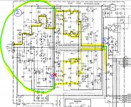
- Cut the VAS feed of channel 2 (the RED X mark)
- Short the VAS feed of channels 1 and 2 together (left green line) So that the VAS of channel 1 feeds both channel's drivers via the VBE loop.
- Jump (connect) the two outputs together and allow the 0.22ohm current sense resistors (ER ballast also) to let the 2 channels current share.
- The yellow lines just indicate the flow of the signal
- Will the inactive VBE in channel 2 interfere with the drive from the common VAS?
- Will the one VAS have enough current to feed both channels?
- Can I add another stage (given its seemingly lowish NFB, I am not very worried about unity gain, but I cannot be sure ) at the end, ie outputs to allow the VAS more of a buffer? ie Making the existing outputs as drivers and existing drivers become pre-drivers , in other words convert this to an output triple Darlington?
Thank you ALL for your help.
Attachments
Last edited:
Yes it does. It needs to be able to drive a 4 ohm load. Any self respecting amplifier should.If it is a Kenwood KM 206, does it really deserves such a butchering?
I have a specific use case for this amplifier. I am not interested in protection limited 130w/4e. I'd rather have 4 output devices not current limited doing something like 300w into 4 ohms, which is exactly what both channels combined are capable of. If you can stay on topic that would be helpful.The 'non-US' KM-206 version has a speaker impedance switch in the back to allow the rated power of 130W/channel @4ohm (150W @8Ohm).
Maybe you can try to emulate that in your version.
As you forgot to mention your ambition of 300W @4ohm in the original post, my suggestion was perfectly on topic.If you can stay on topic that would be helpful.
I would re-use only the case, transformer and heatsinks and replace the rest with a modern & proven design.
I would never connect decent speakers to a 'modded' amp like this. 🤣
I would never connect decent speakers to a 'modded' amp like this. 🤣
I have a Kenwood KM206 as well as its little brother KM106 that I bought for $50 each a few years back. They were meant for light duty home use. If you are trying to run a 4 ohm speaker hard the heat sinks are way too small. If you try to parallel just the output transistors you will run into thermal matching problems. You could try what the chip amp guys do and parallel the inputs and outputs. Use a small .1 or .2 ohm resistor on each output and connect them to the 4 ohm speaker. Mind you the offset voltage and gain of each channel must match exactly. Stability problems? who knows? With +/- 80 volt rails you are looking at possibly 45-50 volt RMS out put ie 600 watts with only 2 pairs of transistors! I have a power amp that will do 300+ watts at 4 ohms with +/-65 volt rails and 5 pairs of transistors per channel. It gets hot when driven hard and the heatsinks are 2x the size of the Kenwood's. Like Jacques said use the transformer and case and buy some boards or use as is.
Thank you Multisync. I think 300w 4e is very doable given that the 2 channels can do 150w 8e, so combined, 300w/4e into one channel is about what I'd expect them to do. The sinks, Transformers, i.e. everything is specced to do just that. I have thought about strapping both channels all the way to the input, but I suspect I will run into more problems with mismatched gain between the two channels, this is why I am leaning towards having one channel's input/VA stages, run the output stages of both. What do you think I am missing?
Last edited:
That it´s a kludge, that you are butchering an amp, that it probably opens more problems than it solves, etc.What do you think I am missing?
See how I stay on topic?
Don’t go paralleling more things than you need to. The more things you parallel the less likely it is to stay well behaved. To double the current capability you double up on the output transistors ONLY, and upgrade the drivers to higher current devices such as MJE1503x. And put bigger heat sinks on the drivers.
On +/-81 volt supplies, two pair of ANY output transistor really isn't enough. Three is better, 4 better still. SOA required is based on full voltage, because those repetitive peaks can go that high. The heat sink doesn’t cool down right away just because you’ve backed off on the volume and the supply has come back up - and you can still get short duration high dissipation conditions. What you have is a really woosy transformer which drops the DC output to +/-53V under heavy load. Probably some split bobbin piece of garbage wound with 22 gage wire, with about 30% reactance and almost as much resistance. That’s not the best way to get the most out of a set of output transistors.
On +/-81 volt supplies, two pair of ANY output transistor really isn't enough. Three is better, 4 better still. SOA required is based on full voltage, because those repetitive peaks can go that high. The heat sink doesn’t cool down right away just because you’ve backed off on the volume and the supply has come back up - and you can still get short duration high dissipation conditions. What you have is a really woosy transformer which drops the DC output to +/-53V under heavy load. Probably some split bobbin piece of garbage wound with 22 gage wire, with about 30% reactance and almost as much resistance. That’s not the best way to get the most out of a set of output transistors.
I wouldnt recommend paralleling. When it is done they tend to use 0.1% resistors to stop imbalances.
Bridging is safer. Just phase split signal into amps and bridge the outputs into 8 ohms.
Bridging is safer. Just phase split signal into amps and bridge the outputs into 8 ohms.
I agree with wg_ski and you should take his advice seriously (if you insist on doing this despite all people saying otherwise).To double the current capability you double up on the output transistors ONLY, and upgrade the drivers to higher current devices such as MJE1503x. And put bigger heat sinks on the drivers.
Q15 and Q17 will function at double current, double heat.
See attached, apply signal only to Left channel input.
If you have more and you can measure them, select and use transistors paired based on h21
Q15 with the same h21 as Q16
Q19 and Q20 and Q21 and Q22, all with the same h21
CP1 and CP2 resistors should have same measured value
this would help distribuite the current, load and heat equally between transistors.
Attachments

Last edited:
My feelings exactly.I wouldnt recommend paralleling. When it is done they tend to use 0.1% resistors to stop imbalances.
Bridging is safer. Just phase split signal into amps and bridge the outputs into 8 ohms.
Thank you so much for your input wg_ski. I agree with most of what you have said and want to address those. (ie Assuming my approach is to parallel the finals)Don’t go paralleling more things than you need to. The more things you parallel the less likely it is to stay well behaved. To double the current capability you double up on the output transistors ONLY, and upgrade the drivers to higher current devices such as MJE1503x. And put bigger heat sinks on the drivers.
On +/-81 volt supplies, two pair of ANY output transistor really isn't enough. Three is better, 4 better still. SOA required is based on full voltage, because those repetitive peaks can go that high. The heat sink doesn’t cool down right away just because you’ve backed off on the volume and the supply has come back up - and you can still get short duration high dissipation conditions. What you have is a really woosy transformer which drops the DC output to +/-53V under heavy load. Probably some split bobbin piece of garbage wound with 22 gage wire, with about 30% reactance and almost as much resistance. That’s not the best way to get the most out of a set of output transistors.
One caveat, will using just one set of drivers; not transfer the additional load on to the VAS? Can we mitigate this by adding an additional final output stage and using the existing outputs as drivers? I was planning to lift the existing outputs off the heatsink and install 4 MJ21193/94's in those slots as outputs. Use 0.22ER's for current sharing. If this worked and I liked the way it sounded, I'd even change out the woosy transformer. Looking for 5" 500va units if that happens. I didn't put in the additional details in the initial post as most people don't like reading long posts. At the end of the day, this amp will be running mids and tweeters.... don't see it being much abused.
Last edited:
TY Floriant, Lets assuming this is the way we are going. I am concerned the VAS will not be happy with double the current demand even if the drivers survive, thinking of adding 4 outputs as an additional stage to further isolate the VAS. There is the concern of unity gain at higher frequencies, which might lead to some filtering of the signal to stay below 50kHz or so....I agree with wg_ski and you should take his advice seriously (if you insist on doing this despite all people saying otherwise).
Q15 and Q17 will function at double current, double heat.
See attached, apply signal only to Left channel input.
If you have more and you can measure them, select and use transistors paired based on h21
Q15 with the same h21 as Q16
Q19 and Q20 and Q21 and Q22, all with the same h21
CP1 and CP2 resistors should have same measured value
this would help distribuite the current, load and heat equally between transistors.
To be on the safe side, you might want to run a LTspice simulation before blowing everything up.
- Home
- Amplifiers
- Solid State
- Help me join 2 channels together