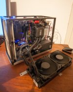
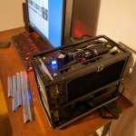
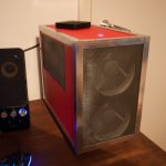
DIY magnetron sputtering machine.

I got tired of etching down materials with chemicals for diaphrams so I decided to DIY a sputtering machine.

After a couple afternoons of googling I've determined that a dual cathode unbalanced planar magnetron system may be what I need since they are used on larger substrates. I've thought about a quad magnetron but one step at a time.
1643768455126.png


I'll be custom fabricating the cathodes via a milling service and constructing a robust vacuum chamber but before I do that I'm going build a crude prototype first, using external magnets and applying the target materials to holes on the outside of a custom diy acrylic vacuum chamber.

The vacuum will seal the target material to the chamber during use.

I'm going to use some used ion pumps from ebay to provide the vacuum.

r/homechemistry - Developing a DIY dual cathode unbalanced magnetron sputtering system. Could use some advice.
The dimensions are a bit skewed in that picture but you get the idea.

I think the need to get watercooling on the cathodes may be required so I might need to mill some out before attempting this.

One big question I have hanging over my head is what the dimensions of the target material should be.

I haven't been able to find much literature on this, only that the target should be larger than the substrate area.

Since my substrate is rectangular in shape, naturally I am considering making the target material a rectangular block, but rectangular cathodes are only used in conveyer belt type sputtering systems and there are vague mutterings that circular cathodes may provide a more uniform deposition on to the substrate, but he information I've found is unclear.

There's also the fact that most substrates used in sputtering are circular in nature and none of the literature may apply to rectangular substrates.

I'm currently planning on making the target material twice as wide and long as the substrate as it intuitively seems like it would be the most efficient and linear way to deposit the material.

I'm wondering if anyone here is knowledgeable enough about this subject to tell me if this is a good/bad idea and why.

My other big question is, why does the magnetic structire always have a N/S/N configuration on the cathode? Why not a longer N/S configuration? Or why not a N/S/N/S/N/S configuration?
The material sputtters off at the field between the N and S poles, so it makes sense to have either one large field or many small ones so avoid the typical 'racetrack' utilization pattern on the material.
Is it more important to keep the fields close to the target material or can the field bend outward a bit?

Not a whole lot of literature I can find on this stuff.

I would love to hear any advice on construction and or any other details.
I'm going to need all the help I can get to do this right without making costly mistakes.

Much appreciated if anyone can help.
Matching preamps with amps

I currently have a moreplay preamp from bottlehead with the ACA 1.8. I would like to experiment with another First Watt amp build but I’m not sure how important it is to pick the right combination of preamp and amp. Are there preamp / amp combinations that should be avoided in general and specifically with the moreplay?

My listening experiences are extremely limited. I’m enjoying the learning and building process and having something that sounds good is a nice bonus.

Inductors and capacitors in a portable speaker

I'm in the process of building an inexpensive portable speaker and I had a couple questions as I haven't really had any experience with passive crossovers. This speaker will be a two way, and I'll obviously have a high pass on the tweeter but I don't want the woofer to run fullrange either.

1. Will using an inductor with a woofer similarly to how I would use a capacitor with a tweeter give me a 6 db/ octave slope? How would I go about calculating the inductor value? I know nothing about inductors.

2. With an inductor, could I also use a capacitor as a "bass blocker" for my woofer while also using the inductor as a low pass filter? Or will the two interfere?

Help designing cabinet for Tectonic TEBM65C20F-8

Hello, I'm new to speaker design and would like to start with with a simple full range driver.

Could someone help me work out the optimal cabinet and port dimensions to suit this driver?

http://www.tectonicelements.com/wp-content/uploads/2014/04/TEL-DS-TEBM65C20F-8.pdf

Would a sheet of 1/4" MDF and length of PVC drain pipe be suitable?

thanks

Hearing Acuity

With all due respect, I really don't want to offend you in any way, please don't get me wrong on that but with a 52-year audio career, you must be very well aware of the fact that your own ears can not be fully trusted anymore. (the same counts for everyone here over 60)
Yes, it's well documented that hearing acuity changes with age, with a loss in overall sensitivity and a more pronounced loss of high frequencies.
As frustrating as it might be, that is the truth. The angle at which you are able to locate sounds has severely widened from a couple of degrees in your 20's to 30 degrees or more now. Older people do hear differently and do have a different perception of sound, it's impossible you are not aware of that. It's good to know this information, it puts your post into perspective.
Thanks, but two things: 1, if you have documentation about the ability to locate being a wider angle with age, please share. I would find that interesting.

2. My posts are not based on my own hearing. In research the last thing you want to do is base a conclusion only on your personal perceptions of in test. In other words, you can't be the only tester. It takes a lot of expensive testing with a statistically significant number of testers and a significant number of trials, and scroupulous double-blind administration to be able to compile enough data to obtain good results resolution.

The seminal paper on this is "High-Resolution Subjective Testing Using a Double-Blind Comparator" by David L. Clark, J-AES, May 1, 1982. David is sadly gone now, but I still own and use his comparator system.

The fact that hearing in older people degrades in any aspect does not put my posts into any particular perspective. But if someone else claims to have performed any sort of testing, controlled or not, and they are the only tester, you have to pretty much chalk the results up to opinion, because there is bias involved, and far too little actual data.

  • Poll Poll
i'm working on my graduation project and I face the subwoofer box calculation obstacle...?


hello, guys
I'm working on my graduation project and I face the subwoofer box obstacle, I'm a computer science engineer student but my project need this so, I need help with how to calculate the subwoofer box and which the best design is more efficient for my project criteria :
  • the speaker should be inside the box
  • speaker diameter: between 16 - 17 cm
  • max box size : Length = Width = Height = 20 cm
  • min decibel: 90
design should be like this
Screenshot 2022-02-02 195307.jpg
Screenshot 2022-02-02 195353.jpg


or like this

9a8fb8a5-4035-40fd-9064-06ac8134922f.jpg
211f020a-a4d4-4871-a150-2f3b65b1d5a5.jpg


-------------------------------------------------------------------

I have this amplifier is will work for me ?

Pyle PLMRMP1A
  • 2 x 100 Watts RMS at 4 Ohms
  • 2 x 200 Watts Max at 4 Ohms
  • 2 x 300 Watts RMS at 2 Ohms
  • Stereo to RCA Adapter
  • Fuse: 10A
  • RCA Line Input
  • T.H.D: <0.05%
  • Soft Turn On/Off
  • S/N Ratio: >95dB
  • Anti-Thump Turn-On
  • 2 Ohms Stereo Stable
  • Power Protection Circuitry
  • Channel Separation: >65dB
  • Volume Gain Remote Control
  • Electronic Crossover Network
  • Remote Control for Volume Gain
  • Adjustable High Low-Level Inputs
  • Frequency Response: 10Hz - 40kHz
  • Dimensions: 4.13'' L x 3.35'' W x 1.38'' H
THANK YOU SO MUCH !!!

Seas P17Re coax crossover evaluation

Got hold of some OEM seas Coax. Woofer is similar to this: http://www.seas.no/images/stories/vintage/pdfdataheet/h0653_p17rextvf.pdf
but in 4 ohms and with a metal dome instead. Built a 10 liter bassreflex tuned to 50 hz.

I am quite satisfied with how they sound, but still on some types of music, I feel something is "strange"

How does this look to those of you who know (I am just messing around... 🙂 )


Seash905crossover.jpg

Black is with tweeter inverse polarity
SeasH905freq.jpg


SeasH905imp.jpg


Is there something strange with this impedance plot?

FS: Sony TA-4650 Vfet ( baby Vfet)

For sale, Sony’s baby Vfet the TA-4650 Integrated amplifier . The unit has been freshened up by the previous owner. The killer diodes were replaced to protect the precious and rare Vfet transistors which are no longer produced. Some parts were upgraded with black gates, Riken, nichicon muse, it is clean inside and out and is in good condition. Can be used just as a preamp or just an amp. 35 watts a channel into 8 ohms. Vfets that are transistors that have similar characteristics to the triode tube. im asking $485 plus shipping . I will only ship to the lower 48 states only. The unit will be packed well And double boxed.
F0A5190D-D66D-4E67-B938-ADC3B0D18811.jpeg

FA466785-5FE2-4E9E-8C87-C9D157BDA7DA.jpeg

Using mains transformer as output transformer

Hello,

I'm thinking how well would a toroidal mains transformer work as an output transformer. You may need to modify the secondary winding to get the correct transform ratio but there should be not much problems in that because in toroid the secondary is on top and extra windings easy to remove. (I've modified toroid earlier also but for different purpose)

So the starting point could be for example 230V/12V 120VA toroid which are easy to find and quite cheap too.

How will the distortion level be in these kind of toroids? The power rating should be enough for <10W output, right?

How about bandwidth? I would guess that because the big and heavy toroid is initially designed for 50Hz, it could support low frequencies quite ok? I don't know what will happen at 20kHz though?

Which one would be better actually, a toroid or 'square' iron core mains tranformer for this purpose?

Please share your experience 🙂


- Elias

Need help finding mid driver for my horn speakers

Hi everyone, I hope y’all are doing well. I have avant-garde acoustic Unos from 1999 and I recently broke the membrane of them. It’s an easy fix of glueing them back together but then I thought I would change the driver all in all. The stock drivers sound very cold and are way too fatiguing, the detail is insane but just not enjoyable for more than 1 hour so I’m happy to swap them
0DBFC7BF-457A-4C17-AF92-1EA95465468B.jpeg

Does anyone have any mid range driver recommendations for horns? Budget is 1.5k usd for both drivers
they are 12cm drivers 8ohms

I’m particularly new and this would be my version of diy 🙂

Thanks to anyone that can help me

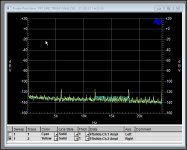
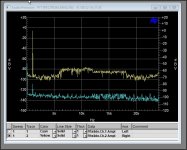
Audio Precision system 1 FFT sweep high noise floor

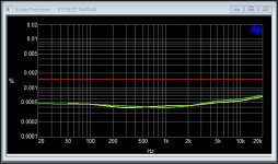
I have an AP System One Dual Domain. It has been used for spot measurements and THD sweeps and is fine. Passes all self tests (RED TICK BOX) very well indeed.
I just purchased the amazing USB interface from s1usb.com which makes the combination so good it prompted me to look at using the SYS322A for something important.
I needed a FFT sweep and started of with sweep of the internal gen.
I spotted some spurs on Channel B input at 6kHz, 12kHz, 18kHz which I dont recall.
But more worrying is that connecting a source, either AP internal Gen or expernal gen from say R&SUPV the presence of siganal lifts the noise floor way above that for the source or the analyser - by some 25 db or so.
More concering though is that there is a step increase in noise of almost 20dB afrom 6kHz to 18kHz - too much of a coincidence given the spurs maybe?
Dropping the input level by 10dB all the problems drop by 10dB as well - odd.
Similar behaviour on either CH1 or CH2 although the spurs are only really visible on CH2. And CH2 the step change in noise floor is slightly less pronounced.
Any thoughts?
Could easily be driver error - but if it is real hardware trouble I am really not sure where to start digging as the input amps etc must be all good to work OK for spot or swept THD measurements.
Where does 6kHz come into play??
This AP does not have the leaky brown electrolytics and all is clean and tidy inside so far as I can see.

Alan

Attachments

  • ScreenHunter 3798.jpg
    ScreenHunter 3798.jpg
    71.7 KB · Views: 140
  • ScreenHunter 3799.jpg
    ScreenHunter 3799.jpg
    82.5 KB · Views: 147
  • ScreenHunter 3800.jpg
    ScreenHunter 3800.jpg
    77.4 KB · Views: 160
  • ScreenHunter 3803.jpg
    ScreenHunter 3803.jpg
    58.2 KB · Views: 137

parasound D/AS 1000 II question

Hi!

I have a qustion regarding bias setting for this amp. Both channels were blown, managed to fix that, but dont know how much bias would be reasonable. Curently runnig at 100mA/device but runnig quite hot (cant hold hand on heatsinks). Schematic is for D/AS 1000, mine is mark 2, should be the same except different parts used. Original output devices were 1 pair 2sa1302/2sc3281, 2 pairs 2sa1215/2sc2921, which i replaced with 2sa1943/2sc5200 & 2sa1295/2sc3264.

Thanks

some pics:

An externally hosted image should be here but it was not working when we last tested it.


An externally hosted image should be here but it was not working when we last tested it.


An externally hosted image should be here but it was not working when we last tested it.


An externally hosted image should be here but it was not working when we last tested it.


An externally hosted image should be here but it was not working when we last tested it.

My attempts at a design of a 3 stage amplifier

First, I will admit to myself that these attempts may prove useless.

After so much head scratching, I inputted the input stage of what I think the input stage should look like. I am using the CAD hog named KiCad. It is a huge piece of software that probably requires one to buy a book to even start using it. As you can see, I haven't figured out how I can neatly display the various texual descriptions displayed next to components.

The attachment is the first stage as I am imagining it. I will use a cascode to isolate the input from the high voltage of the power supply. I am aiming to first make the input stage, test it to make sure it meets its required standard and then proceed to the VAS. The power stage is already built as it was part of a large public address amplifier that failed. I will usethe PA amplifier's chassis, power supply and power stage and redesign the pre-driver stages.

You may deem me mad, but sometimes being mad may be the only adventurous and successful route.

I am posting both for your comments (criticism) and hints about how I can use KiCad to get a better looking schematic and for improvements that I can make to the input stage.

Thanks to all those who made this website a reality and to those who will contritbute to this thread.

Attachments

Power supply for tda7293 mono amp build

I recently purchased 2 tda7293 boards and was wanting to build 2 mono block amplifiers with them. I also got two dual power rectifier boards also. Each one is 25v with four 3300uf caps on them with a dual input voltage at 9-17v.new to the amp building thing and been looking at the threads related to my question but haven’t found any solid info to help so my question is how should I go about and what would be the most simple way of powering each one. A 120v transformer mabye? The speakers I have run on either 4-8ohm loads and at 75watts per speaker. I’m also not interested in maximum volume or power. Just wanna be able power them decently with hopes of a good sound with good volume if all goes well. I was thinking maybe making an external power supply or would it be better to put the power supply with amp also in a chassis? Any help in leading me the way would be so appreciated :scratch1:

Boss BF-1 Schematic and troubleshooting

Hello all,

So, I had a working Boss BF-1 and my bandmate had accidentally plugged 18V into it for about 5min until I realized something sounded off.

Now, when the pedal is disengaged/bypassed (but not true bypass) it has a loud noise that runs through the signal. Yet, when engaged it seems to be working okay. The same noise is there, but it is buried underneath the effect.

I tried emailing Roland to get a schematic to help me trouble shoot potential problems. They denied me and referred me to their certified repair places. I called a couple of them trying to see if they could share the schematic, with no luck.

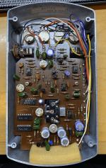
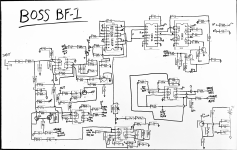
So, I went to work reverse engineering the PCB (photo attached). Since it was only one layer of traces, it wasn't too bad to draw it out. I first drew it out on a white board (photo attached) and then made a better looking schematic on KiCad (pdf attached).

I am mostly creating this thread to share the schematic for others since I was unable to find one online. But I want to be clear that there could be error in this. I am not saying this is 100% the Boss BF-1 schematic.
I made sure to look up all the datasheets (all attached) of the active components and tried to decipher some of the ceramic capacitor markings the best I could.
There is room for error in this schematic, but I really did try my best.

I also created this thread to get some help because I would rather not go and replace all these components if I do not have to.

So, here is what I have found so far and where I am:
  • I noticed the electrolytic caps where max voltage rating of 16V. I took em out, tested them all and replaced all but a few (C10 & C21, they were good). I replaced the others with Nichicon caps that matched the previous caps almost exactly (capacitance, rated voltage, temp rating, and diameter). This did not fix the noise, but it did make the effect sound much more lush and full which is nice.
  • I have looked through all the datasheets and, to me, it seems like all the active components can handle 18V, yet I do not know about the signal strength increase due to 18V that could have maybe broken a component. The only active components that could have hit the hardest is the Reticon SAD1024 since the datasheet states the absolute max voltage it can take is 18V. But that chip is used in the effect line for delays and the effect sounds just fine. So, I'm at a loss there.
  • The Zener diode (D6) is fine. I have yet to take out the other diode to see what they are and if they work.
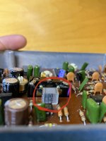
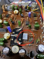
  • C33 is a puzzle to me. It is also the (?) on the whiteboard schematic. I have attached a picture of it. Im not completely sure what it is, but it does say 1uF on it. If anyone has any clue, please let me know. I have tried to find it online to identify what it is exactly.


Alright, thats all I got! If anyone has any idea on what to look for or see's any potential problem, please let me know!

Attachments

RIAA phono stage testing: Headroom / overload

Hi all-

I’ve been working on several phono stages lately and have discovered a nice headroom test that capitalizes on how the Quantasylum QA401/QA402 analyzers work.

They both use a flat drive signal to excite the DUT, and subtract out the RIAA curve from the received data. Because RIAA has 40dB more gain in the bass than the treble, a phono stage can be interrogated to reveal its overload structure at low frequencies, where a flat drive signal, and a real world turntable, will always overload first.

Here is the exact same preamp before and after changing the opamp rails from ±14V to ±17V. This proves the phono stage overload got a lot better! Very cool these boxes can do this.

Input overload Unit 1 before mods.png

Input overload Unit 1 post mods.png

HEXFETS matching for drivers

While lateral MOSFETs make the best and simplest drivers for large amps, HEXFETS (now Vishay), are often favored for hobby use and smaller amps because of cost.
The issue with choosing HEXFETS is that the listed complementary devices are with regards to voltage and current ratings, and not for matching characteristics in linear use.
I was in charge of some R&D on this issue some time ago, at the time the results were proprietary. Surprising performance was obtained from common topologies by matching on resistance , gate capacitance, and transfer admittance as well as possible for a given minimum voltage and current requirement. Slew rate and distortion improved vastly over triple Darlington designs, especially when a dual differential front end was used. We used a bootstrapped "bias ladder" to obtain near rail-to-rail swing. Higher on resistance and lower transfer admittance tended to be the most linear. The important thing about MOSFETs is that as a voltage controlled device, it breaks the chain of current demand from propagating back to the VAS. That goes a long way towards negating distortion caused by general mismatch of base current draw by so called complementary output devices. That allows use of less open loop gain, and simpler front end design for a more open natural sound. Extensive MIT research in the 80s showed that the complex waveforms of music did not play well (pun) with long rates of loop closure associated with cascaded differentials and other complex methods used to bring down THD. These MOSFET pairs are all easily driven to high slew rates by any VAS with 10ma design current. If there is interest, I have more material on the HEXFET driver research.

Here are those pairs : 2A 2.5 OHM 1S class: IRF614 , IRF9610 , 4A 1 OHM 1S class: IRF624 , IRF9620 , 6A 1 OHM 3S class : IRF730 , IRF9630

Attachments

NCore ICEpower Other Class D with Electrostatics

I have tried quite a few Class D amps on my Electrostatics over the past few years - Quad ESL-63, Acoustat 2+2, 1+1, Model 3, Spectra 22, and Spectra 11, Sanders Model 10C, Martin Logan CLS IIz (I may be forgetting a couple more).

Only the ICEPower 1000ASP and 500ASP (have not yet tried the 250ASP) had no issues. Although I do remember a night where my Acoustat 2+2 at fairly high levels caused one of my 1000ASP monoblocks to shut down, but after power cycling and reducing volume, it was fine again...

The Hypex UCD400Hxr and NC400 both fluttered and shut down after about 12 - 15 minutes on the Acoustats and CLS and CLSIIz at normal volume. Also tried the Emerald Physics 100.2SE (TDA8954 Class D amp) and had similar issues. All were power cycled and were fine again...

Surprisingly, the ESL-63 were ok with all amps but the Emerald Physics, but I did not push it.

Its understood that Class D amps have issues with the Capacitive loads an Electrostatic Speaker presents to it...

BTW - never had a Class A / AB amp shutdown on them...

So, has anyone successfully driven ESL speakers with NCore amps, UCD400Hxr, or other Class D? Like I said, the ESL-63 seems to be an easier load than the nasty Acoustat 1+1 and CLS...

None of these amps had any issues driving my Magnepan 3.5r to high-ish volume...

DIY bluetooth speaker adapter powered showing 30% battery only ??

Hi

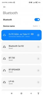
I recently completed another project but run into another funny problem. This portable bluetooth speaker is DC adapter powered and the supply to the bluetooth is through a 7805 regulator then passes through a B0505S power isolater. Now whenever the bluetooth is connected via my smartphone it will show only 30% battery instead of 100% battery using my previous method separated power transformer method. The B0505S i've build didnt use any of the input and output filter caps ... just direct input and output connected to the Bluetooth module ... Any idea what is causing it? Thanks

Attachments

  • 272327923_3157297247841062_4539696449583458154_n.jpg
    272327923_3157297247841062_4539696449583458154_n.jpg
    95.8 KB · Views: 101
  • 272843003_456259246151874_280669938134246645_n.jpg
    272843003_456259246151874_280669938134246645_n.jpg
    28.5 KB · Views: 100
  • download.jpg
    download.jpg
    7.9 KB · Views: 93

What kind of amplifier for my planars?

Good morning everyone ,
I would like to get your opinion on a speaker and amplifier pairing.
I have two Yankee audio planar speakers by Eng John Taylor have a measured resistance at the ends of the speaker terminals of 2.7 R.
A class A amplifier of about 100 watts is recommended.
The planar speakers have no crossover and the power amps are directly connected to the speaker terminals.
I have experience with amps with lateral mosfets "sk135 and 2sj50 and now with Profusion replacements.
Any suggestions on amp or design ?
Mosfets or transistors ?
The important thing , given the quality of the speakers, that it is up to the task and of high quality.
Maybe the designs of Mr. Nelson Pass?
Thanks in advance for your comments.
Giubos

Attachments

  • IMG_4413.jpeg
    IMG_4413.jpeg
    370.4 KB · Views: 92

  • Locked
Resolved - Bug Squashed Paid membership level signified with multiple stars – really not elegant solution

I just upgraded my membership and got two stars. Really don’t like how it looks and would downgrade my membership, if I could, solely for that reason. I notice that some members have 3 stars and I suspect that much higher number is possible. When they make single line post, their avatar + vertically aligned stars make tall post with a lot of blank space.

It would be better to use only one star with different color for membership level.

Antek 15T950’s as OPT

I’ve got a question for the power-crazy folks among us, who use power trafos for OPTs. Or perhaps someone just stuck up against impedance flexibility. First a little background and the motivation here. The ultimate goal is building a “1000 watt” (per channel!) amp using 26LW6 tubes driving Antek 15T950’s as OPTs, which is in the process of gathering the parts and working out details. If it takes 15 years I don’t care. At the moment, I’m doing the “intermediate” step of building one a little smaller but the same general idea. Using up to 8 21LG6’s to drive an Antek 8T800. The best configuration is to use 600 V B+ (under load) with 8 ohms load, and should give almost 350 watts. The speakers won’t always be 8 ohms - that pair hasn’t even been constructed yet - it’s on the to do list and waiting on a recone kit to boot. The BIG one will only be used with 4 ohms so impedance flexibility is not an issue. But impedance flexibility would be nice here. So what to do with a fixed Z OPT? My thought is to lower B+ to 450 for 4 ohm use. Are there any gotchas that make this impractical? Different optimum screen voltage, but that will come from a regulator anyway and could be made switchable. Sweep tubes have enough current capability on paper anyway. How likely would it be to need rebalancing of the bias (to keep DC out of the core) when changing the B+, or will one adjustment for the group be enough once it’s initially trimmed?Has anyone done this? I already have the power trafo solution on hand for “8 ohm only” operation, but have a couple identical of donor cores that I could wind up with the proper taps to provide both B+’s AND the lower screen voltage for the regulator. Is it worth making these power trafos (would need to buy a roll of wire of the proper gauge so all the winding fits - I’m not sure a #19 will fit and 22 is undersized). Or is it a fools errand and should just use what I have on hand for and design for 8 ohms only? I will during initial phases.

Soldering from bottom of pcb

I’m wondering if there’s any difference between soldering from the top or bottom of a pcb? Last time I soldered from the top and created a real mess of flux residue. Also, this pcb is fairly tightly packed with components so cleaning thoroughly afterwards is difficult. I’m picky and want to leave a clean pcb. If I trim the thru hole leads flush cleaning the bottom seems like it would be much easier.
What do you think?

Crown XLS 1502 or 2502?

Hi

I've a pair of B&W 683S2 and are looking for stronger amp to drive them. I've read alot of good stuff about people using the CROWN amps XLS series in their home theater.

What would be the best match for my 683S2:

SPEAKER SPECIFICATIONS:
• Sensitivity: 89dB/2.83V/m.
• Harmonic distortion (second and third harmonics, 90dB, 1m): <1.0%, 95Hz–22kHz; <0.5%, 120Hz–20kHz.
• Impedance: 8 ohms nominal, 3 ohms minimum.
• Recommended amplification: 25–200W into 8 ohms on unclipped program.

► AMPLIFIER OPTION 1: CROWN XLS 1502
• Class D
• Power rating: 2x 775 W/ 2 Ohm, 2x 525 Watt/ 4 Ohm, 2x 300 W/ 8 Ohm, bridged 1x 1550 W/ 4 Ohm, bridged 1x 1050 W/ 8 Ohm
• 24 dB Linkwitz Riley crossover
• Input sensitivity 1.4 or 0.775 V

► AMPLIFIER OPTION 2: CROWN XLS 2502
• Class D
• Power: 2x 1200 W / 2 Ohm, 2x 775 W / 4 Ohm, 2x 440 W / 8 Ohm, bridged 1x 2400 W / 4 Ohm, bridged 1x 1550 W / 8 Ohm
• 24 dB Linkwitz-Riley crossover
• Input sensitivity 1.4 or 0,775 V

Both amps are specified to go well above the recommendation 200W. Will the 2x440W do a better jobb than 2x300W? Is it worth the 200$ extra?
I'm not technical at all.

jfet clipping

Hello everyone out there, I am playing around with fets and need some help. When the circuit below clips on the positive halve of the output, it clips rather sharp:
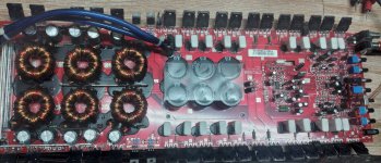
1643734584425.png

1643734631691.png


Now, when I substitute part of the source resistance with a couple of schottky (or germanium) diodes, the sharp edges get smoothed:


1643734882578.png

1643734919083.png


The question is, what exactly is happening here?

Looking forward to your replies, and sorry for the rather large pictures.

Attachments

  • 1643734162355.png
    1643734162355.png
    2.7 KB · Views: 189

A pre for the TU-8600?

Aside from more inputs, what benefits would a preamp confer upon the already amazing 8600? I know I could buy one and find out, but I’m hoping to hear from those who have tried adding a preamp and observed either an improvement or a degradation in sound quality. I have a decware zen switch box in order, so the input problem will be solved. But would an active pre add or detract from a pure 8600? If it depends, what should I look for in a pre that will mate well? So far my philosophy has been less is more - just get as many components out of the way as possible. But maybe the 8600 is really designed to be fed by a line stage preamp.

Sources are Lehman audio Black Box phono pre and a Luxman DA-06 DAC. Thanks in advance.
Adding Volume Remote control - how to get 9V?

I built the Korg preamp in my own chassis and wanted to add remote volume control to it.
I saw the Alps version from Bent Audio and wanted to incorporate it, but want to know the best way to get 9V DC to power the device.

I currently have a CapMX power supply and adjusted the voltage to 24V to run the Korg. The website for the Bent Audio device says between 8 and 24V dc but then the manual states 8 to 18V. Regardless, I would like to know the best way to get 9V off of my power supply?

http://www.bentaudio.com/index2.html
5C1182AC-55F2-43AF-9ED7-284B990593B7.jpeg

AD1865 NOS output config

Hello,

I appreciate you guys help on my secondary DAC project. In my main DAC, I use a resistor I/V after the DAC on the legs of LL1527XL interstage transformers and followed by triode buffer. Now, on this "secondary" DAC, I want to achieve the maximum I can for listening to music on headphone (HD800). I've dropped the TPA6120 because I found my "old" modified CK2III is better for my taste. Now, with the JLSounds input you suggested, the DAC works well, but I'm struggling with the output. First, I've tried with an I/V resistor and parallel cap on the headphone amp input. It actually works very well, but, somehow cuts off the top. Even if I remove the 10n "low pass filter" cap it still cuts the very top. I need a buffer stage with low pass filter, but, without transformer and tubes. Should I just put an OPA627 with 47pF in the feedback like here ? https://www.diyaudio.com/community/threads/easydac-nos-r-2r-ad1862-dac-headphone-amp.312486/ , or, do you have other suggestion? My problem is, I do not like filters in feedback. Long time ago when I've used opamp based RIAAs, I've much preferred filters in the normal path, not in feedback (like the CODD RIAA, do you guys remember? 🙂 , also, I'm not sure about opamps. I understand nowdays with carefully selected opamps I can get better results than with bunch of transistors even I spend a day pairing them. So, OK, opamp, but really with feedback filtering?

What do you guys suggest?

Thanks a lot !!!!!
JG

(This subject is very important for me now. I'm in a situation that 5 days a week only this can feed me with music :-( and I'm starving for music, really. I know it is my fault, I sit down with my really excellent commercial audio interface and headphone, after 15 min the "ssss" hurts on vocals, the base is soft, weak and too much, the stage is foggy ... I know the DAC is the weak point in my chain. When I connect the headphone amp after my big DAC at home, I feel like "this is it", that is what I want. Or close. But these solutions I have now are pretty far. )

Coupling capacitor calculation with stepped attenuator input impedance plus amplifier input impedance

EDIT: I failed at reading comprehension. rayma smacked me on the head and got me back on course. No further reading on your part is require 🙂

I'm building a GlassWare Aikido line stage and am using a GlassWare Attn-2 stepped attenuator board for volume control. I selected my output coupling capacitor values using the formula 159155/C/R, based on an R value of 47k, which is the input impedance of my amplifier.

The manual for the Attn-2 says that it will present an input impedance of 20k to the line stage, and describes how this would cause poor interactions with an older tube line stage that expected a 500k load.

My question is, when using this attenuator, does the input impedance that the line stage sees change to 20k? Does it become the sum of the attenuator impedance and the amplifier impedance? Or something else entirely?

AK4458 multichannel DAC with I2S input

Hi all,

I have made this topic for my upcoming project, AK4458 multichannel DAC. There are not too much multichannel DACs on the market, but I need it to drive my active loudspeaker system correctly.

This chip is reasonably priced and has a simple layout (only 48pin) but still have good enough parameters to build an outstanding DAC I think....

I you have any advice, experience, please share it! Thanks...!

/ alternative could be the ES9016 but ESS does NOT support public designs and the costs of a chip incl. taxes and shipping is horrible! /

IcePower 500a failure

Hey guys!

I recently built a 4 channel amp using; 2 x IcePower 200ASC + 200AC modules (Mids/highs) and 2 x Icepower 500asp + 500a (lows) all running off of a Minidsp 2x4..

Im driving this(500a) board directly from the 500ASP module and I have 2 x 100v 3300 caps between the modules.. (icepower notes adding capacitance between modules for extra power duration).. I'm running these modules at ~2.6 ohms (3 - 8ohm woofer in parallel) and the data sheet states min. of 2 ohms.. Also.. both are mounted on heatsinks AND fan cooled!

So.. the issue...

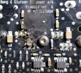
Few weeks ago.. The 500a module failed and blew off a ceramic cap.. Im wonder what would have caused this?? Bad cap?? Bad luck?? 😏
I'm assuming this is something of a rare event and isnt something i did wrong.. (which is what im hoping!! lol )

When the amp module failed i was NOT pulling any power.. was just watching TV so probably at best.. a few milliwatts of power being pulled from the modules..

THANKFULLY the main module (500asp) was not harmed at all and I have since received a replacement 500a under warranty!

------
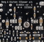
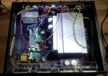
Added pics of the failed board, a "good" board and the inside of my amp build!

Attachments

  • iceamp blow.jpg
    iceamp blow.jpg
    208.8 KB · Views: 400
  • iceamp good.jpg
    iceamp good.jpg
    31.9 KB · Views: 361
  • 4ch amp inside.jpg
    4ch amp inside.jpg
    160.7 KB · Views: 751

Cheapest / Most basic upgrade. Cabinet cross brace and light fill. Request for comment.

Hello all.
I am working with a set of Yamaha NS 6390 / 6490 bookshelves. As these speakers are going to be built into a zenith allegro console. (I am just jamming them in the cavity of the console, box and all.) I am not going to spend much time with the speakers until I rebuild the complete cabinetry of the console.
That said I intend to place a 2" x 2" dense Oak cross brace side to side, and a 2" thick piece of paper backed insulation on the inside rear panel.
Any other low budget mods having to do with fill or bracing that I should do while the woofers are out of the cabs ?


Jeremy

PSU design/upgrade for a Cambridge Audio S700 Isomagic DAC

Hi Guys,

I'm trying to resurrect my old Cambridge Audio Dac, the PSU has seen better days and it's a lovely DAC so I thought I would make a new one for it. I was hoping someone could look over my calculations to see if this would work?

For those that don't know, the DAC uses a power brick with a umbilical cord. The original PSU uses a small 15v ferrite core transformer (rated at about 25VA), with 2200uf filter caps, going through a diode bridge and then along the umbilical cord where each section of the DAC has it's own regulator (12v, -12 or 5v, about 12 in total).

Where my potential troubles start is that I would like to use a 12v * 2 toroidal transformer rated at 50VA total, I believe I can *just* get away with this, but wanted to make sure, this is what I have planned:

12v * 2 going through MUR820s (due to their voltage drop of about 0.6v at 1A)
(12v x 1.414) - 0.6v = 16.35v, factoring in the 13% regulation and with no load it will reach about 18.5v. I will be using 3300uF Pan FC caps and as each line can supply 2A and the DAC uses more like 1A i'm assuming I will be able to get a bit higher voltage than the 16.35.

I would then like to use regulators in the PSU, I want to use LM338 series, I know they are overkill with them being 5A, but they seem to have one of the lowest dropout voltages at this power level, with the datasheet showing about 1.75v at 1A (and I have quite a few spare). I was hoping to set the output voltage at about 14.5-15v, maybe nearer 14.5 as 14.5+1.75 is very close to 16.35.

On the DAC itself, the main regulators in question are L7812s, the datasheet for those says a minimum voltage of 14.5v is required, the datasheet graphs show at 1A you can get away with 14.2v.

Ideally I would use a 15v transformer, but I have so many of them I would like to use them up before ordering yet even more. Is anyone else able to tell me if these margins are acceptable?

I was also thinking of changing the main regulators on the DAC from L7812/7912 to something like TL780-12, as the worst case regulation figures (min/max) seem to be about 5x better, or is that a bit overkill?

Many thanks in advance for any advice, hopefully my messy calculations make sense.
Cheers

Soundstream TR500/4

Is there a schematic available for this series of Soundstream amps? This amp came in with a few problems which I've repaired; but Left Rear channel is not passing audio only extremely quietly. Seems mute is engaged just for that one channel.

This amp is using J108. 14 of them. There are 10 near the preamp and one for each channel. All but the LR channel has audio on that JFet.

LR Audio is passing through several opamps and the controls seem to be working OK on the preamp.

For Sale Aleph J boards + mosfet kit

Partially populated Aleph J boards + mosfet kit. The mosfet kit does NOT include the 4 x 2sj74.

50$us for the whole thing.

Free shipping to canada, 15$ to the US. PayPal only.

Attachments

  • AEF7E4D8-6811-4696-A06F-A563872C1FB9.jpeg
    AEF7E4D8-6811-4696-A06F-A563872C1FB9.jpeg
    354.8 KB · Views: 220
  • EF3E5A06-5545-4F56-993A-19F0E4EA9470.jpeg
    EF3E5A06-5545-4F56-993A-19F0E4EA9470.jpeg
    452.9 KB · Views: 236
  • 2905A7DC-6866-4BCA-AC85-2DD693FED669.jpeg
    2905A7DC-6866-4BCA-AC85-2DD693FED669.jpeg
    353.7 KB · Views: 226

Subwoofer crossover

Hello, I would like some help in regards to knowing what the crossover should be for my pa speaker set up. I will be running 2 EV zlx 15bt as tops and 2 Mackie Thump 18s as subs. If I use the built in cross over on the mackies then it would be at 140hz, which seems a little high to me. The EVs allow me to specify a crossover point. We plan on running keys, guitar, bass, and vocals though the system. What do you guys recommend?

Thanks

Tool search: *Really* small circlip pliers?

Hi all-

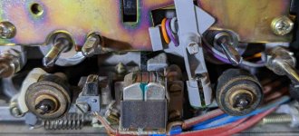
So I'm restoring a couple classic cassette decks, and in order to get the pinch rollers off I need darn near microscopic circlip pliers. Attached are a couple photos. Those shafts are about 2mm diameter...

I went to McMaster and even they don't have anything small enough. Any hints to where I can find a circlip tool to deal with this? Thanks, as always.

Attachments

  • Revox B710 MkII b.jpg
    Revox B710 MkII b.jpg
    319.5 KB · Views: 183
  • Studer A721 b.jpg
    Studer A721 b.jpg
    167.7 KB · Views: 177

Driver search program?

I have been looking for a driver that will cover roughly 100Hz down that will match or better a mid's 95dB sensitivity. I don't use Home Theater and listen in a fairly small space at levels you can easily talk over. To look , I got BassBox 6 Pro as they advertise a large database , which it does have, and they have a function where you can bracket Vb and F3 and search drivers that will suit. Very nice. Except that when I put in a broad range of 100 to 200 litres with F3 = 20 to 35Hz, and check for only available drivers , I get 16 hits , almost all of which the latest data for was 2001 and are no longer available.

My question is broadly, is there another program that you can do a similar thing with that has a more up to date data base? I looked at Vituix Cad and you can scroll through the drivers very nicely with instant graphic results (Very Nice!) but it adjusts the box for every driver and I don't see a way to lock it.

Alternatively , when you know what you want but not the driver to do it, what do you do to streamline your search. It seems that the vast majority of builders use an eq program to take care of any FR issues which I'm not open to doing and there are a heck of a lot of drivers out there to go through.

Thanks very much.

Faulty zenon driver board?

Got a 3500.1 here, blew up 8 of 16 irfp064's while at low volume so I'm attempting to repair it.

First thing I did before proceeding with the oscope was remove all ps fets,gate resistors,pulldown resistors and npn/pnp drivers, this amp is old so I'm going to replace those regardless.

I noticed that only half of the banks get a clean gate drive, the other half is showing 8vdc, I have traced it back to the driver board which uses the ka7500/lm494 and noticed pin 9 is showing 8vdc no pwm.

Is the right move here to replace the ka7500? Should I consider changing R10,R13 & R14?

Attachments

  • IMG_20220130_211404.jpg
    IMG_20220130_211404.jpg
    638.5 KB · Views: 146
  • IMG_20220125_192359.jpg
    IMG_20220125_192359.jpg
    560.9 KB · Views: 166

Critique my soldering?

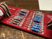
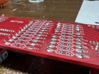
I just did a bunch of resistors on an attenuator board, and I wanted to ask if anyone had any comments or critiques on my soldering technique. I feel like I'm getting better at being more consistent, although the top aside shows variability in how much solder comes through the board.

Attachments

  • IMG_0049.jpeg
    IMG_0049.jpeg
    552.4 KB · Views: 214
  • IMG_0050.jpeg
    IMG_0050.jpeg
    452.5 KB · Views: 211

Infrasound production

good evening gentlemen I hope not to have the wrong section. I want to talk to you about a problem that has been bothering me for some time and concerns the production of infrasounds. So I know they are difficult to reproduce but I need them to have a more real effect in the movies. I did a lot of research and the secret lies in moving as much air as possible I could then use subwoofers inside a labyrinth reflex to increase the displaced air. Or a super pipe like those of the organ, or a bass shaker that reaches 5 hz, or even a rotary woofer but this is very difficult to create. I have listed all these methods for you precisely because I am confused. please tell me how to reproduce them. We are at Christmas, give me a nice gift

Fore Sale FR173B6-16L

I picked up a pair of these about 4 years ago and never got around to using them. Shipping in
the USA will probably cost me about $50 so I will take $80 including shiping for the pair or $35
if picked up in Tyrone Ga. Oh stock photo of this odd driver.

Attachments

  • 1989636-744cb86f-lot-of-4-airborne-17cm65-midbassmidrange-6-ohm-speakers-model-fr173b616l.jpg
    1989636-744cb86f-lot-of-4-airborne-17cm65-midbassmidrange-6-ohm-speakers-model-fr173b616l.jpg
    121.1 KB · Views: 96

Crate V18 with no PSU, got an idea

sup!, past weekend bought a Crate V18 guitar amp for dirt cheap, $30 (20.000 pesos chilenos), originally the owner brought me this amp to fix it, after some inspection noticed it hadnt a power supply at all, seems like someone removed it. The obvious solution is getting a new transformer, but its impossible for us, so instead of dumping it i asked him to buy it and he accepted instantly.


This amp has so much potential, also i've never had a 'serious' amp, what i could do? I thought about making a modding some transformer, but must be the cheapest possible. First I tried modding a MOT i had lying around and rewind it to get 350v, 6v and+- 12v however , just tried it today and god...that thing rattles just too much, also i read somewhere the construction of this kind of transformers is really not suitable for audio.


but what about modding an isolation transformer? they are not expensive at all, and the small ones seem good for this purpose(100 w or less)? The laminations are ok, power rating, everything sound fine to me, the only job is rewinding the secondary, what do you think about it?

Opposing loading of multiple driver Tapped Horns

Opposing loading of multiple driver tapped horns.. Why?


Having studied a lot of Danley Sound Lab’s tapped horns, I notice where he uses multiple drivers in one horn, he often reverses (loads the driver(s) with the cone facing outwards or inwards) half the number of the drivers with respect to the other half. IE in the TH812, there are four drivers inside each mouth, but I can see two of these drivers are loaded with the cone facing outwards, unlike the single driver subs, where the driver is loaded in reverse.

I’m wondering why this is. Presumably something to do with phase.

As far as I’m aware, this is not currently possible in Hornresp. So I’m wondering what the exact effect is.

Any ideas?

Simple SE tube rectifier troubleshooting

Hello all,

I am in the process of building a Tubelab Simple SE. I have the amplifier wired up, and both channels plays music nicely 🙂

One problem, however: The amp only functions in solid state rectifying mode.

When I switch to tube recitifying, I measure some strange voltages on the T1-YEL pins: 163 volts AC, and there are no B+. This happens with or without the tube rectifier inserted...?!

This is a little beyond my capabilities, since I am a total noob as far as tube amp building goes. Can anybody come up with any suggestions to the cause of this, and/or things I can try out?

Any help will be greatly appreciated 🙂

Morten

[noob] simulating a three-ways in vituixcad, some help needed :)

I have been pondering building some three ways speaker, using PA drivers which have been mentionned numerous times on this forum (15pr400,10pr320 and hf108).
I have a minidsp shd with Dirac, but I only have four channels, so I will have to add a passive crossover somewhere.

I used SPL trace from Faital and here is what I can do with all-active :
3waydigital.jpg


yet, the SHD only has two channels, so I thought I could plug one channel on the woofer amp and the other one on the mid-high amp. Here is what I did with vituixcad:

2waydigital-1waypassive.jpg


This doesn't look so good 🙁 I suspected replacing digital XO with electrical ones would mess it, especially when factoring driver impedance in.


Is this the right approach for a three way when only two DSP channels are available? What looked easy enough with a digital crossover is getting a lot harduous when adding some passive elements in the signal chain.

Thank you for your advice 🙂


-

Another UK Noob

I just noticed the intro thread.

I really am starting from scratch. Imagine a 5 year old looking over your shoulder 🙂
Loving the idea of making my own gear and learning some stuff.
Wanting to improve my SQ.
Realising that I need to start saving.

I am enjoying reading what you guys are up to. I am in awe.
If only I understood some of the words.

I just need to work out where to start ........

orion 2000.2 problem

i have a orion xtr 2000.2 .2 mosfets keep getting hot and blowing out ..the all getting the same voltage of 4 volts on the gate and the resistors good also 47 ohms it carries ...all other mosfets cold and the amp playing if i remove the 2 mosfets that over heating..

Attachments

  • IMG_20220201_133143.jpg
    IMG_20220201_133143.jpg
    523.4 KB · Views: 115
  • IMG_20220201_133156.jpg
    IMG_20220201_133156.jpg
    436.6 KB · Views: 120

Leaving SSE Driver Stage Unpopulated?

Bumped into this thread today:

https://www.diyaudio.com/community/threads/sse-as-single-stage-power-amp.222253/

I also have an aikido line stage I built using 12sn7s and have been thinking about an SSE build for a while.

I'm presuming it would be OK to just leave the driver stage unpopulated if I wanted to wire the inputs direct to the grid stopper? Between the driver tube and coupling caps, that's a nice bit of cost savings. Is this a safe presumption?

Hello from Finland!

Hello from Finland!

You can call me Tommi, DoomMetalDude or DMDude! 😀

I’ve been lurking here for years from time to time. But about few months ago i decided that i must start using my brains again. It’s getting really consuming to just sit here in my home. For two years now…

Little history, my experience in audio. It’s a short list, btw. 😀

In 90’s i built stereo covox (some of you might remember those fancy little thingies) for my 386 pc, as i didn’t have the money to buy a soundcard. It contained two octal D-flipflops and R-2R networks as stereo 8-bit DAC. Sound quality for a raging teenager was “satisfactory”. Way better than the internal speaker anyway. Little later i built simple preamplifier, i think it was based on TDA1524 or something. Vol, balance, bass and treble. It worked great, it’s still somewhere in my junkboxes. By great i mean it stayed alive, without breaking, despite my misuse. Sound quality, hmm, well… 😀 Then i built TDA2003(?) based amplifier, but burned it by accident. Then came the digital era, schools and work and it all got me away from audio, as AVR mcu’s and girls became “the thing”.

Oh, almost forgot. My first audio circuit was 8-bit AD/DA- converter for the mighty C64. It could store and play about 3.5sec of audio at maximum resolution. Nice times. 😀

I’m really bad at math, but i do have lots of experience in general electronics. It’s been my hobby in a way or another since i was teenager. For about 17 years i repaired, installed and serviced electronics in/for trams (among other things for them). Cronos dataloggers, scopes, low voltage, little higher voltages (600-1000V), you name it. Mainly repairing or measuring something.

I can make basic simulations in LTSpice, but the word “basic” may be rather vague in this site. I’m still learning it, as i’m nowhere near for simulating THD, noise nor PSRR. It’s left to be seen where i stand with my skills…

I’m a DIY-guy by heart and soul. Last thing i built (at work) was ITX-case for my little PC. I built it ‘cos i couldn’t find suitable, ready made case for it. Workmates helped with panel cutting, but everything else is made (and painted 😀 ) by me. Dimensions about W 170mm, H 252mm and D 320mm. Only thing still missing is DVD-drive. Maybe some day…. I'm also making a new wersion of it, it'll be in 3D-printable. But that'll take time, only a few pieces are drawn ready.

That’s it, short story of me. 🙂

I have a few designs, that i need help with. But all in time, may take a few days to put it all together in understandable form.

Regards,

Tommi, the DoomMetalDude.

Attachments

  • 20190926-IMG_6114.jpg
    20190926-IMG_6114.jpg
    295.5 KB · Views: 105
  • 20190926-IMG_6108.jpg
    20190926-IMG_6108.jpg
    370.2 KB · Views: 102
  • 20190926-IMG_6091.jpg
    20190926-IMG_6091.jpg
    309.1 KB · Views: 93
  • Edestä_2 (1).png
    Edestä_2 (1).png
    52.4 KB · Views: 102

Crown PS-400 repair question

Hi,

My sons ran my Crown PS-400 on the beach (Regatta) when a sudden downpour occurred. The amp was playing hard driving two large Klipsh near clipping. Needless to say, two outputs shorted and lit one Klipsh loudspeaker on fire!

The original MJ15150 outputs are NLA so I installed two Motorola MJ15022's as replacements which had comparatively low hfe (20) vs (100) for all the other outputs. While I was in there, I found all the small electrolytic caps to be bad (way under value ie: 22uf would measure 2uf). I replaced all the caps. The relay and 10 amp fuse also failed. Upon power-up, the DC offsets were a little off and so was the bias. after I reset the offsets and bias I decided to give my new to me HP8903A analyizer a go. I put a 8 ohm dummy load on it and here is what I got measuring distortion. The amp sounds good, and I set the DC offsets to 5mv as in the service manual, although, I could change them to zero. The bias is set to 430mv as in the manual also. My question is, what would cause the repaired channel to have more distortion and should I be concerned?

CH-1 original un-blown CH-2 Repaired

400hz @ 56v p/p = .016% .026%
1Khz @ 56v p/p = .018% .028%
10Khz @56v P/P =.075% .100%

Gary

Guitar intonation tuner app?

One way of adjusting the intonation of a guitar is to tune a given open string to the correct pitch, then press the 12th fret, pluck, and see if the pitch is exactly double. If it is a bit sharp or flat then the wedge or similar at the bridge end of the string is adjusted back or forth a little, then tune the open string to correct pitch again, then 12th fret and check for double pitch again... A lot of fiddling around retuning the open string every time.

What I would like to see is set the open string to nominally correct pitch then use that pitch as a reference to check for double because every time you adjust the bridge you also affect the open string. It would be good if you could pluck open, then pluck 12th, and if it is off then adjust the bridge and pluck open straight away again without having to first reset it. We are only looking for an exact 1:2 pitch ratio - not necessarily exact pitch at this stage. When it is finally adjusted right, if open string is right then 12th fret will also be right.

Is there an app that will do this - listen for a reference pitch, as well as have the normal absolute pitches built in? Maybe it's an idea for a new app?

Snell XA eXpanded array

Hi guys.
I find this solution very interesting and it seems to work really well. I would like to know more about it. From the measurements on Stereophile, the speakers using it seems to have really really well behaved off axis response, especially XA 90 PS. I think the designer is on here, speaker dave? I tried mailing him on here but was unable to do so unfortunately.
I am thinking i want to build something similiar myself. Something more akin to the XA90 than the XA reference because of size.

What drivers were used in the XA 90 and the Reference?
What distance between drivers?
Does drivers used in this type array need to hold any specific characteristics?
The crossovers seems to be LR2 electrical and LR4 acoustic. Anything more interesting in the crossovers?

Thanks. Hopefully the creator of these marvelous things chime in, if he is on here 🙂
Projects by fanatics, for fanatics
Get answers and advice for everyone wanting to learn the art of audio.
Join the Community
507,760
Members
7,887,261
Messages

Filter

Forum Statistics

Threads
406,173
Messages
7,887,261
Members
507,760
Latest member
The Fink