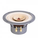
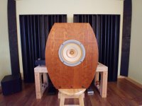
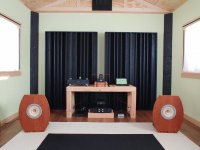
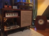
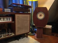
Pair of Acoustic Elegance IB15HT on Ebay

I am selling a pair of used AE IB15HT on Ebay they have been used a few years but are in good shape.
https://www.ebay.com/usr/bushinski
I tried to sell them installed in my dipole "enclosure" but don't think I'll have luck since it's bulky. So I might be interested in selling the enclosure separate.
https://www.diyaudio.com/community/threads/corner-dipole-subwoofer-for-sale-in-minnesota.383004/

Sansui BA-F1 pop/crackling

I have a friend with a BA-F1. I replaced the black flag caps for him awhile ago, proactively. He had been using the amp for about 6 months with no issue, but it started to make pop/crackle sounds on him, so he took it out of operation. I’ve asked him some preliminary questions (one channel or both, does music still come through despite the pop/crackle, etc). I’d love to help him fix the unit and get back running again if possible.

I recall reading that pop/crackle could be a symptom of a bad/failing transistor.

Are there known transistors that age badly/fail in this unit, or does anyone have any other leads/ideas on what could be causing this? I don’t have the unit with me and probably wouldn’t go get it until I had some leads on where to look first. If I got it here, I could probe here and there with the unit running to see if I could locate the bad component, but I’m also a bit worried that running it in that state while attempting to troubleshoot/locate the culprit could cause further damage. Last thing I want to do is blow output transistors or something else.

Appreciate any thoughts/leads.

Thanks.

The best midrange driver (cost no option) for 3-way

Looking for best midrange driver for 3-way diy project
it must be detailed and transparent
now i own Troelы Gravesen Cyclop
and around other speakers that i listend it has the best midrange

but 🙂 it was my 10th diy project so i plan my own 3.5way

the idea for new project
2 x h1411 seas in two different TL
the midrange in spherical cab or like midrange cab in B&W diamond.
and the twitter is HIQUPHON OWII in cab like B&W diamond too.

but i cant decide which midrange to use
the m15ch002 like in mine current setup or something else
maybe the ATC sm75-150?
or even accuton C90-6-078

any suggestions are welcomed

Noise in old germanium transistors (Fuzz circuit)

I'm building a Tone Bender Mk2 type 3 transistor fuzz pedal with old germanium transistors. Currently I'm swapping the Q1 transistor between various transistors I have. Some produce white noise like a gale down a chimney, others mostly quiet. These are for transistors with similar gain and leakage ( around x25 , 0.02mA ).
I can appreciate as you add more gain, the noise goes up, but why the huge difference for similar gain? Is it to do with their freq response, so the gain my tester measures is not at the freq of the noise?

looking for help to clone Acoustic Research AR-3

If a built clone was successfully done A kit might be the best option for this little experienced speaker builder. Most of my experience leans toward the cabinet making side, rather than the electronic side.

Plans for an AR3 would be awesome, if they exist out there in someone's folder.

Pictures don't hurt much either. I'm down to see some beautiful sealed cabinet working examples.

3rd Harmonic Distortion on E-I Iron Core - Low Pass filter

Hello!

I'm designing a crossover for a 200W 3-way loudspeaker (crossover frequencies 300Hz / 4kHz).
For the woofer inductor, I need 3mH. Considering price, size and "challenge", I chose to go with an E-I laminated iron core got from a 12V/1A transformer (360mm2 core section area).

I know 4 main drawbacks of using iron core.
Here's the way I worked around them for my case:

1. Saturation - The coil and core combination got saturated above 15A - I just need 10A peak (200W/4Ohm).

2. Non linear permeability - I used a gap in such a way that total permeability got limited to 15 - I built a 200uH air coil that when inserted in the iron core went to 3mH. Current x time curve looked quite linear.

3. Hysteresis - I measured the THD with the inductor in the circuit - got maximum 0.3% which is ok to me.

4. Core losses - Using it for a 300Hz low pass crossover frequency, no big losses I think.

Question: when I initially evaluated the THD, I found a strong 3rd harmonic at any power level, around -35dB below the fundamental which yields ~1.7% distortion).
After pulling my hairs for some hours, I decided to remove the core bracket leaving only the laminated core pieces. After that, the misterious 3rd harmonic fade out giving me what I wanted (THD <0.3%).

Anyone knows why the bracket creates the 3rd harmonic component?
I observed that when the bracket is mounted, the inductance goes up a bit - when I removed the bracket I readjusted the inductance by using a smaller gap.
I also observed the same with another ferrite rod core inductor that I had, when I get this braket closed to it the 3rd harmonic pops up too!

Here are the results and pictures.

Saturation Test
Saturation Test Iron Core 360mm2.jpg


Frequency spectrum of core with the bracket
Iron Core Perm 15x 6.5A with bracket.jpg


Frequency spectrum of core without the bracket (all harmonics below ~50dB)
Iron Core Perm 15x 6.5A.jpg


The inductor and the bracket
Picture Iron Core and Bracket Pic.jpg


Thank you!!

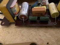
Tannoy Monitor Gold Crossover capacitor identification

Hi all,
Just starting a thread. I intend to optimize my sound system a bit. Step by step.
I finally opened one of my crossovers to look what's inside. I unsoldered one leg of the 16uf electrolytic cap and measured 18.6uf (+-5%).
I will give it a try and will replace that one with a good Polypropylene cap.
Not sure about the others. I basically want to leave them in there as I read many articles about the "right" replacement, there are many opinions around going from "leave them all original" to "bypass the treble selection switch" to "build your own or buy a custom crossover".
Anyway.
The yellow Arco ones: I guess these are film caps. Can anybody confirm?
But what is the the one in the brownish enclosure? I can't seem to find any information.

I can confirm the written values correspond with the values in the circuit diagram:
LF section: 16 uF
HF section: 1.5 uF, 3.3 uF and 6.8 uF

Basically I like the sound of my speakers, I have had them with me the last 25 years. I am currently driving the speakers with a Sansui 771.
I mostly have the loudness switch on and eventually have to reduce the bass. With loudness turned off the sound seem to be to damped.
My father once built the encloures, then had to cut them in half (because of my mother). Probably they are not the sweet point size now. 🙂
But hey: I like them.
He also put a lot of damping material inside, a friend told me to get rid of 60% of it, I have not tried that yet since then I probably I have to fix it somehow on the interior walls...

Do you think it is worth unsoldering the HF section caps an measure them?

Anyway basically I was just wondering about that brown cap.
The replacement for the 16uf is on it's way, I will report back when I have replaced them.

Cheers
Boris

Attachments

  • IMG_4882.JPEG
    IMG_4882.JPEG
    577.6 KB · Views: 281
  • IMG_4880.JPEG
    IMG_4880.JPEG
    630 KB · Views: 310
  • MonitorGold12_15xO1.gif
    MonitorGold12_15xO1.gif
    23.4 KB · Views: 347
  • IMG_4874.jpeg
    IMG_4874.jpeg
    771.5 KB · Views: 254

Suggestions for new build

I’ve been out of audio for a while and getting back into it finally. Looking for suggestions on next circuit to build. My previous project was a pair of mono blocks with power supplies on seperate chassis. 6cg7’s in John broskies aikido line amp configuration going into ltp with ccs and el34 push pull, topology on output tubes was basic 1ohm resistor to ground, and ul connections. Been trying to draw up the entire schematic on ltspice but having external difficulties. I do have a pair of output transformers from a jolida 302b el34 pp ul. What’s y’all recommendations?

Layout/connection picture

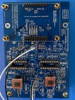
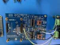
Please look closely at this picture for any errors. I’m going to solder most components from the bottom of the board, leaving only the jumpers and sockets on top.
R 13 will also be soldered on the bottom. I will also short SJ3. I’m looking for some small 3 pin connectors for the power supply wiring, might just solder them. I also considered using sockets for the jlsounds pcb. Is that worth doing? Once that board is soldered to those headers, that would be impossible to remove. Again, please take a look and advise
Thanks
This is just a mock up, anything can still be changed.
Second picture ground wires were added.

Attachments

  • CD12D98A-838B-475C-891D-CAE89722C322.jpeg
    CD12D98A-838B-475C-891D-CAE89722C322.jpeg
    453.8 KB · Views: 137
  • B7E060D2-5CBB-4332-AACD-F19104C732C4.jpeg
    B7E060D2-5CBB-4332-AACD-F19104C732C4.jpeg
    357.4 KB · Views: 125

CD Transport with SF-P101N (inspired by Shigaclone)

Hello everybody,

I was looking for a good CD transport for my audio chain and looking online I found this old but interesting project (https://www.diyaudio.com/forums/dig...affordable-cd-transport-shigaclone-story.html).
I would like to understand, is it still relevant?

If I'm not mistaken, the project in question uses the SF-P101N 16P mechanics available online for a few dollars.
My question is how can I drive it and maybe add a display?
Are there any PCB driver boards compatible with the 16 pin interface of the SF-P101N?

Thanks in advance.

Community Pro 3294 + S215 subs

Hi all, I am interested in the Community Pro S-3294 + S-215S subs, I intend to do outdoor parties of up to 200 people with it, Dj and live bands sometimes. I have not listened to the system but the person selling it said "This system is as loud as an equivalent JBL PRX/SRX system with a more pleasant sound quality"

Looking at the specs , it looks under powered with a max SPL of 123 dB continuous for the S3294 and 120dB for the S-215S. Can this system really be comparable to an equivalent JBL SRX?

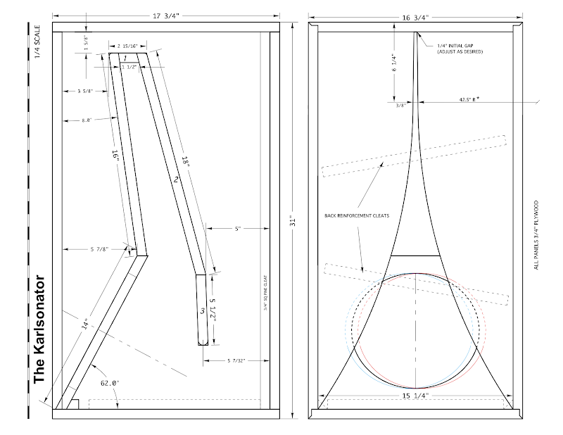
Karlsonator 12 for 12LTA

so far I've only run the Karlsonator 12 with the old Nirvana stamped frame Super10 - which was very "fast" sounding - the Karlsonator 12 works very well with Beta 12LTA augmented by a so-so Goldwood 1005 knockoff and I'll eventually load some of my coaxial including cast frame Eminence in several flavors, Beta10cx, Beyma 12cx and a P-Audio 12cx.

many thanks to Greg B. for the concept and plans and many thanks to TheJessMan for his superb realization.

my early impressions are very good for this Karlson variant - I recommend it.

The Build
https://www.facebook.com/media/set/?set=a.696242867088868.1073741850.601735219872967&type=1

dimensions - a larger plan is available at Greg B.'s album
Karlsonator.png


impedance plots obtained with a 50 ft run of 10 ga zip cord - just to show tuning

pyPVpGu.gif

Bs98N5b.gif


sorry for mess - gotta clean - I've a lot of chest pains. Note Earl's book holding
the wire for the piezo - lol

oekiaab.jpg


don't worry - there are plenty of screws for the wings- I popped the 12lta in the cabinet
for a short run but am pleased enough to let it be permanent.

An externally hosted image should be here but it was not working when we last tested it.

An externally hosted image should be here but it was not working when we last tested it.

For Sale Like New - Lii Audio , Fast 8 Speakers

For Sale - LIKE NEW , Fast 8 Speaker drivers ,

- Look like new, very nice , barley used - Beautiful Sounding - Full Range Drivers!

- Get your feet wet, see what all the talk and excitement is about! Check out Open Baffle Lii Audio Speakers!

- $ 150.00 - ( price for one pair of drivers only ) - plus shipping - only charged actual cost to ship.


-- see Open Baffle Ideas below --

Attachments

  • Fast-8-2-1.jpg
    Fast-8-2-1.jpg
    115.4 KB · Views: 214
  • Lii_Fast-8_a.jpg
    Lii_Fast-8_a.jpg
    72.3 KB · Views: 191
  • Lii_Fast-8_aA.jpg
    Lii_Fast-8_aA.jpg
    68 KB · Views: 166
  • Limages.jpg
    Limages.jpg
    7.5 KB · Views: 179
  • LLLC29.jpeg
    LLLC29.jpeg
    157.9 KB · Views: 184

ACA kit troubleshooting help

Anyone have a recommendation on how to fix low output level and severely distorted waveform on one side of my amp? The right side looks great, but the left looks terrible and is quiet. Not sure how to isolate the problem?

Sounds ok believe it or not, but quiet.

New Guy, so be gentle. Thank you all!

A 1V, 1kH, sine wave was put in.

Here's left side (bad):


IMG_1314.jpeg


Here's the right side (Notice the voltage peak differences):


IMG_1315.jpeg

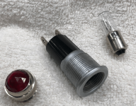
T2-1/2 bayonet socket defective from new?

Hi all,
Inherited an old but near pristine bench power supply. It has a total of five pilot lamps for the various outputs. The lamps don't work, even with fresh bulbs. Actually the bulbs in the unit test fine and light up when removed and voltage applied. So.. the T2-1/2 sockets must be to blame (yes, voltage does reach the sockets). After much head scratching (i mean can there be a simpler circuit?!) i discovered there is no connectivity between the top of the spring-loaded pin (to which the bottom of the bulb pushes) and its other end at the outside of the socket! Only two possibilities: (1) The sockets became defective after use, or (2) there was no connectivity from Day 1.

I'm inclined to disbelieve the former since there is no evidence of a short or anything else that might cause a failure (the sockets look like new) and the original (?) bulbs still light. It seems these sockets may never have worked. I'll order some new sockets. In the meantime i just wondered if anyone else has encountered such a thing?Screen Shot 2022-02-22 at 6.17.35 PM.pngScreen Shot 2022-02-22 at 6.17.51 PM.png

Transformer buzzing and heating up

I'm using a Triad VPT230-110 as the B+ supply for an Aikido all-in-one line stage. I'm running the transformer in series, red to orange jumped together, and the power supply in full-wave bridge configuration. I am regulating my AC input to 115V with a variac.

When I connect the transformer to the board, it buzzes, and rapidly heats up. Within a minute it becomes too hot to hold comfortably, and I dare not run it longer. With the leads disconnected, I measure 260VAC between the two leads, which is higher than the expected 230VAC. The transformer does not buzz or heat when disconnected from the board. When connected, the B+ voltage rises quickly to ~340VDC, then begins to decrease. I haven't been able to observe a stabilization point, because I am afraid to run the transformer that long.

The 12v heater power supply and transformer function as expected. All tests were done with both transformers connected and tubes installed. I have carefully examined the B+ power supply circuit for errors are defective parts, but have found no problems. I have ordered replacements so that I can rebuild the supply if necessary.

I observe a ground voltage potential of ~70VAC when the ground is floated. Swapping the input leads reduced this to ~25VAC, but did not improve the behavior.

I'm at a loss as how to proceed.

Attachments

  • Scan-2.jpeg
    Scan-2.jpeg
    227.1 KB · Views: 161

Operating a tweeter below recommended range

I’m fixing up some recently acquired GNP Valkerie speakers.
The tweeter and upper midranges were replaced with some Chinese made peerless 4ohm drivers.
I did as much research as possible, found that an upgraded version of the upper mid was still sold by scan speak .
Great!
From all I read, it sounds like the original 1” tweeter was a scanspeak.
However, all the 1” scan speak tweeters of the day ( late 70’s/early 80’s) had a recommended operating range of 3k-20k. GNP says the tweeter is crossed at 2500hz. The capacitor to the tweeter is 10mf which would give a crossover of 2650, not 2500hz.
I have two SEAS h174 tweeters that sound good in them and when I ran the audessey program through them , from 2500hz up, it’s pretty flat up to 20khz.
Is there anything wrong with operating slightly below operating range ( blow a tweeter??

Negative output impedance?? What am I doing wrong?

I tried to measure the Zout of my EL84 SE amp with the calculator on this page: http://www.sengpielaudio.com/calculator-InputOutputImpedance.htm
I had it connected to a 8.7 Ohm dummyload (output 15.9V), and then put a 10.6 Ohm resistor in series with the dummy. Output 19.84V (all peak to peak)
The outcome was negative?! -2.11 Ohm.
I've used this calculator for preamps, but this is my first power amp, I'm probably missing a lot but I don't know what.
Thanks in advance!

Monacor SPH-220HQ 8'' woofer in a 2 way

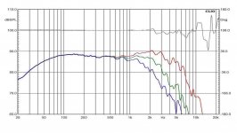
Hello, has anyone ever had experience with Monacor SPH-220HQ 8'' woofer? Here specs and measurements.
The declared response:
SPH-220HQ.PNG

and the measured one:
monacor_sph-220hq_risp.jpg

It seems to me a good woofer, with extension in both low and high regions and i'm wondering to use it in a 2 way system.
What do you think about?
What may be a suitable tweeter to use with?
Thank you very much!

Q about open baffle and cancellation front to back and bounce from the back wall

Just checking if I'm thinking of this right.

If the size of an open baffle leads to cancellation of the front and back waves say 24db down or whatever, buried, at 100hz for example, is the amount of that frequency that hits the wall behind it down 24db too?

Is it gone more or less at the baffle, or is there some other effect? Thank you!

Audio Reviewers, Are They Serious?

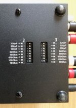
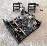
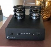
How can an audio reviewer mention this? :


" One thing you won’t be able to do with the Tube Box S2 MM/MC is swap out the tubes (not without some difficulty, at least)."

Best Phono Preamps of 2021 | The Master Switch

( see review 5 )

Have you ever used an Allen key? Once you remove the protection from the tube, you can do all the tests you want with other tubes, and when you are satisfied with one, close it!
I think the reviewer did not spend enough time to review, something more significant could have found .....
Have you removed the lid to see inside? Surely not ...

Attachments

  • Tube-Box-S2-2.jpg
    Tube-Box-S2-2.jpg
    78.4 KB · Views: 1,142
  • Tube-Box-S2-1.jpg
    Tube-Box-S2-1.jpg
    145.6 KB · Views: 1,094
  • Tube-Box-S2-Review-Big.jpg
    Tube-Box-S2-Review-Big.jpg
    48.2 KB · Views: 1,185

Oscillation found in Luxman LX33

Hi all,
I have an old Luxman LX33 which have considerably noise at the output (around 20mVAC, measured by my Agilent 34401A).

Traced around and I found oscillations at the Preamp outputs (actually the Baxandal-type tone stack): same frequency, amplitude and characteristics for both channels. The oscillations are at approx. 37kHz with amplitude rise and fall pretty fast (several times/second) from 0 to about 4mVpp (bass & treble controls at 50%; volume at min.).

So far I have tried and observed the following, but the result is still fruitless:
- swap/replace the 12AX7
- disconnect the amp's PSU, power the tonestack with separated HT & heater supplies
- oscillations seem to appear somewhere the output triodes
- amplitudes of the oscillations is at minimum (approx. zero) when Treble knob at min. and Bass knob at either min. or max; max amplitude is achieved at max. Treble and 50% Bass

Now I'm stuck here, please help me solving this.
Attached is the schematic of the entire amp and the tonestack (B+ for the tonestack is approx. 300VDC).
Thanks,
Duong

Attachments

Horn loaded 3 way

I’ve been modeling drivers and talking to various people for awhile now, designing a very high sensitivity 3 way for parties and the occasional DJ gig.
I’ll be using an SEOS waveguide for my CD (probably Beyma CD10ND) and a waveguide from limmerhorn for the 8NSM64, that’s specifically designed for that driver.
limmerhorn produces a waveguide for a 15” woofer as well. The woofer Im leaning towards is the Faital Pro 15FH520-4. It’ll be in a ported cab around 4cuft tuned around 45+ hz. They will NOT be full range, I will have dedicated subs 100% of the time. My question is, would I get any benefit from loading the 15 in that horn as far as directivity and SPL go? I’ve never heard of anyone doing this, but in theory it seems that horn loading this driver as well would make the directivity match much better, and I think if it works out audibly, that it will look incredible aesthetically as well. Thanks guys!
Also feel free to comment on any other of my choices and give suggestions if you’d like.

DIY valve radio

I have developed an interest in building my very own valve radio from scratch. I've built a lot of valve equipment, but I've never built a radio.

My wishlist for the project would be:

1) no SS components
2) FM capability
3) resistance tuned, no adjustable caps
4) octals look cool so go with them if possible!

I've looked thru a couple dozen radio schematics, and they all seem to have adjustable caps in them. Does anyone have any resistance tuned schematics to sugguest? Any other information for building a valve radio is of course highly appreciated.

Headphone protection system MOSFET

Hi People!

I'm thinking about building a headamp for IEMs. I want to protect them from being fried by DC in case something breaks. I think that MOSFET based solutions have advantage, so I'm here to see what do you think.

First questions is as follows. Is it better to use MOSFET with floating driver rather than drive them from eg opamp out? Using dual DC precision opamps would be super easy. Photovoltaic drivers are expensive and harder to get. Currents in headphone circuit will be real small, so I guess no need to go for a strong driver? I'm looking at PVI1050N in dual mode.

What kind of MOSFET should we use? I guess RDS(on) together with VGS are important here. IRF7301 is a dual, logic level (driven by 5V to max conductance), so it looks perfect. (it's kinda big though (SO8). Add opamp and filter and it is a quite a big circuit.

IEM headphones depend on very low noise and they work on very low voltages so anything else we should look at?

Response drop from 5kHz-> by room acoustics?

Hi,

the response curve of my system baffles me. Can the sudden drop 5k-10k be caused by room acoustics? Too much insulation? The room is quite small 8x4x3,1m. Huge dip in 45 is an obvious room mode, we actually moved the subs and basstraps after this and almost got rid of it.

The system: 18Sound 18NTLW5000 br sub, 2-way tops br 12NTLW3500, NSD1095N + XT1095. I've never used a CD and horn before, but these should go up to 15kHz easily (?).

Any ideas?

Thanks,
-V

2022-02-18 181334.png

Newby needs help 12v/5v lith/ion feedback noise

I built a wildlife caller from a car stereo mini amp and 200 w 6x9 speaker.i also added a Bluetooth range extender.i purchased a
Talentcell 12v/5v lith ion battery pack (model 1203000usb) to power both the amp and range extender but I'm getting all kinds of feedback.i emailed the manufacturers (amazon) but they won't do anything for me.is there a way to remedy noise? Thanks

We lost a good one...Larry Stafford S5 Electronics

I was just informed from Kathy that Larry Stafford passed three weeks ago of heart failure. He was the founder and owner of S5 Electronics and sold neat tube amplifier kits,(K-12G and many others) , hearing aid devices and antique truck parts....Talk about diversification! Kathy told me the company will be liquidated and cease operations. Not sure where that leaves the future availability of these fantastic "raspberry Pi" of Audio tube amplifiers.
  • Like
Reactions: Adriel

Understanding Hammond's Design Guide For Rectifier Use

I was wondering if I might ask for assistance regarding Hammond's ‘Design Guide For Rectifier Use’, and helping me to choose a power transformer for an amplifier. I have watched Uncle Doug's guides to rectification recently and thought I had it sussed, then started looking for a transformer and re-entered the land of confusion.

Here's the Hammond guide:

https://www.hammfg.com/electronics/transformers/rectifier

If I were to take one transformer as an example and work through with it 369BX: https://www.hammfg.com/part/369BX

The A.C. High Voltage Secondary (RMS) is given as 300V C.T. for this transformer. My first assumption here is that this means 300-0-300.

Working through the examples of HALF WAVE Resistive Load, FULL WAVE Resistive Load and FULL WAVE Bridge Resistive Load, here’s how I interpreted the guide:

HALF WAVE Resistive Load

V D.C. = 0.45 X Sec. V A.C. (All voltages RMS)

So I would interpret this as

V D.C. = 0.45 x 300V (from one of half of the secondary windings when centre tapped)

Giving 135V DC RMS with a lot of ripple

FULL WAVE Resistive Load

V D.C. = 0.45 X Sec. V A.C. (All voltages RMS)

So I would interpret this as

V D.C. = 0.45 x (300V + 300V) (from both halves of the secondary windings when centre tapped)

Giving 270V DC RMS and a lot less ripple

FULL WAVE Bridge Resistive Load

V D.C. = 0.9 X Sec. V A.C. (All voltages RMS)

So I would interpret this as

V D.C. = 0.95 x 600V (skipping the centre tap and having both halves of the secondary windings)

Giving 570V DC RMS

Is this anywhere near correct? I'm not sure I found Hammond's guide and docs all that straightforward, but that's mainly because it's all new to me and I'm not 100% sure I'm on the right path.

English language.

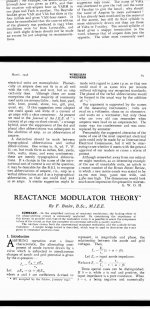
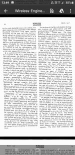
Hello all folks here. Days ago seaching in americanradiohistory.com for info for my FM tube tuner, particularly in what reactance tube is referred, in one magazine I found the following intetesting article. What's your opinons or comments several years later.

Attachments

  • Screenshot_20220122-134933.jpg
    Screenshot_20220122-134933.jpg
    306.2 KB · Views: 184
  • Screenshot_20220122-134924.jpg
    Screenshot_20220122-134924.jpg
    351.4 KB · Views: 188
  • Screenshot_20220122-134904.jpg
    Screenshot_20220122-134904.jpg
    242.9 KB · Views: 185

Starved filaments sound good: Why?

I have been dinking around with filament voltage (dc) on both my 841 driver and 801a output tubes. Yes, I am aware of the starved filament adverse impact to tube life. But, and this is really BIG, without a doubt (subjectively), the sound is much much better with a lower filament voltage. Yes, I have read Steve Bench's finding regarding lower distortion as a result of starved filaments. But, could that really explain improved bass, deeper bass, deeper soundstage, more transparency? Transparency and soundstage improvements are logical. But, much better bass? So, then I started to wonder about the Rp relationship with filament voltage. Bench and other state that Rp actually increases with starved filament voltage. So, the higher Rp (caused by the starved filament voltage) is counter intuitive to my experience. Other benefits of starved filaments is a more constant mu and gm.

So, any thoughts on why the sound is so much better. BTW: Initially, the driver was starved and improvements were clearly noticeable. Then, I said, why not also starve the output tube. This again gave further improvement, most noticeably in the bass / lower registers.

Schematic is below. Yes, I know I have a mismatch between the 841 Rp (20k) and the 68H IT. And for the record, I have confirmed that the 841 loves (requires) higher plate voltage. I am running at 535V. Bela suggests even higher at 600V.

Finally, I have inserted Rod Coleman's latest V9 filament regs. FANTASTIC. Eliminate all noise with the prior regs and also improved the transparency & soundstage. I need to work on bass sound pressure, but that is likely a function of the IT / driver Rp mismatch.

So, thoughts on the filament starvation?

Attachments

  • 841 IT 801A filament bias.png
    841 IT 801A filament bias.png
    385 KB · Views: 390

ITL MA-100 power amp - Help me find information!

Good morning ladies and gentlemen.

I hereby present you my trouble finding information on the amplifier branded with "ITL MA-100", an amplifier made in the UK. This particular unit has a calibration sticker from '89. Since I am in the job of repairing this poor bastard, I would like to find some more information on whether it is worth me hunting down the original parts (for the hardcore vintage collectors) or if I can take equivalent mosfets.

Can someone help me find some information on this device? It seems like I can at most find sale sites and auctions, and one or two repair threads.

If there hasn't been a lot of info on it, I guess that'll be my task then.

Cheers! Anna

Links to found info:
ITL MA-80 ein Kanal ist weg !, Hifi-Klassiker - HIFI-FORUM -> A thread about a repair on the complimentary preamp | contains inside pictures.

ITL MA 200 power amp - 2 Channel - HiFi WigWam ->
They were built in Portsmouth in 1988, the firm was brought out by B&W about 1990.

Cambridge Audio Azur 651c modification

I recently acquired an Azur CD player and, like many other owners of this well-built machine, was impressed with sound stage and detail but found the overall performance to be a little on the mechanical side. I feel this player is within a sneeze of being a stunning performer and am looking at mods that might do the job, possibly by replacing the NE5532 opamps that appear to be on the output. There are three of these for each channel and its not clear to me that all are doing output duty, or how they are configured to do so.

I have recently had great success replacing the NE5532s on a cheap Chinese Dac https://www.ebay.com/itm/333542970314?hash=item4da8b5d3ca:g:l6sAAOSwC2hgn6q5
with LM4562 opamps and doubling the capacitance on the surrounding electrolytics to 100uf. This significantly improved refinement and sorted out the bass but was still on the fatiguing side. Inspired by a capacitor shootout on the Lampizator site that showed tantalums providing a superior upper end, I bypassed the new Nichicon audio grade caps with 35v 10uF tantalums (the largest value I could get my hands on quickly).

Conscious that tantalums can be spiteful if abused I waited for the bang, but was rewarded with rich and full music that greatly exceeded expectations and showed potential to match vinyl, at least in my system. Repeating the experiment on a Rotel 820B produced an equally satisfying result after opamps and surrounding electrolytics had been given the same treatment.

As noted, the Azur 651c has three NE5532s that appear to be performing some function in the output of each channel with a 470uF capacitor nearby. The opamps are surface mount and it would require some kind of adapter to enable new opamps to be trialled. This looks like a solution: https://www.ebay.com/itm/312812470169?hash=item48d5137f99:g:f3YAAOSw8ENdHJIp

While I could just plunge in and see what happens, I would welcome any thoughts on proceeding.

Oscillation with D3a tube.

Could be Oscillation with D3a tube and not oscillation with 6e6p tube in the same tube amp.!

The amp is D3a 45 300B tubes.
I think the amp with D3a triode mode ( u =77) sometimes oscillate.

With 6e6p tube with less amplification factor ( u =35 ) i think NEVER oscillate.

Too much amplification voltage could be the cause of the oscillation?

Thanks a lot.

santitrucco

Resolved - Implemented Watched threads should default to showing only unread rather than all watched threads

Got it! A weekly email to let me know which of my watched threads have been updated would go down a treat. Thanks JP.
Should add to the list that watched threads here seems to now be defaulting to all rather than unread, which makes it decidedly less useful.

Power Adaptors / Units for audio uses

Hi. Hope this thread is kosher. Unless I do build a power supply in the end, I may want to purchase a power adapter or unit for a tuner board I have (from a Pioneer F-X77ZL). I'm guessing that board will not take more than 10W. I can identify some power adapters for sale, but I don't think I've yet come across one, or a type, that would be suitable for this tuner board. The adapter or unit needs to have pretty good ripple specs. I'm not sure whether I strictly need a linear unit or not. Are there suitable power adapters or units out there for sale that would be suitable for my tuner board? Thank you. I'm in UK. Rich EDIT: I'm in process of trying to buy a service manual for the F-X77ZL so I can glean wattage and supply voltage.

For those with 3D printers

Flame suit is officially on since this is firmly in snake oil territory. I was looking at those super expensive Furutech cable lifters and shaking my head when I thought why not just 3D print a small riser to hold up my sagging power cable going to my amp. I have my amp on Iso Pucks right now and the power cable was at a pretty big angle so I figured it wouldn't hurt. Measured and printed and I was 10mm over, so I redesigned and got it to fit perfectly. Placed the riser under the power cable right at the amp input and it was perfectly straight and I sat down to listen thinking I'd need to really analyze if I could hear any difference.

Well, what the heck!? Soundstage expanded considerably, bass extension skyrocketed and highs got very bright. I didn't believe it, so I went back and took it out and listened again and honestly I like the sound without it more because I am already used to it. I put it back in and the difference is pretty shocking and I'm going to leave it in for a few days to see what I think after some time. The only explanation I can think of is that the connection was loose originally (it was, the cable was just hanging out at a big angle even though it was fully plugged in) and by adding a support more of the blades were touching the male contacts on the amp. There is no vibration damping involved, just regular PETG filament but I couldn't believe how much just straightening the blades and providing more contact area would impact the sound. Treble is a bit bright for me now, a tiny bit shouty but I figured I'd post this cheap mod for people who have a 3D printer and have amps like mine that don't have an OEM death grip on the power cable. Strangely, my Topping D90 is such a snug fit that I have to strain just to get the cable pushed in all the way so it probably wouldn't do a single thing to that one. Worth a shot, was not a believer and it was a fun experiment and sure beats dropping big $$$ for an 'official' riser.
  • Like
Reactions: StevenCrook

LF drivers for sale, JBL2226J, TD-15M, ALTEC 515B

Greetings all,

Over the years in the hobby, I had accumulated many parts/drivers. Now that I am building the "dream speaker" TM, LOL, with TAD1601A that I acquired, I need do start selling them.

Before I put them on e-bay or other web-sites, I thought to offer them to the members first. As I had never done such, I have been thinking that I would provide history/description, and based on interest/requests, I can take hi-resolution pictures, e.g., with ohmmeter attached to show the integrity/resistance of the voice coil. Please let me know if this is acceptable.

1. JBL2226J, i.e., the 16 Ohm version

I have acquired a pair from Erich H, DIY SOUND GROUP. As I understand, they came from a church installation. I intended to experiment with PPSL, but the project never materialized, so that they were sitting in the shipping boxes ever since.

I think that a fair price would be $500 for the pair shipped, but I am opened to offers.

2. Acoustic Elegance TD-15M, the 8 Ohm version

I had purchased the pair directly from Acoustic Elegance, AE Speakers by Acoustic Elegance. I had measured both of them for T/S parameter, which I perhaps may still find. I built an enclosure and one of the drivers was briefly mounted and measured. However, shortly afterwards I acquire ALTEC 515B, which I had re-magnetized by Great Plains Audio, Home - Great Plains Audio, and briefly used them in the cabinets.

Since the woofers are essentially new, I think that a fair price would be $850 for the pair shipped, but again, I am opened to offers.

3. ALTEC 515B

I am not quite sure whether I really want to sell these, but, I am still putting them here for a consideration.

The drivers were acquired by an exchange from the late Dr. Bruce Edgar, and as noted above, sent to be re-magnetized by Great Plains Audio, Home - Great Plains Audio. I used them in the above-mentioned cabinet for a while. Unfortunately, the drivers have not performed in the cabinets, so they were removed and stored.

If there were serious interest, I would have to ask for $3000 for the pair, and I will not negotiate. Unlike the previous drivers, which are still available/produced, the 515B's supply is limited, furthermore, given the AlNiCo magnet, even the currently GPA produced have been steadily increasing in price.

Please let me know if you have any questions.

Kindest regards,

M
Trying to reduce distortion on an old Heathkit IG-72 signal generator

I've been working on a Heathkit IG-72 vacuum tube signal generator for fun, and as a learning experience. So far I have had much success. I've cleaned up all the switch contacts, installed NOS replacement tubes, replaced the electrolytic capacitors and all the 5% resistors (besides those in the attenuator). The wave output is now clean and stable across the full frequency range. However, I am not able to achieve the specified distortion figure of "Less than 0.1% from 20-20,000 Hz".

Through experimentation, I have found that the oscillator control is very sensitive, and only produces a clean signal in a small fraction of it's 600 Ohm range, less than 100 Ohm. Minimum distortion, about ~0.75 THD, is only achieved at the very lowest portion of the range, about 10 Ohms. Any lower and the signal drops out entirely. Any higher and distortion begins to rise. At this low end of the range, output voltage is reduced to about 1/10th of the expected ~3V.

This leads me to believe something is wrong with the circuit. I wouldn't expect the oscillator control pot to only provide clean output in such a small range, at the very least. At this point, I'm not sure where to turn.

I am getting what I take to be transformer whine at higher voltages. It varies in frequency/pitch as I adjust the controls. I think it's coming from the smaller of the two transformers.

Here is the manual: https://www.manualslib.com/manual/1854974/Daystrom-Heathkit-Ig-72.html

I did my distortion measurements using Room EQ Wizard through a Focusrite Scarlet.

Extra transformer wires

A lot of transformers have a bunch of extra leads. Which is fine. You can cut them off if you want, but if you decide to use the transformer for something else down the road, you're pretty hosed. Typically, you'd cut the leads short, but accessible, and tuck them away somewhere. Is there any reason you couldn't remove the end bells, and (assuming there's space) tuck them up in there (also assuming they're well insulated)?

Speaker surround foam or rubber can't find?

I have some Speakerlab 9 speakers I got cheap at the Goodwill, they actually sound great but the speakers need new surrounds and the problem is finding the right size.

I've tried ordering two times now from amazon but they are just a hair too big to fit the inside cone.

The outside diameter tip to tip is 6" but the inside diameter (measuring from old speaker) is 100mm or 3.93", this is the part that sits inside the cone.

I can't find anything meeting these diameters for the inside cone.

Any links to who might have these, within a price reason, would be appreciated. I currently have some spare 8 Ohm speakers in their place, which sound good but the originals were 6 Ohm.

Need advice: building Troels Mini Bookshelf, will add Woofer stand. Will this work?

Hello,
  • I had an old pair of Seas W15CY001, so deciding to follow Troels' mini : http://www.troelsgravesen.dk/SEAS_5INCH.htm
  • Later I would like to add 8" woofer separately for each chanel as speakers stand, woofer will be side mounted.
  • I possibly use Seas H1192-08 CD22RN4X
  • Woofer will use passive crossover. Connected to main speakers with external jumper. So these will work with single stereo amp.
speakerdesign.jpg


  • Will the woofer works with this cabinet volume, and with this mounting?
  • Since the crossover for woofer is passive, is there anything that allow me to adjust and change the level (woofer), like volume control?
  • Any example of crossover, build guide would be appreciated.

Sorry if any part does not make sense, I have not much experience building speakers.
Any advise would be appreciated.
Cheers,

irs2092s-based 2000W Amplifier? ("iraud2000")

While searching for a rather high wattage, high efficiency amplifier for a new project, I just found this:

Top iraud2000 d amplifier finished board high power 2000w irs2092s digital amplifier board on Aliexpress.com

What do you think of it? Is that bridged-mode rating "2000W @ 4 ohms" realistic? Would the transistors need some replacing in order to achieve that rating long-term?
Any better high-efficiency alternatives that can output 70...90V into 4ohms without being super-expensive? The system is high-voltage battery-powered. I want to avoid any large switching power transformation if possible.

Kind regards and thanks so much for your thoughts and ideas,

meko

Rockford Fosgate Punch 40.2

This amp appeared to be OK. It powers up and produces +22.60vdc and -22.63vdc. I input audio and it produces, but there seems to be some static or distortion. I disconnected audio and started checking.
What is an acceptable deviation from the norm on the +/- 15 volt supply?
Q8 is outputting 14.21 and Q9 is outputting -12.99.
Q8 "adj" voltage is 12.96
Q9 "adj" voltage is -11.73
Could this be part of the problem or what else to I need to check?

Bose PS321 II powered subwoofer - acoustimass connector pinout

Hi,
I got this sub woofer without any other accessories. It has acoustimass square connector as attached. Its a square connector with 13 pins. One is 27V DC and one has 2.4V. Rest of them reads 0 V. I am trying to find the pinout diagram for this. Internal circuit has DSP so it is not that straight forward to find connections. Can some one help me finding pinout ? My final target to use this subwoofer as another subwoofer in my sound system. I still hope that this unit has analog input. If it is digital, then I am screwed.

Thanks,
Pubudu

Attachments

  • acoustimass.jpg
    acoustimass.jpg
    8.4 KB · Views: 847

"natural" material for room acoustic treatment

Hi all,

So we all have used Rockwool or glass fibre for treating rooms etc... but now that more ecological, healthy materials are available, what do you think of them?
For example :
- Recycled newspaper panels with density of 32-42 kg/m3 available here in Finland (Ekovilla)
- Recycled cotton with density as low as 20 kg/m3
- Hemp
- Wood
- Sheep

What do you guys think when it comes to treating room and especially bass trapping

In Finland Ekovilla slabs (32-42 kg/m3) hasn't been measured but their blown wool of similar density has AFR of about 10 kPa*s/m2.

Manu
  • Like
Reactions: jamesblonde

Help understanding bandpass XO weirdness

Just trying to learn about this and I find there are at least four ways to do it.

Looking from source to driver:

1.series cap, series coil, parallel cap, parallel coil

2. series cap, parallel coil, series coil, parallel coil

3. series coil, parallel cap series cap, parallel coil

4. series cap, series coil, parallel cap, series coil

They all appear to use about the same values for caps and coils.

I assume they all would work, but is there any real electrical or audible difference?

ZEN-like headphones amp

I've built a scaled-down version of the Zen amp to feed my Grado headphones.
The HexFets employed are the usual IRF610, both for the active side and for the current source.
The bias current I chose is 300mA, the power supply voltage about 30Vdc, for the maximum compatibility with Hi-Z headphones.
I've obtained best results taking advantage of Nelson's patent 5,710,522, this allows to halve the distortion figure and to increase the drive caapability: on 32 Ohms load I've measured over 8Vp-p without any apparent compression, as soon as possble I'll perform a standard measuring set.
The sound is beautiful, more natural (notwithstanding Grados..) than the RA-1, which is not that champion people believe, at least in my opinion...
😉
The input impedance can be set between 13KOhm ( freq. respnse as far as 80KHz) and 40KOhm ( upper -3dB limit 26KHz).
If someone would desire the schematic, I'll send it to him gladly.

Finished project (3-Way Horn)

Hello, these days I have finished my first project with high sensitivity drivers and I wanted to show it to you.
I am very grateful to this forum since through it I have learned enormously, thank you.
The drivers chosen for the project are the following:
-Faital HF108 on B-52 PHRN-1014 Horn
-Faital 10PR320
-B&C 15 PS100
The midwoofer is housed in a closed box of about 14 liters. For the woofer I chose a bass reflex box with an approximate volume of 100 liters.
It is an active multi-amplification system commanded by the minidsp 4x10HD.
I am currently measuring the speakers with REW and adjusting crossover filters and EQ.

Regards.

_DSC5343-1 by Ivan Pelaez, en Flickr
_DSC5335-1 by Ivan Pelaez, en Flickr

[url=https://flic.kr/p/2jCoQgV]
_DSC5338-1 by Ivan Pelaez, en Flickr
_DSC5351-1 by Ivan Pelaez, en Flickr
IMG_20200625_131638 by Ivan Pelaez, en Flickr
IMG_20200705_101158 by Ivan Pelaez, en Flickr
IMG_20200705_101333 by Ivan Pelaez, en Flickr
IMG_20200705_101517 by Ivan Pelaez, en Flickr
IMG_20200710_172850 by Ivan Pelaez, en Flickr
IMG_20200716_194107 by Ivan Pelaez, en Flickr
IMG_20200807_155736 by Ivan Pelaez, en Flickr
IMG_20200825_161242 by Ivan Pelaez, en Flickr

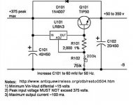
HV Tube bench power supply

Hello all
I’m hoping to get some help on a project I’m looking at doing. I want to build a bench power supply for my LAB that will provide a variable DC supply at about 100mA from a 240v ac supply from my bench isolation transformer.

The reason for this supply is to test valve amp projects before building the final circuit. I wanted the supply to be variable from about 10v to the full 300v dc.

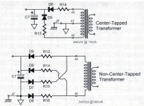
I have already constructed one design attached in image 1 below which for voltage control from 0v to 300v worked very well. However I have found that the output voltage can swing high when switching on as it is unregulated. I tried the circuit powering a heater element at 45vdc and when switching it on the voltage spiked to 55vdc then back down again. This destroyed the valve filament.

I am looking at the other circuit in image 2 which is a regulated supply. Has anyone built this and is it stable. What sort of output current could I get from this circuit.

I have an idea to build the first unregulated circuit for the plate voltages as this can be fairly unregulated, and then the second circuit for the heater elements at a lower input voltage about 80v ac.

Any help would be much appreciated I am a newbie to this I have experience with HV circuitry but not with designing the circuit.

Attachments

  • image 1.jpg
    image 1.jpg
    27.7 KB · Views: 1,748
  • image 2.jpg
    image 2.jpg
    52.6 KB · Views: 1,608

Fine crackling noise with RPi3 (Volumio) an Amanero-Cronos-Buffalo

Hello everyone.

I run a Buffalo-IIIsePro38 and run it with a Amanero-Cronus input. It sounds superb when I play music through my laptop connected via USB. However, when I use my Raspberry Pi 3 running Volumio (3.198) to play music a faint crackling noise is constantly present.

I already tried different power adapters, usb cables and settings in Volumio, but the crackling stays the same. Does anyone know this issue and can help out?

Best,
Stefan

YARRA Preamplifier Custom Case at Modushop

Hi Folks,
Just wanted to let everyone know that we have managed to get a very good deal on a custom case for the Yarra preamplifier.

Here is a PDF CAD drawing:
https://www.diyaudio.com/forums/att...melbourne-db-buy-yarra-preamplifier_gx383-pdf

746162d1553887745-yarra-preamplifier-hpa-melbourne-db-buy-yarra3-jpg


JPS64 came up with a superb mechanical and electrical design for this beauty. For a limited time, Hifi2000 (Modushop Italy) will be providing these for 100 Euro plus shipping (circa 20 Euro to USA). Once they have at least 22 orders placed, they will begin production.

You can read more about the details in the main Yarra preamp thread, but here is the GB interest list as it stands:

xrk971 - 1 case - USA
JPS64 - 1 case - USA
gary s - 1 case - Australia
Vunce - 1 case - USA
windwardmt - 1 case - USA
TungstenAudio - 1 case - USA
Meanie - 1 case - Singapore
Roundtoit - 1 case - USA
mordikai - 1 case - USA
afoor - 1 case - USA
Big E - 1 case - Canada
TboneAK - 1 case - USA
Sampsonite - 1 case - USA
jwjarch - 1 case - USA
batty - 1 case - Australia
MD_Stryker - 1 case - USA
jhofland - 1 case - USA
BEYoung -2 cases - USA (if possible)
ZUM911 - 1 case - Australia
Kokanee - 1 case - Canada
bk856er - 1 case - USA
BRN - 1 case - USA
urien - 1 case - USA

TOTAL = 24 cases

If you are interested, you can place your order online directly woith Modushop and they take care of all the logistics of payment and shipping. We just did the design and marketing for them. A big thanks to JPS64 for arranging this sweet deal with Hifi2000.

YARRA PreAmplifier Chassis
Projects by fanatics, for fanatics
Get answers and advice for everyone wanting to learn the art of audio.
Join the Community
507,753
Members
7,886,730
Messages

Filter

Forum Statistics

Threads
406,158
Messages
7,886,730
Members
507,753
Latest member
ayodej