I’ve been out of audio for a while and getting back into it finally. Looking for suggestions on next circuit to build. My previous project was a pair of mono blocks with power supplies on seperate chassis. 6cg7’s in John broskies aikido line amp configuration going into ltp with ccs and el34 push pull, topology on output tubes was basic 1ohm resistor to ground, and ul connections. Been trying to draw up the entire schematic on ltspice but having external difficulties. I do have a pair of output transformers from a jolida 302b el34 pp ul. What’s y’all recommendations?
I do have a pair of output transformers from a jolida 302b el34 pp ul.
You haven't measured the primary impedance by chance? I've always been curious what they actually are. Guessing maybe 4.5k - 5k.
jeff
KT77 versus EL34: similar tubes, but different sound. KT77 has better triode curves, which generally means better linearity.
https://www.diyaudio.com/community/threads/el34-single-ended.380006/#post-6865043https://frank.pocnet.net/sheets/163/k/KT77.pdfThe JJ KT77 were cheaper than the EL34 too, last time I ordered some.
Another recent upgrade scheme is to take some small positive feedbacks from the output tube cathode resistors, back to the driver stage grids or cathodes (phased for pos. current FDBK) to compensate for OT primary current (xRpri) voltage loss thru the primary resistance. This removes the magnetizing current effect (and hysteresis effect) along with eliminating effectively the OT primary resistance loss (better damping factor). This should yield OTL like sound -with- an OT. Or OTL sound -without- the heat. ( Positive current Fdbk level adjusted to -just- remove the OT primary resistance, using a negative resistance effect)
Don't know what you are using for the driver tubes, but several super linear tubes are available:
ECC99, EH 6SN7X/6H30 Octal, 5687, 12HL7 (super linear in triode)
Similarly for the front end, some super tubes available:
6S45P, 6F12P, 6J49P, Raytheon (Japan) 6JC6A (super linear in triode mode)
Or for simplicity, 6LQ8 or 6KV8 gives you both input and driver tubes in one bottle for each side of the P-P. ( 6LQ8 and 6KV8 pentodes are super linear in triode mode)
Of course, using LTP stages throughout the front end cancels the main 2nd H distortion of cheaper tubes, so super linear tubes are something of a gold plated overkill. But lower higher harmonics with the super tubes. Sparkling Bling or bragging rights at least.
Last edited:
I can second the 6JC6A tubes triode strapped. I used some in a KT88 SE amp and they sounded fantastic. 6EJ7 tubes are also nice triode strapped.Similarly for the front end, some super tubes available:
6S45P, 6F12P, 6J49P, Raytheon (Japan) 6JC6A (super linear in triode mode)
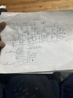
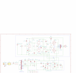
The existing schematic looks pretty good, assuming the 6CG7 sections are matched. 12AT7 is a high 2nd H distortion driver in SE mode, but fairly good in
diffl. mode over a CCS ( high 2nd H cancels, and the 12AT7 is normally low in higher harmonics ). I guess the OT is set up for 4.5K P-P for 40+ Watts.
The KT77 datasheet says it was specifically designed for ultralinear mode. Users say it has more of the big tube sound than EL34. (less compression due to the lower/sharper plate knee voltages) And while the KT77 UL curves do look like some of the best UL ones around:
https://www.audiomatica.com/tubes/kt77.htmThey still do not bring to my mind an "ultra-linear" picture. You might want to consider some "local" N FDBK at the output stage or back to the driver stage, instead of UL. Simplest way being to add a high R and isolating C from each output plate back to the corresponding 12AT7 cathode (with small value resistors between the 12AT7 cathodes to the CCS for signal insertion, see below too) (the isolating C's could be eliminated if the N Fdbk resistors are high enough value and the CCS is upped to compensate the driver cathodes DC level )
Having some low value resistors in the output tube cathodes already, they would make for an easy addition of Pos. current Fdbk back to the driver stage to cancel OT primary resistance and magnetizing/hysteresis effects. Just some high value resistors from the output cathodes back to the corresponding 12AT7 driver cathodes, with some added (maybe 1K) resistors between the 12AT7 cathodes and the CCS. Have to experiment with the FDBK resistor values to get the optimum OT resistance cancellation. The CCS will need a neg. supply and some adjusting to get the same driver tube currents. Too much pos. current FDBK and you get an oscillator, but the amount needed for OT resistance correction is much less.
I don't see any global N Fdbk in the schematic. Local driver N FDBKs can sub for that (and UL), especially with the OT primary resistance removed.
Last edited:
OOPs, more like 100 Ohm cathode resistors added to the 12AT7 cathodes for signal insertion. 1K ones would up the output Z of the 12AT7s too much.
And 10 Ohm resistors in the output tube cathodes (instead of 1 Ohm) for current sampling would allow higher value Pos. current Fdbk resistors (trying to keep the 12AT7 CCS useful).
And 10 Ohm resistors in the output tube cathodes (instead of 1 Ohm) for current sampling would allow higher value Pos. current Fdbk resistors (trying to keep the 12AT7 CCS useful).
Last edited:
I’ve been going over my previous amp build just making sure i did it all properly, and I have a question. Which el34 would be considered the positive phase to hook up the lundahl opt? How do you tell which leg if the ltp phase splitter needs to be considered the positive phase? Or does it matter?
I used the 1ohm resistors so I could hardwire 100mv analog meters to keep an eye on the bias. Is it better to have the 10ihm with no way to monitor bias?OOPs, more like 100 Ohm cathode resistors added to the 12AT7 cathodes for signal insertion. 1K ones would up the output Z of the 12AT7s too much.
And 10 Ohm resistors in the output tube cathodes (instead of 1 Ohm) for current sampling would allow higher value Pos. current Fdbk resistors (trying to keep the 12AT7 CCS useful).
The Fdbks in this case(s) just go from the output tube to the driver tube that is driving that tube's grid.
Your could leave the 1 Ohm resistor (from ground) for the bias setting meter in, and just series connect another R (8.2 or 9 Ohms,whatever) for the current sensing tap at the cathode. .
Your could leave the 1 Ohm resistor (from ground) for the bias setting meter in, and just series connect another R (8.2 or 9 Ohms,whatever) for the current sensing tap at the cathode. .
I should add that although the UL curves for these (EL34 & KT77) power pentodes look somewhat non-linear due to the closer spacing at high plate voltages, this section is progressively over-lapped in class AB operation, greatly equalizing the spacing along the load-line by summation in the class A portion. UL operation is not as bad as the UL tube curves look. So even if the local N Fdbk alternative does not suit one's taste, falling back to UL mode is still an acceptable outcome here. With KT77 purposely designed for UL, you would likely still see some improvement.
Another option for the local voltage N Fdbk approach is to take the N Fdbk signals from the UL taps, rather than directly from the plates. The UL taps are typically more closely coupled to the secondary, just for UL Fdbk purposes, for most UL optioned OTs. This will give lower distortion, but may put one closer to instability due to the Fdbk signal loop passing partly through the OT (in auto transformer mode). One just has to try this out for a given OT to see if it is working OK. The N Fdbk resistors get modified for each case to provide the same effective N Fdbk. ( ie, 40% lower value Fdbk resistors from 40% taps versus from plate taps, with some DC correction maybe needed.)
Another option for the local voltage N Fdbk approach is to take the N Fdbk signals from the UL taps, rather than directly from the plates. The UL taps are typically more closely coupled to the secondary, just for UL Fdbk purposes, for most UL optioned OTs. This will give lower distortion, but may put one closer to instability due to the Fdbk signal loop passing partly through the OT (in auto transformer mode). One just has to try this out for a given OT to see if it is working OK. The N Fdbk resistors get modified for each case to provide the same effective N Fdbk. ( ie, 40% lower value Fdbk resistors from 40% taps versus from plate taps, with some DC correction maybe needed.)
Last edited:
Oh, another issue develops when these Fdbks resistors are taken to the 12AT7 driver cathodes, the CCS gets loaded some and will not split the signal into equal amplitude phases as well. Hopefully one can just change one of the 12AT7 load resistors to equalize this again. Otherwise, it may need to have the front end incorporate a phase splitter ahead of the 12AT7s. Several approaches there, a gain stage and Concertina or a differential stage, or others.
The present gain structure will be OK if the local Fdbks only use up the same gain as the UL did before, and no global loop is to be added. Otherwise some additional gain up front will be needed. The present 6CG7 Aikido front end only contributes a gain of 10 (half of Mu). A higher Mu tube like 12AY7 (mu 44) could be used there (same pinout). Otherwise changing to a different front end/splitter can use a higher gain tube. 6F12P has been popular lately, with a mu 70 pentode and mu 100 triode in it. Can be set up for either type of front end, with the diffl. type splitter cutting the effective mu by 1/2. Lots of other tube options. 12AX7 still around as usual, mu 100. 6JC6A with mu 60 or 70 (brand), 6J49P with mu 44 or 50 (selection), 6J9P (mu 36), 6J51P/EF184/6EJ7 with mu 80, 6S45P with mu 52, .....
The present gain structure will be OK if the local Fdbks only use up the same gain as the UL did before, and no global loop is to be added. Otherwise some additional gain up front will be needed. The present 6CG7 Aikido front end only contributes a gain of 10 (half of Mu). A higher Mu tube like 12AY7 (mu 44) could be used there (same pinout). Otherwise changing to a different front end/splitter can use a higher gain tube. 6F12P has been popular lately, with a mu 70 pentode and mu 100 triode in it. Can be set up for either type of front end, with the diffl. type splitter cutting the effective mu by 1/2. Lots of other tube options. 12AX7 still around as usual, mu 100. 6JC6A with mu 60 or 70 (brand), 6J49P with mu 44 or 50 (selection), 6J9P (mu 36), 6J51P/EF184/6EJ7 with mu 80, 6S45P with mu 52, .....
Last edited:
Bill Perkins on Pearl-HiFi has an artcile "Pentodes and Tetrodes to Triodes". Basically using a zener of 33V (with some bypass cap) to drop the voltage to the screen. The article mentions a string of zeners but private correspondence mentioned that a single 1/2 watt zener will works just as well.
Spanneburg and Schade both mention that ideally the screen in a beam power tube should be 15 ~ 20 Volts below the plate.
I'm using that principle in UL and it changes the linearity due to the space charge in the tube. The zener value changes depending on the DC resistance of the output transformer, in my case I am using a 22V zener to give a 20V difference. (Tried 33, 30, 27, 15).
Found in SE UL / CFB it makes a (large? how long is a piece of string? <wink>) difference in distortion level.
YMMV.
I’ve been going over this and not sure if I’m following correctly. Gonna have to review it a couple more times and draw up what a schematic and make sure before I require.The existing schematic looks pretty good, assuming the 6CG7 sections are matched. 12AT7 is a high 2nd H distortion driver in SE mode, but fairly good in
diffl. mode over a CCS ( high 2nd H cancels, and the 12AT7 is normally low in higher harmonics ). I guess the OT is set up for 4.5K P-P for 40+ Watts.
The KT77 datasheet says it was specifically designed for ultralinear mode. Users say it has more of the big tube sound than EL34. (less compression due to the lower/sharper plate knee voltages) And while the KT77 UL curves do look like some of the best UL ones around:
https://www.audiomatica.com/tubes/kt77.htmThey still do not bring to my mind an "ultra-linear" picture. You might want to consider some "local" N FDBK at the output stage or back to the driver stage, instead of UL. Simplest way being to add a high R and isolating C from each output plate back to the corresponding 12AT7 cathode (with small value resistors between the 12AT7 cathodes to the CCS for signal insertion, see below too) (the isolating C's could be eliminated if the N Fdbk resistors are high enough value and the CCS is upped to compensate the driver cathodes DC level )
Having some low value resistors in the output tube cathodes already, they would make for an easy addition of Pos. current Fdbk back to the driver stage to cancel OT primary resistance and magnetizing/hysteresis effects. Just some high value resistors from the output cathodes back to the corresponding 12AT7 driver cathodes, with some added (maybe 1K) resistors between the 12AT7 cathodes and the CCS. Have to experiment with the FDBK resistor values to get the optimum OT resistance cancellation. The CCS will need a neg. supply and some adjusting to get the same driver tube currents. Too much pos. current FDBK and you get an oscillator, but the amount needed for OT resistance correction is much less.
I don't see any global N Fdbk in the schematic. Local driver N FDBKs can sub for that (and UL), especially with the OT primary resistance removed.
- Home
- Amplifiers
- Tubes / Valves
- Suggestions for new build