Taramp 3k bass burnt power trace.

Well I got this taramps 3k bass from a buddy said it was blown and I could have it. We'll checked none of the fets were shorted so I took out the board from the heat sink. Wow ...taramps need to move this brass bar they put on the trace closer to the terminal. I did because it burnt all the way through it. I wish I took a pic before I fixed it. But my question, do you think this fix will suffice or should I bridge the top of the board too?. And this 10ohm 20w resistor was cracked. After a closer look. It melted the caps ..although i think they wernt compromised. They look worse than they are. Do you think this is related to the power trace failure. The amp is working. Then I seen the resistor and seen all the heat that was generated.so i tore the caps and resistor out. I hope it was related. BTW this amp was probably hooked up with too small of wire and god knows what ohm load the speakers were wired at.. with the gain high. With no regard to what clipping is.. some people....thanks guys.
20250304_015555.jpg
20250304_015544.jpg
20250304_015438.jpg
20250304_015349.jpg
20250304_015338.jpg

12V pure sine wave Inverter using op-amps.

HI all.
I want to make a inverter powered by a 12V wall-wart adapter to power valve heaters with the low side then drive a center-tapped mains transformer in reverse to get the high plate voltage.
Online I see mainly square wave drive designs, but I think this is a bad idea for a high gain valve preamp, so I set up a simulation.
inv_1.png

I plan to use a XR2206 or ICL8038 for a basic sine wave generator.
I like the idea of using a sine inverter and can run the transformer at a higher frequency for easier filtering and adjust voltage by a potentiometer after the function generator IC.
This design outputs 130Vac. does this look like I'm on the right track?

3 way speakers

I'm in the final stages of building my first pair of 2 way speakers and already thinking what next. Ive built plenty of subwoofers. When I started this 2 way project it was originally going to be a 3 way but I must have heard at least a half a dozen people tell me not to go 3 way since it is a way more complex build. I reluctantly decided to go 2 way and Very glad I did. I learned a lot on this 2 way build but what I didnt learn is why are 3 way builds so much harder? Isnt it just an extra driver and crossover. Is it that much more difficult to match up 3 drivers? Anybody care to educate me on the subject? I'd appreciate anybody willing to take a few minutes to explain it to me. This forum has been a huge help for me already so thank you for that

paging lowmass

hey @lowmass the science says a slightly curved array would perform better but that would require mounting some ribbons in orientation less than vertical ...

considering the ribbon is "free swinging" once it stretched out a bit from normal use overtime would it then begin to sag for those ribbons that are angled slightly upwards ?

the array would start off from the ground plane as perfectly perpendicular to it ( vertical ) but gradually curve backwards so that the ribbons at the very top would be angled back maybe 20 degrees ...

i am guessing plastic ribbons would be fine, but the way arrays work is they lose HF at 3db/octave because of the weird array math which means i need the loudest ribbons possible and can't use plastic ones - they have to be pure aluminum like Aurum Cantus

HELP ! ! !

SARA-2016

A simple scheme and pretty

Attachments

  • SARA-2016 schematic.jpg
    SARA-2016 schematic.jpg
    370.7 KB · Views: 6,704
  • clipping 1khz.jpg
    clipping 1khz.jpg
    297.7 KB · Views: 6,152
  • clipping 20khz.jpg
    clipping 20khz.jpg
    293.6 KB · Views: 3,673
  • defajaz 1khz-20khz.jpg
    defajaz 1khz-20khz.jpg
    283.5 KB · Views: 3,392
  • IMD (20+19)khz - 1to1 - 50w - 8ohm.jpg
    IMD (20+19)khz - 1to1 - 50w - 8ohm.jpg
    299.9 KB · Views: 3,252
  • loop gain, phase margin, gain margin.jpg
    loop gain, phase margin, gain margin.jpg
    290.8 KB · Views: 1,016
  • slew-rate.jpg
    slew-rate.jpg
    293.8 KB · Views: 983
  • THD-1khz-8ohm-1w.jpg
    THD-1khz-8ohm-1w.jpg
    297.2 KB · Views: 1,087
  • THD-1khz-8ohm-50w.jpg
    THD-1khz-8ohm-50w.jpg
    298.5 KB · Views: 1,170
  • THD-1khz-8ohm-100w.jpg
    THD-1khz-8ohm-100w.jpg
    282.2 KB · Views: 2,391

Replacement transformer for NAD C352

Hi all,
I am trying to repair a NAD C352 amp. The symptoms are that it powers on to an orange standby LED, and when you try to power it up, the relay on the power board clicks but nothing else happened.

I originally thought it was due to dead caps on the power board (they're notorious for this) but I later also determined that there is a shorted diode on the power board in the rectifier circuit, and also that the transformer itself is completely dead. I have determined this by measuring continuity on the primary and there's nothing. Completely open. And when you power it up, no voltage whatsoever on the secondaries.

I am trying to see if I can find a suitable replacement transformer but I am struggling to work out what voltage I need.

Can anyone have a look through the service manual and help me out?

https://elektrotanya.com/nad_c352_sch.pdf/download.html

Many thanks!

TDA2050 amplifier board

Needed a small amp to replace the underperforming amp for a speaker and found this.

https://www.amazon.com/HiLetgo-TDA2050-Amplifier-Digital-5W-120W/dp/B0CDWTL57H

Aside for a couple altered resistor values, the amp is the circuit shown in the datasheet.

https://www.st.com/resource/en/datasheet/cd00000131.pdf


TDA2050 amp altered values.png


The amp works good for what it is.

The plan is to use the second one for testing purposes to see just what this amp is capable of.

I'll do two things.

1. Use a 4 and 8 ohm load powering the amp at 24Vac with an audio generator supplying the signal and oscope across the load to see what the frequency response is and how much power it puts out.

2. Find the lowest resistance for R4 that keeps gain above 25dB (1dB higher than datasheet recommendation for safety) and the highest resistance value including R4 that keeps the amp stable while keeping a flat frequency response. I'll then use a fixed resistor to set the lowest gain and a trimpot in series. That way I'll have a variable gain.

I may also pick up two more of these amps and run them bridged to see if it's possible to eliminate the speaker coupling capacitor. That would limit me to an 8 ohm load though which will be fine. The phase splitter for testing will be an Edcor transformer with a 15k center tapped primary and secondary, however if the amp is proven successful I may either use a dual OP-AMP as a phase splitter or use the amp with balanced sources. The phase splitter could be built in a separate box with various inputs or I could use a balanced preamp if I actually decide to do anything with these amps at which time I'd add speaker protection as well given no speaker coupling caps.

ROAR18 - Large build and response measurements

Long story short:
7x ROAR18
with different drivers tested, measured, used at a DJ gig in a 500-person venue with impressive results.

Pros: Lots of headroom, especially in the kick range, usable up to 120 Hz and possibly higher.
Cons: Needs EQ in the low end for a balanced sound, big and maybe a bit too heavy for one man to throw around.

The long story:
A friend of mine wanted "decent" sound everywhere in his big barn where he works on his hobby (cars) and asked me for help. It didn't have to be very loud, but it's a big place, about 20 m x 10 m x 11 m (LxBxH), so a single sub wasn't going to cut it. Knowing his taste in music a little, I knew he wasn't necessarily looking for the lowest possible notes, but a tight kick was definitely needed. Instead of designing something from scratch, I thought Martinsson's ROAR18 might do the trick. This was helped by the fact that I had already built and listened to the ROAR15 just to see how it would sound. Although it didn't get very loud in the low end, it responded pretty well to EQ at the expense of max SPL (40Hz was certainly doable).

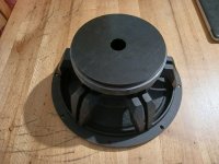
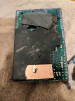
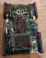
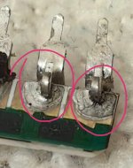
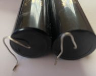
The ROAR18 seemed to dig a little deeper on paper, especially with a small "mod" that I did: use ALL the internal volume available (so the long channel is about 10 cm longer; this seemed to simulate fine: a bit less sensitivity in return for a little lower response). So I figured it would also do well with some rap music (also a prerequisite). And another big factor was that I had a couple of different 18's lying around, plus a bunch of broken and discarded 18's at work, where I was happy to pull them out of the trash (with permission)! They were Celestion CF1840JD's that needed their magnets realigned as the glue had failed, so it was quite an operation with a few recones involved.

They were not the best for the ROAR18 (not the biggest BL), but they simulated ok. So I decided to build a ROAR18 to evaluate. After listening to it, my friend approved and I set out to build 6 more, since that number matched the cut list of 15 sheets of plywood (244x122 cm) and the number of 18's I had on hand; hence the odd "7".
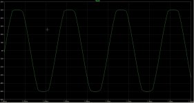
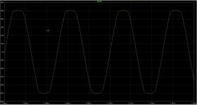
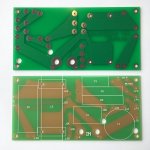
First one built:

IMG_20240617_211030.jpg


IMG_20240619_152037.jpg


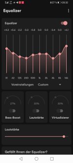
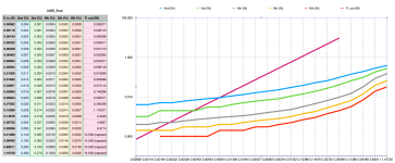
In-room measurements with and without EQ:
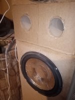
IMG_20240619_161412.jpg


The large build:

With wood prices through the roof, I opted for cheap underlays (32 Euro/sheet) because they were for a permanent installation and didn't need to be "road proof". The three that were for me (the white ones in the photos) I laminated with epoxy/fiberglass. These latter ones had wheels and weighed a whopping 84 kg.

IMG_20240728_154002.jpg

IMG_20240818_152808.jpg

IMG_20240908_160744.jpg

IMG_20241009_171855.jpg

IMG_20241019_173346.jpg


I finished them a few weeks ago and asked another friend of mine at a place called "Landbouwbelang" in Maastricht, the Netherlands, if I could measure them there since they have an outdoor space with little interference from nearby walls and such. He went one better and asked me if I would like to try them out at a party that was going to take place there in two weeks. Yes, of course!

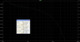
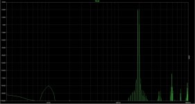
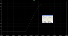
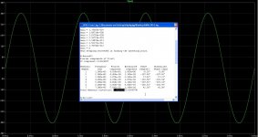
Measurements were taken at 2.83 V, no filters or EQ, with the mic at 1 m on the ground and the speaker facing the river, see photos. Everything seemed fine, although the 109 dB/W at 106 Hz seemed a bit high to me, but I double-checked my measurements and levels...
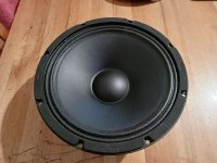
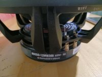
IMG_20241026_133250.jpg


The drivers are:
-5x Celestion CF1840JD (8 Ohm 1200 W RMS/2400 W program)
-1x Celestion CF18VJD (8 Ohm 1600 W RMS/3200 W program)
-1x Beyma 18P80Nd (8 Ohm 800 W RMS/1600 W program)

The measurements were done with Umik-1 and REW V5.20.13.

Measurements.png

I think the measurements and photos speak for themselves 😊.
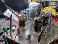


The gig:

IMG_20241102_170553-edit.jpg

(left and right of my setup are the in-house system speakers, Xtro + 186 Horn)

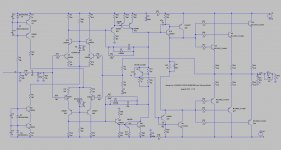
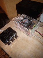
The setup for the gig was as follows:

1x Nova DC8000 processor
2x Powersoft D4002 bridged to 2x CF1840JD subs on left and right stereo channels, delayed to 45 cm -> 4000 W into 4 ohms (these are the black subs on both ends in the show setup)
1x Powersoft M50Q channels 1 and 2 bridged to the CF18VJD sub and channels 3 and 4 bridged to the 5th CF1840JD -> 2x 2500 W at 8 ohms (both mono summed)
1x Powersoft D2002 bridged to the Beyma 18P80Nd sub -> 1x 1200 W at 8 ohms (mono summed)
1x RAM Audio S6004 for my Synergy tops (build link here: https://www.diyaudio.com/community/threads/synergy-horn-for-135-db.305852/) -> 2x 1480 W into 4 ohms.

The HP for the Roars was set at 27 Hz and 48 dB/oct. I set the LP quite high at 120 Hz and 48 dB/oct because I wanted to hear how they would handle kick and sub duties.
I used a 6 dB low shelf at 50 Hz with 6 dB gain and a 3 dB bump at 40 Hz with a Q of 2.871 (or 0.5 octaves). To even out the room modes, I delayed the outer 4 subs by 1.31 ms (or 45 cm), which gave a nice even sound throughout the venue. The limiters were set conservatively on RMS, but allowed peaks to get through.

The headroom was kind of absurd (at least in my book), which is of course a good thing: all night long the -9dB lights on the amps were occasionally tickled, only during the VERY LAST song they turned it up to -6 dB peaks, which was still enjoyable, but not for much more than one or two songs.

There were many compliments on the quality and amount of bass, and apparently it was much more powerful than the in-house system consisting of two XTro tops and four 186 horn subs. I was also pleasantly surprised with my 2" Synergy horns, they easily kept up!

Here is a playlist with a few videos taken with my phone:
https://www.youtube.com/playlist?list=PLZ9IxQRaHpo8qlY31TOXkLRJ4tjH5XnTm

Now I have to figure out where to place the subs in this big barn I built them for in the first place...
But maybe there will be another gig before they are permanently installed😎.

Any questions, remarks, comments, suggestions, let me know 🙂

Eton Woofers construction problem!

Dear DIY People,

“Just” as info :

I noticed some construction problems in some Eton 7-375/32 HEX (in 2013-2014, I thought it’s a "casual" thing!) and then again I have the same problem in 2018-2020 with some Symphony II 7-312/C8/32 HEX!
The wires connection that goes from the terminals to the coil hits the cone during excursion.
We can mainly notice it when the woofer reproduce continuos low frequencies with excursions of +-2mm or more, and it's not just a question of "noise", it brings also to higher distortion.
Incredible to believe that we can have such a basic mistake on this price point drivers (over 200,00€ per piece),
NOT necessarily all drivers have this problem! Some does (more or less pronounced) some don't. Question of luck.
ALL DEPENDS on how "carefully" they glued the wire to the cone! Above the glue point the cable is very close to the cone.
I guess they should have found a better solution that it's not so sensitive to human error.

I will try to attach 1 photo and a Video (at the end of the page). In the videos is clearly possible to see-hear what I mean.
The test was made at 30, 35, 40 and 45 Hz, and I did the same test with drivers of the cost of 20,00/40,00€ values and there was no any noise! 🙁
But it’s enough to play records like the Billie Eilish one and you will clearly ear it…

P.S.
I wrote many email to Eton, just to share my experience and to "help" them for the future... NEVER any kind of answer.
I also wrote few times to Klang&Ton and to Mr. Holger Barske (email and Facebook) thought that they should be interested on this kind of concern... NEVER any kind of answer. 🙁

Eton 7-312-C8-32HEX-sm.jpg

View attachment Eton 7-312-C8-32HEX-Video-CutSm.mp4

Thank you for the attention!
Take care and great DIY building to all of you!
Andrea

Foster FE108e∑ sunk dustcaps

Hi guys,
My youngest son pressed his little finger on both fostex108ez used in my Cornu speakers, and they are all sunk.
How would you guys fix this? They are quite small and the vacuum cleaner sucking option, which I use regularly on my subwoofers does not seem to be an option here. Material looks fragile, and I don’t want to further mess things up.

Any advice would be strongly appreciated!!
Cheers,
Fran

Introduction

Hey everyone, my name is Joseph, and my current system is a pair of Klipsch Fortes, where I instantly fell in love with the horn sound. I am working towards making my own 4 way active crossover horn speakers to upgrade to. I am starting with learning all about the function and science behind horns and how they are designed. While I won't be able to design my own horns for a long time, I still like to learn about how and why things are designed and made the way that they are. I am also learning about ciruit design so that I can possibly design my own amplifiers in the future. It is a lot of fun for me to learn new things, and this forum has a great wealth of knowledge that I hope to be able to tap into in the future.
  • Like
Reactions: krivium

Acoustat TNT 120 hum issue

I have a TNT120 that I have owned since 1984 along with a AGI 511a pre amp and Magnepan MG1b's and just updated to LRS+'s.
I have always had a very low hum out the speakers from the beginning that couldn't be duplicate at store. It still happens with only the amp plugged into 110v socket with the ground connected or not and the speakers connected with Kimber wires. The manual states "The only Way to prevent this hum is to float this ground".
Any help would be nice. Thanks Larry

Attachments

  • 20250213_135014.jpg
    20250213_135014.jpg
    317.8 KB · Views: 31
  • 20250213_132049.jpg
    20250213_132049.jpg
    338.7 KB · Views: 26
  • 20250213_135035.jpg
    20250213_135035.jpg
    233.9 KB · Views: 28

Show your outdoor / fun loudspeakers

I think the time has come we have to show our fun loudspeakers or outdoor ones.

Here my contribution (outdoor fun speaker) :

Cheapo drivers with diy aluminium sandwich cones. (there is a thread on it here on diy audio forum).

DIY whizzer cone and extra bass with 1mh inductivity forming a one and a half way system (=fullrange with added bass).

Cheapo TDA7498 amp with 34 Volt smps power supply. And whuzi audio preamp Bluetooth
with certainly only fake parts. But works.


Simple EQ with smartphone app.

Drivers were only 10 dollars but decent quality if you know how to use it.

IMG_20240330_202406.jpg

Attachments

  • IMG_20240330_202534.jpg
    IMG_20240330_202534.jpg
    373.5 KB · Views: 117
  • IMG_20240330_202612.jpg
    IMG_20240330_202612.jpg
    291.7 KB · Views: 128
  • Screenshot_20240330_203212_com.jazibkhan.equalizer.jpg
    Screenshot_20240330_203212_com.jazibkhan.equalizer.jpg
    82.9 KB · Views: 126

I2S Audio Not Working on Orange Pi Zero 2W (Allwinner H618) with MAX98357A

Armbianmonitor:
https://paste.next.armbian.com/egohivineg
Hardware:
  • Board: Orange Pi Zero 2W (Allwinner H618)
  • Audio Module: MAX98357A (I2S)

Connections:
  • BCLK → PI13 (Pin 7)
  • LRC/WS → PI14 (Pin 16)
  • DIN → PI15 (Pin 31)
  • 5V/GND → Properly connected

Software:
  • Armbian Version: 25.5.0-trunk.147 (nightly)
  • Kernel: 6.6.75-current-sunxi64

Configuration:
/boot/armbianEnv.txt:
overlay_prefix=sun50i-h618 overlays=i2s param_i2s=on

Problem:
  • No sound output via MAX98357A.
  • aplay -l returns "no soundcards found".
  • dmesg | grep i2s shows no output, indicating the I2S driver is not loaded.
  • Missing I2S overlay: Checked /boot/dtb/allwinner/overlay/ — no sun50i-h618-i2s.dtbo (only I2C overlays are present).
  • Loaded sound modules: Only snd_soc_hdmi_codec (HDMI audio).

Steps Taken:
  1. Verified physical wiring (BCLK/LRC/DIN, 5V/GND).
  2. Updated to the latest nightly build (25.5.0-trunk.147).
  3. Added overlays=i2s, param_i2s=on to /boot/armbianEnv.txt.
  4. Tried manual driver load: modprobe sun8i-i2s (no effect).

Questions:
  1. Is I2S support for Allwinner H618 available in kernel 6.6.75?
  2. Are there plans to add sun50i-h618-i2s.dtbo in future releases?
  3. Is there a workaround to enable I2S on H618 (e.g., custom DTB)?
  4. Would upgrading to kernel 6.7+ resolve this?

Diagnostics:
uname -a:
Linux orangepizero2w 6.6.75-current-sunxi64 #1 SMP Sat Feb 1 17:37:57 UTC 2025 aarch64 GNU/Linux

cat /etc/armbian-release:
VERSION=25.5.0-trunk.147 BRANCH=current BOARD=orangepizero2w

dmesg | grep -i i2s: No output.

Request:
Any guidance or patches to enable I2S on H618 would be greatly appreciated. Thank you!

Applying GaN transistor as a replacement of SiC rectifier

Kazuo Ozawa and Bunpei are collaborating in a new application of GaN transistor as a replacement of SiC rectifiers for power supplies used in digital audio devices. They think this is a novel approach and worth sharing on this forum.

For these years, Kazuo has made his efforts mainly on improving Salas Reflektor type and Taylor Follower type regulators. Recently, he applied GaN transistor, GS66502B of GaN Systems as a replacement of SiC MOSFET, C3M0280090 of CREE and obtained a satisfactory result.
http://john.asablo.jp/blog/img/2016/12/19/458cae.png
http://john.asablo.jp/blog/img/2017/01/17/460d69.jpg

On the other hand, Bunpei has tried such SiC rectifiers as manufactured by CREE, Rohm, Infineon. His latest favor was Infineon G6. He read Kazuo's blog post and thought, "Is there any GaN rectifier? That must be interesting."
There was a hint on a technical presentation given by Sanghyeon Park and Juan Rivas-Davila.
https://superlab.stanford.edu/poster/APEC2017_slides_Sanghyeon.pdf
They said, "Tying the gate to the source makes GaN transistor behave like a diode.". Bunpei's first attempt was not successful because the GaN transistor got very hot in his environment. He asked Kazuo to apply GS66502B with his custom board especially designed for cooling.

At the beginning of this month, Kazuo reported his first result on his blog page in Japanese,
GaN Transistorをダイオードとして使う: Konちゃんの虫眼鏡
expressing his very good comments on the new rectifiers. He applied the GaN transistors in PSU of full-wave rectification for an OCXO master clock generator.

Bunpei immediately purchased GS61008T, which has a thermal pad on its top , and followed Kazuo's approach. Bunpei applied the rectifiers to PSU of full-wave rectification with both 4 diodes type and 2 diodes type. Those PSUs are used for Chiaki's SDTrans384 SD memory card transport, ES9038PRO Dual Mono DAC and NDK DuCULoN OCXO master clock generator.
Bunpei's impressions for the new GaN rectifiers were very similar to those given by Kazuo. Both of them felt something very new and remarkable in the improvement of resultant sound quality. "It's a kind of quantum leap!"

Kazuo and Bunpei hope that DIY audiophiles on this forum will confirm their claim is not any bluff and will have a happy music.

You can easily purchase those GaN transistors, products of GaN Systems via Mouser. For cooling, Kazuo designed a special circuit board and Bunpei soldered a small piece of copper plate on the thermal pad of the GaN chip.

MISCO Bold North Audio XBL2 midwoofers look interesting

Looking for a woofer to anchor a 3-way and I stumbled across these: 6501 and 6502. Voice Coil magazine also tested them. I would only use the 6.5" for a center channel, but they have an 8" coming, I was given a very tentative date of June '22. XBL2 motors are known for their very low harmonic distortion in the bass, and these are a good example. But after reading a lot of the Purifi info, I took a closer look at some of the Klippel results like BL flatness and especially symmetry, and Le(x) tilt. These appear to be solving some of the same issues that Purifi identified, like FFM distortion. Now I'm not comparing the two, the usage case different, and Purifi obviously went much further in nailing down the behavior of the driver. But it does seem these are performing very well in the ways that audibly matter vs most other manufacturers. Thoughts?

Digging through the closet

Now that I am retired I am hoping to finish projects and move them on before my family has to. I dug these out, built them 25-ish years ago. Mostly the Andrea Ciuffoli OTL v8.2 with a few changes to fit the transformers I had. Operating at 150v/200ma -52-ish v bias. 44W at clipping, the driver stage clips first. An ambitious project at the time, 5 total transformers. I am going to modify to a SRPP first stage based on the tubedvr design.


6c33-1.jpg

Attachments

  • 6c33-2.jpg
    6c33-2.jpg
    372.7 KB · Views: 56
  • Like
Reactions: Klimon and 6L6

Hello DIY Audio community

Hello, I'm currently on a speaker build journey for my final project of University, focusing on material and modularity to elevate home speaker design to be more inclusive and adaptable to its environment, allowing its users to change its aesthetic. This project was born from the ambition to limit product vulnerability from trends, aesthetic boredom, and home decor changes, encouraging users to have a longer-lasting connection, which lengthens the product lifespan and how much the user will engage with the product overtime.

I'm looking forward to conversing with you and developing my knowledge and understanding for the science of speaker design.

Help! Fixing a "James" Discrete Class D BTL Subwoofer Amplifier

I am repairing a "James" subwoofer model 6 amplifier "see schematc". I got it running, but it has 13% distortion and the output filters are hot, 100 degree C.

It is a bridged design and the (pos side) pwm is 1.8 khz IC13 pin 6 while the (neg side) pwm IC 4 pin 6 is 360hz. Shouldn't these signals be the same?

Thanks, Gary

Attachments

For Sale Zilchlab Econowave Crossover PCBs

FS: Zilchlab Econowave Crossover PCBs

attachment.php


Before Zilch passed away he asked me to keep these crossover boards available and in consistent production for speaker builders everywhere. Pairs are available direct from me for $32 shipped CONUS w/instructions. Send me a PM if you'd like to build a pair of Zilch's Econowave speakers.

For more specific build information check out the massive original thread here on Audiokarma: Zilch's AK Design Collaborative - Econowave Speaker | Audiokarma Home Audio Stereo Discussion Forums

Not to mention Flex Your PCD Mettle on the Parts Express site where he really picked up steam: Flex Your PCD Mettle: - Techtalk Speaker Building, Audio, Video Discussion Forum

Attachments

  • Econowave PCBs.jpg
    Econowave PCBs.jpg
    134.9 KB · Views: 7,380
  • Like
Reactions: wwschaff

Do you use AI?

forced Grok-3 Beta to digest my Edelweiss-3 amplifier using Tesla strategy, step by step refining calculations of details then back to the whole thing, pushed Grok-3 to use real anode V-I curves for a typical KT-88 and driver tubes, to account to non-linear internal resistances of tubes with complex nested feedback loops, and got final calculations that correspond to what I measured and heard. The graph is for the case of negative 3.8 Ohm output resistance, with positive output resistance they are almost the same, with insignificantly lover distortions. It confirmed that in my amp there is no sound difference between EL34, KT-77, 6CA7, 6L6GC, KT88 and even LS-50 tubes, the end result is still the same with minimal adjustments, thanks to the overall design with nested feedback loops.

Attachments

  • Screenshot 2025-02-25 at 8.05.17 PM.png
    Screenshot 2025-02-25 at 8.05.17 PM.png
    553.6 KB · Views: 66

FAQ power inductors

Q: What is the operational role of power inductors in Class-D amplifier circuits?

A: In Class-D audio amplification systems, power inductors perform critical filtering functions through these primary mechanisms:

LC Filter Core Function
Collaborating with capacitors to form:
  • 2nd-order low-pass filter topology (typically 50-500kHz cutoff)
  • 40-60dB attenuation of PWM carrier residue (300kHz-1MHz range)
  • 90%+ suppression of harmonic distortion components
System Performance Optimization
Key selection parameters for modern high-performance designs:
  • Miniaturization: 1210 to 2520 case sizes with <1.2mm profile
  • Efficiency Enhancement: <0.05Ω DCR at 3A load conditions
  • Thermal Stability: Maintain stability from -40°C to +125°C
  • Saturation Resilience: 20-30% headroom above peak current (I_sat ≥ 5A)
  • EMI Mitigation: <5nH parasitic capacitance configuration
AEC-Q200 compliant automotive-grade options
These magnetics enable Class-D amplifiers to achieve:
✓ >90% power conversion efficiency
✓ THD+N <0.005% @20hz-20kHz
✓ 85°C ambient temperature operation
✓ MIL-STD-202G compliant vibration resistance

Typical applications: automotive infotainment, professional PA systems, and compact IoT audio solutions.

Tannoys DC1000 + Lowther Acousta

I'm ready to test this marriage between a pair of my dc1000 driver's & some empty Lowther horn cabinets. The initial listening test was quite positive. Great fun. The Tannoy units TS parameters were close to figures I've seen for Lowther PM6's.
The little horns cut off too early for deep bass but the impression of depth is certainly an improvement on the lowthers. I know that's not what the Lowthers are all about but I enjoy experimenting. I might tinker with the crossover after testing but it doesn't sound bad to my 'mature' ear.
  • Thank You
  • Like
Reactions: GM and wchang

Difference between CS8673 and TPA3116

What is the difference between the D amp chips?

Is the CS8673 inferior to the TPA3116?

I cannot read Chinese Data sheet - who can say something on this chip?

@Karlsonate gave me a hint:

https://www.diyaudio.com/community/threads/unboxing-zk-mt21-tpa3116.403857/post-7467281

Some subjective comparison between mini amps:

https://www.diyaudio.com/community/threads/unboxing-zk-mt21-tpa3116.403857/post-7501910

For Sale 2x SB Audience ROSSO 12MW300 Midwoofer

SOLD
Used lightly and limitedly for various applications/experimentation.
Reboxed and ready to ship

Shipping:
€16 within Ireland
€30 to a few of the nearest european destinations (UK, Germany, France, Netherlands, Belgium), otherwise very expensive.

Attachments

  • eyJidWNrZXQiOiJtZWRpYS5hZHNpbWcuY29tIiwia2V5IjoiY2E4YmQyZGExMTYwMjkwNjBmZjliZTY5YTdlM2E4ZDMyMT...jpg
    eyJidWNrZXQiOiJtZWRpYS5hZHNpbWcuY29tIiwia2V5IjoiY2E4YmQyZGExMTYwMjkwNjBmZjliZTY5YTdlM2E4ZDMyMT...jpg
    70.6 KB · Views: 230
  • eyJidWNrZXQiOiJtZWRpYS5hZHNpbWcuY29tIiwia2V5IjoiZGFmYjc5YzlhY2E4NDA3OWQ0YzUxMzEyZGEzZjcyZTdlN...jpeg
    eyJidWNrZXQiOiJtZWRpYS5hZHNpbWcuY29tIiwia2V5IjoiZGFmYjc5YzlhY2E4NDA3OWQ0YzUxMzEyZGEzZjcyZTdlN...jpeg
    67.3 KB · Views: 238
  • eyJidWNrZXQiOiJtZWRpYS5hZHNpbWcuY29tIiwia2V5IjoiZjk2NTJkMGNlZjdkMzg5ZTAxYjdlZmQxODJhMjFlNjkxZ...jpeg
    eyJidWNrZXQiOiJtZWRpYS5hZHNpbWcuY29tIiwia2V5IjoiZjk2NTJkMGNlZjdkMzg5ZTAxYjdlZmQxODJhMjFlNjkxZ...jpeg
    48.1 KB · Views: 241

Bob Cordell's VinylTrak

Bob Cordell's Linear Audio Vol 4 article 'VinylTrak - A full-featured MM/MC phono preamp' led to a discussion that resulted in much additional material.
Bob has been so kind to place this on his website.

I'll shortly put up a link from linearaudio, but if you are interested in this stuff the additional material itself is well worth a read.

And, of course, if you want to reach out and actually touch the equipment (or Bob 😉) find us in the lobby at the RMAF coming weekend!

jan didden

DUAL CV40 phono input - load modification

Hello - I'm restoring a Dual CV40 amp to use with a Shure M95 G-LM cartridge (requires 47k input load).

I have a question regarding the modification of the resistive input load in the phono preamp (schematic attached).

If I understand correctly, in the set up shown, the signal sees the resistive load formed by the series resistor R2 and the parallel network of R1, R3+R8 (1.5k + approx 77k) - is this correct?

If I wanted to bring the load down to approx 47kohm, changing R1 to approx 53k should do the job?

Thanks in advance for your help!

Martin


DualCV40_phono_input.png

Completed Aleph J boards (diyAudio store boards) - $50 plus shipping

THESE BOARDS ARE SOLD. THANKS FOR LOOKING. These amplifier boards are the universal mount style from the diyAudio store. The jFets are original Toshiba 2SJ74/2SK170 that I had left over from earlier projects. They are matched. The IRFP240 Mosfets are quad matched with all 4 on a channel matched. Putting the funds toward an SET tube amp project.

The price is $50 plus shipping and I am shipping from Michigan US.

Attachments

  • Aleph J back.JPG
    Aleph J back.JPG
    294.5 KB · Views: 101
  • Aleph J close.JPG
    Aleph J close.JPG
    446.6 KB · Views: 100
  • Aleph J front.JPG
    Aleph J front.JPG
    389.3 KB · Views: 95
  • Like
Reactions: Gill.T

1949 electronic sackbut 6as6 subcircuit

Hi diyaudio!

it's been a while since I've posted but I was wondering if any of you might be able to chime in on my latest research project.

Last time I was writing here I was looking for help on a hi fi amp i was building for my undergrad senior thesis. A few moves and thirteen years later I'm now a researcher at the Canadian museum of science and technology working to reverse engineer Hugh Le Caine's electronic sackbut instrument, which is part of their collection.

https://en.wikipedia.org/wiki/Electronic_sackbut#

My circuit analysis friend and I are a little stumped by the suggestion of a colleague that the 6as6 tubes in the oscillator section of the device are frequency counters: no feedback, no RC circuit with a time constant to flip flop a square wave at a defined rate. Just resistors:

1740962493703.png

I'm including two of the four stages. the caps on the left of the 6as6 stages go to a transformer coupled blocking oscillator. The output exiting left of the plate goes to a mixer-so the stages don't cascade. I really think this is just a buffer / gain stage to couple the aforementioned blocking oscillator to the strange resistive mixer that follows these pentodes.

I realize this is more of an amp forum than a synth forum, but since these pentodes really do look like a coupling stage to me (rather than a counter stage) I think we are squarely in the amplifier section of the tube circuit topology realm.

In short though - is there any conceivable way a pentode, wired like this or something like this (the circuit tracer may have missed something!) could act as a clock divider (e.g. take a square wave and output other square waves at ratios of the original frequency)?

Thanks in advance for your perspective, and let me know if there's additional info you might like to answer this more accurately!

DC Heater buzz in series connected tube heaters

Hi all,

I am trying to modify the attached circuit to use two parallel section of a 6922 tube for the gain stage instead of the 6GK5 while keeping the second 6GK5 cathode follower. In a previous version of this mod I had the two parallel section of the 6922 followed by a mosfet buffer and all worked fine.

The heaters are 12.6 DC regulated DC heaters with the tube connected in parallel. The original circuit had the two heaters for the 6gk5 on each channels connected in series. With the first tube a 6922 I can no longer do this as the 6922 and 6gk5 heater have different impedances and thus the voltage on each heater will not be the same. I modified the heater supply to feed two 6922 in series and the two 6gk5 heaters in series. both of these are connected in parallel to the 12.6v regulated supply. In doing so I am getting a high buzz on the output of the preamp. Music is playing and it looks like the voltages measure OK but the buzzing is very high. Any idea what's going on?

Thanks,
Ron

cj p14.png

Magnavox CDB460: Return, repair, or harvest?

I'm the new owner of a Magnavox CDB460 (one of the models with a TDA1541 inside) that I picked up for $80 shipped. The seller said it "works great" but of course now that I've got it here, it won't read any discs. It wasn't packed super well, so something could have rattled loose in transit.

It powers on, the tray opens and closes, the disc spins, but then reports "ERR" on the readout. Interestingly, it does the same thing without a disc inserted -- motor spins for a couple seconds, then reports "ERR".

I popped off the cover to observe, and I don't see any light from the laser at any point in the process. I don't have a service manual, so I haven't broken out the multimeter just yet.

The seller is offering to refund 20% and let me keep it, or refund the whole amount if I send it back.

I'm a tinkerer -- I've cleaned and recapped a Marantz 2215b, I've put together a shortwave radio from a kit, and I've built some simple guitar pedals. I don't have any experience servicing CD players, but I'm happy to learn. Does this sound like it's worth repairing?

Another possibility is to harvest the relevant bits from this unit and put together a TDA1541-based standalone DAC for use with other digital sources. But I don't have any experience with that, either.

For Sale Resistor groupings and some silver wire

Here are a few groups of things hopefully someone can find use for. Each group / item is priced individually with USA shipping included. I will give a shipping discount for multiple items purchased.

1) Twelve 25 or 50 watt wire wound aluminum chassis mount power resistors. If you cannot read the values, let me know. Asking $20 shipped.

2) Twelve Tantalum resistors, older Audio Note and Shinko: 1/2 watt: two @ 390R, two @ 1K. 2 watt: two @ 47K, two @ 100K, four @ 300K, asking $20 shipped. SOLD

3) Large cement 8 ohm leaded dummy load, 6 1/2 x 1 1/2 inches. 100W free air, 200W sinked. Asking $10 shipped.

4) Sixty older Kiwame japanese carbon film resistors, good to at least 750 volts. 46 @ 2 watts, 14 @ 5 watts, if you need a list of values, let me know via PM. Asking $50 shipped. SOLD

5) 4 or 5 - nines silver wire remnants with 20 gauge insulation tubing included: 4 ft. of 24 ga mundorf gold/silver alloy, 7 ft. of 24 ga, 4 ft of 20 ga. Also a spool of over 50 feet of 30 ga teflon coated instrumentation wire that now goes for 8$ a foot....Asking $50 shipped. SOLD

payment via Zelle or Paypal.

USA Shipping only.

IMG_1772 2.jpegIMG_1782 2.jpegIMG_1803.jpegIMG_1781 2.jpegIMG_1736.jpeg

Suggestions on a Brickwall Limiter/Compressor

Hello,

I'm looking into possibly using a compressor/limiter between my souncraft signature12 mixer an my F5m amp. I want to primarily use it as a "Brickwall' limiter to ensure the amp never sees more than 3V.

I want to be able to set a threshold voltage, in my case 3V as opposed to setting a ratio like 10:1 or 20:1 since that is less accurate. I'm also looking a solution which has short attack and release times. I rather not design my own hardware for this, but would be willing to build a DIY.

I've looked at Rane, DBX, Empirical Labs Distressor, Waves C4 and a few others but they are packed full of features I don't need or want. I just want the Brickwall limiter and not color the signal.

Does anyone use such a device or have suggestions where I can find a simple device with not so many additional features? ( I plan on getting a 19" rack to mount my amps and other related gear )

Breathe new life into old Line 6 L3T Speaker?

Howdy!

I recently acquired this non-functioning PA cabinet that I've heard awesome reviews about but have no way of using. After a deep dive into plate amps and DSP, I've decided to see if I can use a Fusion FA253 (250w, 250w, 100w triamp) to power this MTM 2.5-way cabinet. One of the two identical Celestion midbass TF1020's gets a lowpass at 250hz, the second one gets passed at maybe 2kh and the 1" horn picks up the rest. I'm jumping off the deepend but I think I have the gumption to learn how to measure response and EQ with REW and the DSP onboard the Fusion amp. I'll be using this for simple live solo gigs with guitar, vocals, and some low bass and kick percusion (one-man band) and am hoping I can make this thing useable.

As it is, it's obviously been designed to be midbass/top and to be paired with a sub if needed. My options forward feel like either:

A) return this cabinet to it's original internal volume and don't touch anything else. Design the crossovers/EQ to mimic what I believe to be the original specs.
or
B) modifiy this cabinet/porting to lower the frequency range as much as I realistially can and design the crossovers/EQ anyway, new drivers (lightweiht neos maybe?).

I've been trying to figure out what I can do with this size of cabinet. A rough measurement yields about 1.25cuFt internal volume after accounting for driver displacement/internal baffles/hardware. The depth of the enclosure will limit the depth of the port so that is a hard limit. My assumption is that Line 6 did a great job of designing this but they may have also limited it due to costs and or wanting to position it within their product line to be paired with additional subs and boxes. I'm just wondering if there's value in working within this canvas and eeking out more performance (in exchange for SPL, I'm guessing) or just going with what's already been done.

I'll be building and glueing in a sealed compartment where the plate amp will be housed (the original plate amp is not the same frootprint so I can't use the original cast insert unfortunately).

Is this absolutely silly? I've already bought the new plate amp and am comitted but I'm also handy with tools and could use this amp in a new build. I just really want to use this form factor and see what it could offer. Thoughts?

Here's a link to the original manual (product is now discontinued, btw)
https://line6.com/data/6/0a06434d11...e6 L3t Specifications - English ( Rev A ).pdf


IMG_5885.JPG


IMG_5886.JPG
IMG_5888.JPG

AU-919 Low Volume Distortion

Hello all, I have a curious issue I am wondering if anyone here has advice or a solution.

I am finishing the restoration of a Sansui AU-919, recap, removal of problematic black flag capacitors, etc. The amp is finished and working, powers up, comes out of protect, bias and offset on the amplifier working.

I have low volume distortion that I have narrowed down to the flat amp / tone control board that disapears when the volume is turned up. I have been chasing my tail trying to find the issue... there are DC Offset trimmers on this board. When set to 0V DC the distortion is present, when I tweak the offset to allow for 50-60 mv of DC the distortion goes away. I'm wondering if this might be a lack of power to some of the transistors that is keeping them from turning on...

Schematic of this board below. Any ideas greatly appreciated. Thank you!

Group 12.jpg

Audio Research D-100B restoration

I decided to start a new thread on this amp as the other thread dealt mainly with replacing the AM-1, AM-2 sealed predriver modules.
So going back, I received this unit knowing that the owner mentioned it got wacked with over 130VAC during a storm and a power surge.
It took out all 4 front 6 amp fuses for the -50,+50 supply . He had someone look at it and some output transistors were blown on the right channel and then it was never finished and sat for 10 years. So I thought I would take a chance and see if I could repair it. As I mainly repair tube gear, I haven't really worked on any SS amps with this many transistors in it.
Not sure if anyone is familiar with this unit, it has a massive power transformer and caps creating -50, +50 for the power transistors and also feeding back to the predriver board and also +75, -75 volts also feeding the predriver board. Taking the power module apart is quite a task in these amps. You have to unscrew the predriver module( more on that later) , then there are 4 PC board which are soldered and have to be removed before getting access to the power output transistors. Then you have to unscrew each heatsink for 3 transistors.
Each channel has a pair of NPN feeding 4 PNP(-50) and then 2 PNP feeding 4 NPN (+50). The right far bank had 2 transistors removed (which had been worked on), and in a bag came with a few more NPN predrivers and a blown PNP and some screws.
So what I really should of done was just order all new transistors from Mouser/DigiKey On semi makes them. The part #'s on the original transistors are AR part numbers and here are their equivalents for reference.
300024(NPN) MJ15015
300025(PNP) MJ15016
300027(PNP)MJ15004
300028(NPN)MJ15005
There are total of 24 transistors in the power section of this amp. My mistake was to look for and shorted or out of spec transistors and replaced them. As only having a cheap transistor checker I got them as close as I could matched (hfe) and there were no shorts and more. I then got reading that a lot of issues were caused by the predriver board.

The predriver board consists of 2 sealed AM-1, AM-2 IC type modules which have quite a few transistors in it and cannot be purchased any more. One fellow on another thread(repairing the AR 110 modules) has designed some replacement modules to replace the AM-1, AM-2 units.
I verified that mine were ok and I had signal through both. After fixing the bad transistors I fired the unit up slowly on a variac and no shorts or smoke and voltages were ok.
I had gain in both channels . The left seemed a bit bit lower but with a 1kHz signal across a 100 watt 8ohm load , I scoped the outputs and sine wave looked good, but I had some neg DC offset, meaning some DC was leaking onto the speaker terminals. In some amps there are gain and DC offset controls to adjust this, but in these amps there are none.
Reading more, the DC offset in the output is most likely caused by mismatched transistors, or in reading the other post some of those AM-1. AM-2 modules could cause the neg offset.
I went over the output section again replacing a few more transistors and then somehow turning it back on I was getting the full -50v on the output. It looked like a short somewhere.
Well pulling my hair out I decided to replace all the outputs and now I have less than 20mv on each channel. One or more of the original transistors must of have been bad and not picked up by the tester until full DC power was applied to the output.

I have attached the schematics. I am now in the process of working on the predriver board with the new boards that another member designed.
I will continue this later, hopefully this helps someone else.You can get bigger versions of these schematics from the AR site.
1741009787114.png

Attachments

  • 100D driver board.jpg
    100D driver board.jpg
    156.4 KB · Views: 36
  • 100D front.jpg
    100D front.jpg
    125.2 KB · Views: 27
  • 2024-09-09 10.29.26.jpg
    2024-09-09 10.29.26.jpg
    376.8 KB · Views: 29

Preamp with #46, 47, and 49

Interested in seeing who is using any of these three tubes for a line stage, preamp or driver stage. Ale Moglia is a fan of both 46 and 47, see here...

https://www.bartola.co.uk/valves/?s=46
https://www.bartola.co.uk/valves/2020/07/25/300b-se-amp-47-driver/

I have also used 46 and 47, but not 49. The 46 is better sounding to me, but has a mu of 5.6 whereas 47 is 8. Same filament supply. Ale has used filament bias on these tubes despite the big heatsink and cathode resistors required, but gave up on it. I'm persevering with filament bias - it's always my choice where possible.

Here's a driver stage for my 2a3 outputs, with a 1:4 SUT for added gain. I also use a 10Y driver stage for the 2a3 but they're getting very expensive so I need an alternative as a daily driver. Big heatsink required for Rod's regs, and something like 100W metal clad cathode resistors.

46 filbias SUT V9.png

Im here (:

I have a long history of hi-fi audio, I started with classic 80s stereo, then over time I moved on to heavy, esoteric hi-fi audio. I repaired the Marantz Cd94 with my own hands, opening and closing the CD tray, replaced the rear RCA flats - replaced the capacitors of the Carver M 1.5t and replaced the two RCAs for it too - repaired/replaced the ferrofluid of the T33 Tweeter of the Kef 104/2 - again for the Kef 104/2, made and replaced the donuts on the center of the Kef B200. I also built the boxes for the LS 3/5a with my own hands on BBC specifications to which I mounted the respective T27 + B110 + 15ohm crossovers.
and recently I created a hybrid Linn Sondek turntable with a Rega Rb250 arm which I then combined with a 21.5" carbon arm, on a rigid base, also built and assembled by me.

thank you
  • Like
Reactions: AlmaAtaKZ

WO24TX Magnet Mounting

Siegfried Linkwitz wasn't happy with the how the energy from bass drivers in the Orion OB speakers caused the upper baffle to vibrate. To counter this, in version 3.2, he & his buddy Don Naples came up with a mounting bracket that holds the 8" mid driver by its magnet. The basket doesn't touch the front baffle at all; it only touches a gasket in the hole that the driver appears to be mounted in. The top baffle is still attached to the bass bin, so it doesn't eliminate all bass vibration, but at least reduces the vibrations reaching the tweeter from both the mid 8" and the woofers.

magnet-mount.jpg


In the LX521, with a less well supported minimal upper baffle, he abandoned this idea. Instead the upper baffle is mounted on a completely separate structure that makes no direct contact with the bass bin. But the 8" low mid driver is mounted on that minimal baffle, and there's no question its energy, with a high pass @ 120Hz, still causes that baffle to vibrate. The "bridge", as SL called it, also looks inelegant and becomes awkward when you try to re-position the speaker -- there are 2 structures to be moved.

In the project for my friend Mark, I wanted to combine the Linkwitz-W-frame of dual-opposed OB bass (used in Orion v 3.3) with the magnet mounting scheme. The bracket would be secured to the heavy top panel (24mm BB + plate of supporting steel or aluminum), and the low-mid driver would not touch the upper baffle. The W-frame's dual-opposed bass drivers dramatically teduces the vibration from the woofers, too.

The chosen low-mid driver is the Satori WO24TX. It will cross at 110~140 Hz (TBD experimentally in situ). Even with a steep LR4 filter, there's still a fair amount of vibration in the driver frame when it's working hard.

The Satori cone drivers all feature a cast aluminum frame with spokes that wrap around the magnet. This is a design that goes back to Peerless, VIFA, ScanSpeak, even JBL.

Here's a Peerless/VIFA NE149 using this design. This is meant to eliminate the "bell-like ringing" of a big heavy magnet that usually hangs off the back of the frame.
PXL_20250218_215818305.MP.jpg


The WO24TX (and other WO24 variants) looks similar, like the Peerless driver above and its other Satori mates. But it's an illusion.
PXL_20250218_215632599.MP.jpg


The ribbed black portion around the magnet is actually made of molded rubbery plastic & is easily peeled off.
PXL_20250218_215941524.MP.jpg


This proved to be a saving grace for the magnet mounting modification that Mark undertook with his talented machinist friend. The rest of the pics should be self explanatory.
PXL_20250218_220147785.MP.jpg

PXL_20250218_220208343.MP.jpg

PXL_20250218_220314360.MP.jpg

PXL_20250218_221033855.MP.jpg

PXL_20250218_233143481.MP.jpg


PXL_20250218_233159821.MP.jpg


The BB plywood frame is temporary and will be replaced in the final version with an aluminum or steel structure with less acoustical resistance.

Need help to fix a Luxman L-3 faulty

Hello !
I've got a broken L-3. The right channel fuse keep blowing.
So far I've checked :
1) power circuit is good at 38.0 V on +B and -B at idle without LS. Also the -46 V is OK
2) as the fuse on the speaker line blows, I've checked that the switching to select A or B speakers has no fault.
3) I've checked the right channel power transistors. They are fine on my little Chinese tester.
There is no mechanical damage nor obvious leaking capacitor. The amp appears like it has never been opened.

All I can do and check has been checked. So I _do_ need your help and advice !
Many thanks in advance for your help !

P.S. : the amp is version E with the 2550 transformer (which was set for 220 V and I switched it to 240 V as I live in Europe.)

Attachments

posting links to other posts

I was trying to add an index to the first post of my long thread. When I copy a link to a post and paste the link, the site software embeds a significant portion of the linked post, not just a clickable link. This adds significant clutter. Am I doing something wrong.

example: I want to link to this post

History + archeology = treasures (V-FET)

Here I would like to address the little known events of the early (1973-75) V-FET history.
While it is not very logical to discuss these issues on DIY forum, considering the international
membership and technical expertise, and in the interests of the history preservation I decided
to do it on this forum.
Besides, history + archeology = treasures.

Those years were, in fact, the peak of the industry interest and involvement with the V-FET.
And that all started, as we know, in Japan. The first name we should start with is Toshiba.

Creating in 1973 their high-end audio division Aurex they immediately set standards
very high with the very advanced tuner ST-910. On the audio front they were busy developing
their V-FET (complementary outputs and drivers), which they had in the beginning of 1974.

By 1975 they have the production prototype amp SB-620, (here is their prototyping circuit):
Toshiba V-FET amp.png


and then...something strange have happened: the SB-620 was completely redesigned into
all BJT design! As we will see this was progressing like a plague...

Talking about Toshiba components in those years, I would ask: shouldn't there be a control
amplifier SY-910 (to supplement their tuner and power amp SC-910, mentioned on the TVK)?
  • Like
Reactions: tiverson

DIY gear

Hello folks, Richard here. I have been into hifi for over 50 years and seen all sorts of trends come and go, but as always, I go my own way and listen to decide whether I like something or not. These days there is to much hype, make your own decisions, I say! Anyway, I want a dig headphone amplifier and i saw the Gilmore, hence joining here.

Class L Newly Invented Audio class by ShangTsing

It is claimed an Augmented Damping Technology by the Chinese designer which is different from Class A or Class AB. I wanted to know more about this so I posted here to get to know better of the technology, dive in and take a look at it, and play around in a DIY bench test if possible. I learned class-L, heard its performance, interviewed the designer in the past November 2024 Guangzhou High End Show in China. I want to DIY build one.

OPENAMP1 - MM phono preamp open project

For those who might be interested, I have prepared an open project of the phono preamplifier for MM cartridge. It has very low noise and very low distortion. Gain is 40dB/1kHz. Output is capable to drive 50 ohm load, so one may directly connect headphones via 100 - 220 ohm pot. Please feel free to download documenation from

Preamplifier for MM cartridge

Ultraanalog D20400 Mark Levinson 35 repair or replacement

Hello everyone, when you turn on the ml 35 dac, the channels were noisy. I removed the compound with a hair dryer for three days. The fault lies in the cracked solder on the central resistive node... We need to disassemble the second assembly, and it's terrible... I was thinking about replacing it with a pcm1704 board. Does anyone have a layout of such a board? I read that the madrigal was officially put in place of the ultraanalog d20400. I also disassembled the 20400 to a bare board, I have an idea to copy it. Do those present have a desire to make a copy? I am ready to provide high-quality photos and sizes.

Attachments

  • IMG_20231108_014419.jpg
    IMG_20231108_014419.jpg
    531.8 KB · Views: 279
  • IMG_20231109_013144_edit_84869031079342.jpg
    IMG_20231109_013144_edit_84869031079342.jpg
    593.7 KB · Views: 313
  • IMG_20231109_230634.jpg
    IMG_20231109_230634.jpg
    401.5 KB · Views: 289
  • Screenshot_20231110_014843.jpg
    Screenshot_20231110_014843.jpg
    192.8 KB · Views: 267
  • IMG_20231110_225426.jpg
    IMG_20231110_225426.jpg
    507.2 KB · Views: 261
  • IMG_20231110_225433.jpg
    IMG_20231110_225433.jpg
    579.1 KB · Views: 282

OLD THREAD Hi-end phono preamplifier by Andrea Ciuffoli

Dear friends!

Many members are encouraged me to use the phono boards for D3A.

I was make it for my system, it is simple and the sounds is very good, i lke it You can see this Phono in the image and design in this link:Hi-end phono preamplifier

Attachments

  • 1.jpg
    1.jpg
    135.9 KB · Views: 9,619
  • 2.jpg
    2.jpg
    167.2 KB · Views: 8,840
  • Phono-Hi-End D3A.jpg
    Phono-Hi-End D3A.jpg
    182.4 KB · Views: 9,013

Fosgate T10001BD

Does anyone know a good part number for D11? It's marked 5A but when I search it I get mixed results. I've already replaced:

Q207-Q210 (IRFP3415) Shorted

C31,C33,C35,C36,39 (330uF 63v) Open

C23,C25 (4700uF 80v) Out of tolerance

D23 (Blue LED) Open

While cleaning up from all that I noticed D11.

Attachments

  • Screenshot (3).png
    Screenshot (3).png
    163.8 KB · Views: 58
  • FOSGATE T4001BD D11.jpg
    FOSGATE T4001BD D11.jpg
    187.6 KB · Views: 46
Projects by fanatics, for fanatics
Get answers and advice for everyone wanting to learn the art of audio.
Join the Community
507,706
Members
7,885,124
Messages

Filter

Forum Statistics

Threads
406,077
Messages
7,885,124
Members
507,706
Latest member
thatchacha10