Hello everyone.
Didn't know exactly where to post this thread (as it is about power supply/transformer), so excuse me if it's not the right place.
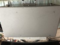
I bought for a few tens of euros, a long time ago, a Teac VRDS 9 CD player, described as non working. Didn’t know what was wrong with it. All I knew was that the device came from Japan to my seller, broken. D)It didn’t light on. Period.
I initially bought it for its mechanics (Teac CMK 4,2), being the same than the one used in my Krell KAV 300CD, in case I should replace it…
Recently, I decided to lean on it and try to figure out what could be faulty. I often read it’s a good drive, and I like my machines better when they are fully functional. I'd like to be able to use it as a drive someday...
I quickly saw that
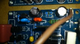
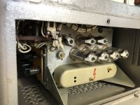
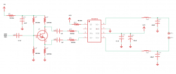
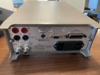
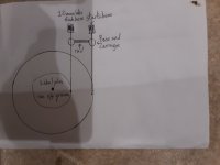
no voltage was available, right after the transformer. No secondary winding was delivering anything. So I went onto the primary windings and measured
no resistance between pin 4 and pin 5 (pin 5 responsible for 230V operation). Other trouble, the (internal - thermic)
fuse seems broken. It should be between pin 1 and pin 2, as on the schematics, but no continuity between the two pins.
Then my thought is: for a reason that can be discussed, the wire that goes from the 120V input (pin 4) to the 230V input (pin5) broke, current delivered rose, temperature too and the fuse broke (maybe the other way round?).
Could I be right?
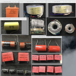
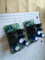
Then, I face this problem: as it is very unlikely that this transformer can be repaired, I’ve got to find a way to make the different voltages (AC) brought normally by the secondary windings available for the power PCB.
As I can’t read anything on my DMM out of the 10 different secondary windings since the 230V input is unavailable, I thought I could try this: have a 120V source to feed the 120V inputs of the transformer (AND shunt the pins 1 and 2 to
replace the broken fuse so that continuity is OK from 1 to 4,
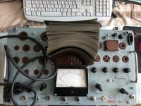
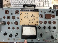
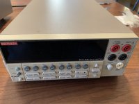
if it is safe enough). Just during the time necessary to read the voltage out of each one of the secondary pins. A Variac could do, probably. Though I don’t have a Variac, I can borrow one.
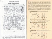
Then I’d find the adequate transformer (or transformers if necessary) to provide the necessary voltages to the Power PCB. Unfortunately they do not figure on the schematics, and the reading of the Power PCB schematics doesn’t allow me to guess them precisely (maybe some experts can do that but I’m not an expert…).
So, briefly:
- does someone know the normal voltage values out of this particular transformer? (9 different values, pin 5 is a ground)
- Or can someone who owns a Teac VRDS 9 take the corresponding measures from his own player?
- Or can someone give an idea/advice/method to help me measuring these values?
Thanks for reading, and even more for help if possible. I join a small drawing taken from the schematics.
Of course I can provide all schematics I have and pictures too.
Have a nice day/evening
😉


 Hello everybody.


