Hello everyone.
Didn't know exactly where to post this thread (as it is about power supply/transformer), so excuse me if it's not the right place.
I bought for a few tens of euros, a long time ago, a Teac VRDS 9 CD player, described as non working. Didn’t know what was wrong with it. All I knew was that the device came from Japan to my seller, broken. D)It didn’t light on. Period.
I initially bought it for its mechanics (Teac CMK 4,2), being the same than the one used in my Krell KAV 300CD, in case I should replace it…
Recently, I decided to lean on it and try to figure out what could be faulty. I often read it’s a good drive, and I like my machines better when they are fully functional. I'd like to be able to use it as a drive someday...
I quickly saw that no voltage was available, right after the transformer. No secondary winding was delivering anything. So I went onto the primary windings and measured no resistance between pin 4 and pin 5 (pin 5 responsible for 230V operation). Other trouble, the (internal - thermic) fuse seems broken. It should be between pin 1 and pin 2, as on the schematics, but no continuity between the two pins.
Then my thought is: for a reason that can be discussed, the wire that goes from the 120V input (pin 4) to the 230V input (pin5) broke, current delivered rose, temperature too and the fuse broke (maybe the other way round?).
Could I be right?
Then, I face this problem: as it is very unlikely that this transformer can be repaired, I’ve got to find a way to make the different voltages (AC) brought normally by the secondary windings available for the power PCB.
As I can’t read anything on my DMM out of the 10 different secondary windings since the 230V input is unavailable, I thought I could try this: have a 120V source to feed the 120V inputs of the transformer (AND shunt the pins 1 and 2 to replace the broken fuse so that continuity is OK from 1 to 4, if it is safe enough). Just during the time necessary to read the voltage out of each one of the secondary pins. A Variac could do, probably. Though I don’t have a Variac, I can borrow one.
Then I’d find the adequate transformer (or transformers if necessary) to provide the necessary voltages to the Power PCB. Unfortunately they do not figure on the schematics, and the reading of the Power PCB schematics doesn’t allow me to guess them precisely (maybe some experts can do that but I’m not an expert…).
So, briefly:
Of course I can provide all schematics I have and pictures too.
Have a nice day/evening 😉
Didn't know exactly where to post this thread (as it is about power supply/transformer), so excuse me if it's not the right place.
I bought for a few tens of euros, a long time ago, a Teac VRDS 9 CD player, described as non working. Didn’t know what was wrong with it. All I knew was that the device came from Japan to my seller, broken. D)It didn’t light on. Period.
I initially bought it for its mechanics (Teac CMK 4,2), being the same than the one used in my Krell KAV 300CD, in case I should replace it…
Recently, I decided to lean on it and try to figure out what could be faulty. I often read it’s a good drive, and I like my machines better when they are fully functional. I'd like to be able to use it as a drive someday...
I quickly saw that no voltage was available, right after the transformer. No secondary winding was delivering anything. So I went onto the primary windings and measured no resistance between pin 4 and pin 5 (pin 5 responsible for 230V operation). Other trouble, the (internal - thermic) fuse seems broken. It should be between pin 1 and pin 2, as on the schematics, but no continuity between the two pins.
Then my thought is: for a reason that can be discussed, the wire that goes from the 120V input (pin 4) to the 230V input (pin5) broke, current delivered rose, temperature too and the fuse broke (maybe the other way round?).
Could I be right?
Then, I face this problem: as it is very unlikely that this transformer can be repaired, I’ve got to find a way to make the different voltages (AC) brought normally by the secondary windings available for the power PCB.
As I can’t read anything on my DMM out of the 10 different secondary windings since the 230V input is unavailable, I thought I could try this: have a 120V source to feed the 120V inputs of the transformer (AND shunt the pins 1 and 2 to replace the broken fuse so that continuity is OK from 1 to 4, if it is safe enough). Just during the time necessary to read the voltage out of each one of the secondary pins. A Variac could do, probably. Though I don’t have a Variac, I can borrow one.
Then I’d find the adequate transformer (or transformers if necessary) to provide the necessary voltages to the Power PCB. Unfortunately they do not figure on the schematics, and the reading of the Power PCB schematics doesn’t allow me to guess them precisely (maybe some experts can do that but I’m not an expert…).
So, briefly:
- does someone know the normal voltage values out of this particular transformer? (9 different values, pin 5 is a ground)
- Or can someone who owns a Teac VRDS 9 take the corresponding measures from his own player?
- Or can someone give an idea/advice/method to help me measuring these values?
Of course I can provide all schematics I have and pictures too.
Have a nice day/evening 😉
Attachments

I tested the transfo with a variac and its primary winding(s) is (are) dead. Try to open it if I can to attempt a temporary fix. But the surest solution is to "guess" the secondary voltages from the circuit schematics... I keep you informed.
And if a VRDS's owner is willing to measure the voltages from his machine, I'm OK 😉
Thanks for reading.
And if a VRDS's owner is willing to measure the voltages from his machine, I'm OK 😉
Thanks for reading.
transformers often go bad because downstream parts such as diodes, caps, etc on the secondary side have shorted. I would test those parts before connecting up a replacement transformer and having it fail too.
Thanks for the input, tincanear. That's a good reason to kill a transformer, you're right.
In the present case, I'm pretty sure that the person who received this machine from Japan tried to make it work here in France (230V). There was a strap soldered (badly, not a nice soldering) between the #1 pin and the #5 pin -as it is meant to be done, by reading the schematics. BUT he FORGOT to unsolder (or cut) the 100V strap (specific Japanese market for sure). You can imagine what can happen when the guy plugged it and pressed the power button... The whole primary windings and the fuse must have made some light. Bad news.
Actually, I had the transformer tested yesterday by a friend who's got a Variac and it's confirmed that the transfo is dead, on its input side. I just opened it tonight and unfortunately, the primary windings are the inside windings. Not sure to have the courage to take all the secondaries out, make a new winding for the primary etc. But maybe I'll try this.
I started yesterday, from the schematics, to determine the different voltages out of the transfo. For now, I'm pretty confident that there are 9V, 30V (around) and 15V-0-15V pins. I'm unsure about the pins 7 and 9 which go to the fluorescent tube display, because I can't find any information about it (written FIP10YMB on schematics and FIP10YM8 on the parts list). Could be 5V as well as 40V, difficult to determine right now. I'll post the drawing when it's done.
I go on searching 😉 Good night.
Last edited:
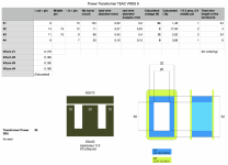
I dismantled the transformer. And I read the schematics. I can now see what voltages are produced by the transformer. It's really classical :
So now I've got several options:
Correct me if I'm wrong 😉
- pins 15-6: 0-24V
- pins 7-8: 0-9V
- pins 9-10-11: 12V-0-12V
- pins 12-13-14: 2V-0-2V
So now I've got several options:
- find a transformer from which I'll keep only the primary windings, then rebuilt the secondaries around it
- build a totally new transformer from scratch
- find off-the-shelf transformers (probably 2 maybe 3) and adapt the PCB to host the new components. There's room enough it I do it right.
Correct me if I'm wrong 😉