Inverted woofer horn box.

I'm from Brazil, and here we have several styles of boxing in different states of the country. And in the Northeast region of the country, the 15-inch inverted speaker horn box is widely used, in various types of systems or channels, with a 60cm box; 50cm; 1m (23.622 inches; 19.685; 39.3701) of horn, and 32 liter liter housing, varies from project to project and housing developer.

!I wanted to know what program I can design them!

There is a box that has the DUCT, right triangle with rectangle. (here in Brazil we call the air passage a duct) And I managed to make the square area of it, but I don't know if it's right!
The math I did was this: I multiplied the sides of the right triangle and divided by 2, and the sides of the square multiplied. Example: 12cm X 12cm= 144 ÷ 2 = 72cm².

Square: 42cm (width) X 7cm (height) = 294cm².

Once you have these 2 results, add the 2 = 366 to the area of the 2 together. I don't know if that's how I calculate. I used centimeters, but you can convert the measurements you use and test.


280226900_553559782792815_5060940365466760805_n.jpg
281576571_151960863991541_7093215293456710717_n.jpg
281164718_703860964165052_4218062560994075332_n.jpg
281391419_336885671718328_2367686088173427283_n.jpg

BM64 Bluetooth module help

I'm having some difficulty getting a Microchip BM64 bluetooth module up and running. It's soldered to a breakout board and powers up but never shows as a com port or usb device. It's also not discoverable. The datasheet says EAN should be low and P2_0 high for flash application mode. It says these pins have internal pullups but EAN reads 0.3 volts when left floating while P2_0 reads 3.3 as expected.

On powerup both leds flash 6 times and then led2 stays on for several more seconds before going out. Trying all the combinations of P2_0 and EAN never change the behavior. Neither does holding the button for any length of time. I can see the factory settings needing to be updated via the software but no usb device is ever registered. Below is my schematic. Anyone have any experience with this?

Attachments

  • BM64_schematic.png
    BM64_schematic.png
    61.2 KB · Views: 274

FS: PCBs to build an active crossover for Subwoofer and Sattelites (4th order)

I have PCBs to build an active crossover for Subwoofer and Sattelites.
The crossover is 4th order and includes Linkwitz transforms in both LP and HP sections.

The schematic of the circuit and the PCBs are shown in the photos below.
I will provide also the PCB assembly guide.

The cost for 2 pcbs that are needed for a stereo system is 32 Euros (shipping is included).

If you are interested send me a message.

Attachments

  • Αctive crossover schematic.png
    Αctive crossover schematic.png
    127.1 KB · Views: 461
  • Αctive crossover PCB.jpg
    Αctive crossover PCB.jpg
    476.4 KB · Views: 432

Weird HeadAmp Names

I recently build a diystore Whammy. It's a very good kit, an amplified straight wire, and 25W class A. I like the way it looks and sounds.

But Spring cleaning had some dusty headphone amps... the Edifier which means to instruct about morality .. like a preacher. Next there is Fubar III MK II DAC/AMP. I guess firestone-audio choose that product name so they would not have to search for already in use.

The Edifier HA11 arrived on slow boat from Asia. It had a 5532, a couple of 78/79 regs, and 9vdc power pack. It would randomly break into high-frequency oscillation. Edifier still has audio products but not headamps.

The Fubar3 has relays (discolored from heat), transistors, a generic audio opamp, and a DAC board. It runs from a 24vdc wall wart. It still works but sounds unremarkable. It has an intense blue LED which I covered with glue. High intensity LEDs are a pet peeve of mine.

Attachments

  • StrangeAmps.jpg
    StrangeAmps.jpg
    43 KB · Views: 99

FS: Satori MW16P-8 , SB29RDC in UK

Bought these a couple of years ago new for a project that never happened...! Only mounted once, stored since. In original packaging.

One pair SB acoustics Satori MW16P-8 midwoofers £140 + 10 postage
One pair SB29RDC-C000-4 tweeters (will sub for the Satori very well) £45 + 5 postage

Buy both together for £170 + 10postage. I will go halves on PayPal fees. Thanks!

1652862330955.png

1652862386569.png

Avel vs antek toroidal or else?

Looking to spend good money on a properly made trafo. Im in korea and the ones wound here hum mechanically, which i understand is from deficient windings.

For trafos that wont have this issue Ive found antek but the shipping cost to here is $90. Avel, carried by partsexpress, is only $30 shipping but id like to ask if it'll be as good as antek. Thanks

Alpair 10.3 bass reflex

OK I bit the bullet and took advantage of the Madisound sale on a pair of Alpair 10.3 m. Lucky me I've got a pair of boxes made out of some marble like material that I can repurpose for these. The box material is .5 inch and out side dimensions are 10x10.75x12. Looks like probably 16 liter net interior. My plan is to use this in my office without subwoofer. I intend to line the interior with a combination of butyl and felt. No idea if I should put any stuffing in there or not. From what I have read bass reflex should work well and the driver and port would bring the volume to just about 15 liter. But what port size? I am thinking to get the dual flare precision port as I have read the flares will limit or even eliminate chuffing. Considering that once in awhile I like to crank it up would anyone out there have suggestions for port sizes? 2" x 6" seems a good match for this application. But I'm sure there are others with more knowledge than I regarding ports and tuning. Also any thoughts on front, rear, or bottom firing? Placement in the office is flexible enough I could do any of these. Your comments are welcome. 🙂

Volume pot quality control

In making my preamp i often find volume pots that have stereo balance issues.

One channel is louder than the other until the pot is turned past almost half of its rotation.

Theyre all log curves and ive even had alps blue velvet with this issue. And its not an excessive gain issue. Ive tuned my whole system against that. (Preamp x3, amp x15)

My question is how do you weed out these pots? Ive put my multimeter to them but cant tell whats going on. Maybe build a test jig?

Tonearm parts

Any tonearm DIYers out there? I'm looking to find where to get those small pivot points (usually with lock nuts) found in most gimble type tonearms. Other than sourcing from old arms, which may or may not be worn or damaged. I have few jewel bearings I would like to try. I don't know what other device would use them...gauges, clocks, medical instruments?

Tube amplifier power supply

Hello

This is my first post on this forum. I'm not an electronics worker just a hobbyist. I know English at a basic level, so please be understanding.

I would like to introduce you to a tube amplifier power supply that I am currently building. All modules are already running and tested.


1. Transformer soft start.
2. Everyone knows
3. A 12 V auxiliary voltage power supply and fans' power supply.
4. Chokes.
5. Rectifier for preamplifier and tone regulator.
6. Rectifier of the right channel amplifier.
7. Rectifier of left channel amplifier.
8. Rectifier start - "controller".
9. Triple adjustable voltage stabilizer (430 V; 430 V; 260 V).
10. And everyone knows again.
11. Tube heater power supply 6,3 V with soft start.

The next step that awaits me now is to pack all these modules into one housing with two fans.

Sample housing.
Obudowa PESANTE 2U - 1NPS02400N - panel 10mm - CZARNY - Sklep modushop.pl

Sample fans.
NF-A6x25 FLX

If the topic will interests you I will be happy to provide details.

Jurek.

F5_XT

Hello,

Nice to be back.... A long time ago in this galaxy I lost the F5X from Patrick... I had to move, and did pack all my projects...; 14 years later 'I'm back'...
and be gentle it's my first try with EasyEDA to draw a board... I hope I didn't make any mistake(s). I will just make a pair of boards to build 2 mono-blocks.
I decided to start with a quarter of the schematic and replicate it 3 times to get to the final version. It's just a thread to share the evolution of the project!

F5_x_EasyEDA | Final Version | Allan Dupont | Flickr

Alain.

I'd like to rename the thread 'F5-XT' following the advice of EUVL 😉

For Sale Valve DAC (DSD-only variant) PCB + Transformer

Too many projects, too little time. I decided not to build my Valve DAC (DSD-only variant).
Selling PCBs and suitable R-core transformer.

Info about project in thread Valve DAC from Linear Audio volume 13.

  • DAC PCB (all SMD parts in front/back of the circuit board installed)
  • Filter PCB (pair)
  • R-Core transformer, never used (Primary 235V, Secondary 250V, 2x15V, 9V, 6.3V)

Price: 300 225 AUD + shipping.

Attachments

  • PXL_20220306_023550921.jpg
    PXL_20220306_023550921.jpg
    328.1 KB · Views: 294
  • PXL_20220306_023657292.jpg
    PXL_20220306_023657292.jpg
    279 KB · Views: 297
  • PXL_20220306_023941252.jpg
    PXL_20220306_023941252.jpg
    519.8 KB · Views: 309

parts identification SMPS (switch node power supply) with Class D amplifier

Good day. I am working with a switch mode power supply HYS3C210-CS for a Class D amplifier of a MOnster HD active speaker which has the same theory of class d amps used in cars , the only difference is that it uses a switch mode power supply. The power supply had blown MOsfet (CS1N60) which damaged the PWM controller WS3252 and some resistors and ceramic caps. I had the values of the other blown parts except for the C25 (ceramic capacitor) as shown in encircled with red in the diagram I got in one forum. Can anybody suggest which SMD ceramic capacitor i can use. Thank you in advance.
HYS3C210-cs.jpgHYS3C210-CS Power supply.jpg

Tapco 4400 US plug to UK plug

Hi! I have a Tapco 4400 with a 110V US plug and would like to follow the conversion from the service manual to convert it to a 240V EU/UK plug. The conversion is straightforward except for the fact that I have an additional jumper as highlighted here. I'm trying to follow the schematics but they aren't very clear.

Attachments

  • Screenshot 2022-05-17 212858.png
    Screenshot 2022-05-17 212858.png
    116.8 KB · Views: 95

Multiple Microphones

Before all, please, note : some audiophiles may not prefer to parallel microphones because, although made by the same manufacturer and processes, there are tolerances which may lead to slight non linearity. I hope this is negligible.

I have made a multiple microphone with sixteen Electret Condenser Microphone capsules.

I still wait for a 500K dual potentiometer which has been ordered. The device was tested without such with direct wire connections instead.

The document is not finished, there are more explanations to be made and pictures, which would probably be made once the dual potentiometer is installed as well as labels.

The document will be updated.

I would like to publish this document now, although not fully completed, because the project has been an obsession and a dream which I have been able to make a reality.

Here is the document :

Multiple Microphones - Google Drive

Rockford Fosgate Punch P1000x2 - Blown Output FETs

Just got an RF P1000x2 in on a trade, 1 output FET blown on each high/low side, removed all output FETs, Powers on blue light only/not in protect (red/left LED on while rail charges then goes off) I get power supply switching up to Rectifiers, no switching on any of the output Gates (which is the low side FETs between the 2 groups? IRF6218 and IRF3415 are what’s used, 4 each per side per channel)

While on it seems to idle normal at about 1.8a but then climbs by .10a until it gets to about 3.5a then protect kicks on, takes about 60 seconds from power up til protect kicks on. I also noticed negative rail will not discharge when power is turned off (I always check rail voltage constantly, habit now lol) I have to discharge it myself, positive rail discharges as it should.

I am not familiar with Fosgate amps so I installed new FETs, ran a 50hz signal @ 1vpkpk just to see what it did and it acts the same, comes on clean, switching up to rectifiers, idle current climbs but I notice output FETs are getting hot, way hotter then it should, I kill power soon as idle gets to about 2.8a because of how how FETs were getting.

Only difference of symptoms when FETs installed that I can tell is they heat up. Any help for a starting point with this amp would be GREATLY appreciated, just a few pics for reference included, unmarked FETs on left was the problem channel, replaced all 8 vs just the 1+1 that blew) the blowout was internal on those 2 as well, no Big Bang or magic smoke even that I can smell. I’m going to start probing everything everything with my multimeter, etc to see if I am randomly find any bad components in the meantime, always have good luck when I do and I learn some so 🤓

Thank you!

P.S. climbing idle has me weary of keeping it on for more then 30/45 seconds at a time, the one time i let it run until protect kicked on it wouldn’t power back up for a lil bit, I’m assuming it may be a heat issue, and I do not have a thermal imaging camera yet :/ (seeking a used thermal imaging unit if anyone has one for sale) 🖖🏼

Attachments

  • F071ABCC-1083-471E-B256-604E2431EBC5.jpeg
    F071ABCC-1083-471E-B256-604E2431EBC5.jpeg
    623.7 KB · Views: 208
  • E5ED78EF-9C2E-4D8C-AA41-05E994C1DE75.jpeg
    E5ED78EF-9C2E-4D8C-AA41-05E994C1DE75.jpeg
    573.9 KB · Views: 208

Web Browsers

Why do all the browsers seem to suck these days?

Chrome won't work with Twitter now so I moved my passwords out of Google and into Bitwarden.
Yes, I know Adblock is blocking some of Twitter, but first off: it doesn't work if I turn it off, Secondly: If your site doesn't work with ad blocking, I won't use your site.
If I go to a news site that has a "paywall", I just disable Javascript for that domain.
1651858303456.png

Brave can't set actual location and crashes if you click a "Google Pay" button.

Firefox can't set a speed dial as it's home page, and extensions like mouse gestures don't work on built in pages (can't open a new tab with a mouse gesture on the home screen).

Opera is annoying and unstable last I used it.

Edge is MS and I'm just not interested.

Epiphany kind of sucks.

So now I'm running Vivaldi and so far so good. They even have an Android version so I've created a Vivaldi account to sync devices... Maybe I'll finally be able to have ONE browser instead of five...

miniDSP IIR filter phase/delay questions

ALL,
So I'm learning that IIR filters cause an electrical phase shift equal to their analog counterpart and you can compensate for that using delay...right? If that be the case, then some questions based on this system: sub woofer= LR24dB Low pass @ 90Hz___woofer=LR24dB HP@90Hz & LR24dB LP@650Hz___planar mid/tweet=LR24dB HP@650Hz
1) If I have a LR 24dB Lo Pass 90Hz on my sub and a LR 24dB Hi Pass 90Hz to my woofer, that would be a 180deg shift that would delay the signal @ 90Hz by 5.5ms...right? So I'd add 5.5ms delay to woofer, yea?
2) A 180deg phase shift would delay the woofer signal by .75ms at 650Hz...if I've delayed the woofer's signal by 5.5ms to "meet" the sub, is that cumulative to the tweeter's overall delay for a total of 6.25ms?
3) On top of all this, is the delay for time alignment added in as well?
For reference, my sub is a down firing 18 in an aperiodic enclosure. The OB 15" woofer Voice Coil is about 5" forward of the center of the 18. The OB planar mid/tweets are about 3" in front of the 15 VC.
Thanks for the lessons to come!

Attachments

  • SPEAKERS.png
    SPEAKERS.png
    6.1 KB · Views: 138

Rear Mounting Driver Tips?

Good day everyone, hope y’all are well

What are your guys’ best practices or suggestions for rear mounting drivers to a baffle?


I’m specifically having a bit of a hard time trying to read mount an SB17NBAC to the rear of my baffle, as I’ve noticed the driver frame has a bit of a curved lip to it (as opposed to being a totally flat frame) - would anybody have any tips for this scenario?


Thank you guys in advance

Experiments with GRS PT6825-8 Box Volume

Long backstory read if you want to know why I'm doing this experiment.
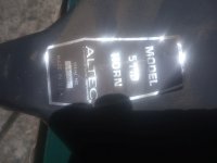
I’ve been watching PS Audio’s Paul McGowan’s videos for some time now and have seen bits and parts of the development of the current FR30 speakers. It turns out they are basically using a BG Neo 10 for the midrange and Neo 3 for the tweeter. This is interesting because there are currently some similar drivers available for purchase at parts express under GRS that are relatively cheap compared to their BG counterparts. I’d like to build a similar speaker that uses these planar drivers but have no idea how to construct the box since they do not have TS parameters like conventional drivers. These are some experiments that I’ve done to try and learn about optimal box size.

Testing Setup

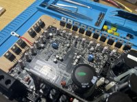
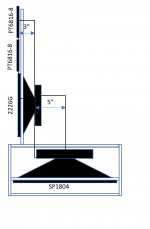
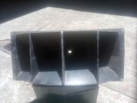
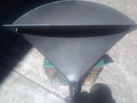
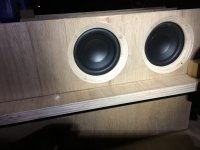
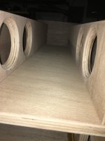
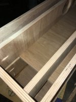
A basic test enclosure was built using some scrap wood lying around and was used to experiment with box volume to see how it affects the parameters above. The size of the box is somewhat random, and there is no real reason for its initial size and volume aside from a shape that I would reasonably expect to incorporate into a completed speaker.
It measures 5” x 10” x 12”, and the driver is mounted in the front with a foam gasket to prevent air leaks.
To adjust the size of the box, I have a panel with a foam gasket parallel to the driver that can shift forwards and backward to adjust the internal volume.
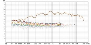
All measurements were taken from 1 Meter away, at a fixed volume using REW, and then 1/12 smoothing was applied to FR graphs. (Just to make it a bit easier to read without losing too much detail)

Baseline Test: Full Volume
No internal Wall, internal Volume of 600" cubed

Frequency Response
Full Volume.jpg

The frequency response of the driver in the box with full volume doesn't look great. There are two large peaks in the 900-2khz region that can cause sounds to be shrill.

Distortion
Distortion full Volume.jpg

Since this is a planar driver, distortion values were quite low. In the usable range from 300hz to 6khz, the THD is below 1% at its highest and there is no audible distortion past 500hz

Waterfall Plot
waterfall Full Volume.jpg


Also as expected of a planar driver, the decay time is very fast. No real issues with stored energy here. We do once again get to see the large volume peaks at 900hz and 2khz.

3/4 Volume
The box now has an internal volume of 450" cubed.

Frequency Response
0.75 Volume.jpg

Compared to the previous enclosure with full volume, this has a slightly more linear response.

Distortion
distortion 0,75.jpg

The total harmonic distortion appears to be lower than the full volume by 0.3% on average across the useful range from 300hz to 6khz.

Waterfall Plot
Water fall 0.75 voluime.jpg

I am not able to see any outstanding differences in the stored energy. the planar drivers are still just as fast as with the full volume.

1/2 Volume
The box now has an internal volume of 300" cubed.

Frequency Response
0.5 Volume.jpg

Reducing the enclosure size seems to once again have smoothed out the response very slightly. Some of the dips around 1.4khz have filled in and some of the smaller peaks above 3khz have been reduced.

Distortion
0.5 distortion.jpg

The total harmonic distortion does not seem to have any significant differences compared to the 75% volume measurement.
0.5 waterfall.jpg

Once again no significant differences to the waterfall plot.

1/4 Volume
The box now has an internal volume of 150" cubed.

Frequency Response
0.25 Volume.jpg

Compared to the box with half volume, the quarter volume box seems to have a few deeper dips and higher peaks.

Distortion
0.25 distortion.jpg

The total harmonic distortion has increased by about 1% across the usable frequency range from 300hz to 6khz compared to the box with 1/2 Volume.

Waterfall Plot
0.25 waterfall.jpg

There's a pattern, nothing to see here.

Minimum Volume
The divider board was pushed as close to the back of the driver as possible. Not sure exactly what the volume is, but there is barely any space behind the driver.

Frequency Response

Minimum Volume.jpg

The response for the minimum volume is quite interesting. It appears that across the usable spectrum the response is the flattest out of all of the previous measurements. However, there is a steep rise in SPL at around 800hz. One could speculate that due to the small width of the baffle, the increased volume after 800hz is a result of baffle gain. IT could also be a result of other causes.

Distortion
distortion min vol.jpg

While the response of the box and driver has become more linear, the total harmonic distortion has increased in a few areas. The total harmonic distortion increased significantly between 300hz to 700hz giving an average of 3%, while the remainder of the frequency range kept a fairly low average of 0.3% THD. These problem areas may be a result of having a hard surface parallel to the driver and also being so close to the driver. the back wave of the driver may be bouncing back and affecting the sound produced by the front of the driver. if you have other theories on why this may be the case, feel free to let me know.

Waterfall Plot
waterfall min volume.jpg

Still no appreciable differences.

Conclusions
The smoothest frequency response across the entire frequency range was produced by the box with of 300" cubed volume. The best distortion characteristics were also exhibited by the 1/2 Volume box. However, in the upper frequencies beyond 800hz the minimum volume box performed best. The box with minimum volume had some strange interactions and produced both the highest distortion values and lowest distortion values, perhaps other methods of damping the box may help to solve those issues and make it a viable option. In terms of the waterfall plots or stored energy, in each scenario, the drivers seem to have no issues staying fast, and dissipating energy instead of ringing.

Maybe in the next experiment, I'll play around with stuffing the box with various materials to see how they affect the driver's response characteristics. Currently, the materials I plan on testing are Polyfill, Rockwool insulation, Felt, and Melamine Foam.

PS.
First time making a post on DIY Audio, and a very new speaker builder. There are a lot of things that I don’t fully understand yet and I’m doing my best to explore and learn. If anything I’ve written is misinformation or conducted improperly, please feel free to let me know, I’d love to get as much input and feedback as possible. I’m still pretty new in the audio space and as such, can’t say that my ears are trained and skilled at picking out nuances like other audiophiles might be able to. That’s why this post is only going to contain objective measurement information. I’m sure subjective testing is very important as well, but I don’t think I can do a good job of that as of now.

Attachments

  • 0.25 distortion.jpg
    0.25 distortion.jpg
    72.3 KB · Views: 155

Loudspeaker measurement paper by Czerwinski and others

I recently learned of a company called Cerwinski Labs. I didn't make the immediate connection, but soon learned it was started by Gene Czerwinski, founder of Cerwin Vega. Googling around to see what info I could find about the company, I came across this paper published by Czerwinski and a few others. I started to read it but it's all a bit over my head. I'm not looking for help understanding anything, I just figured I'd share it. Maybe some of the more apt minds on the forum might find it interesting

Attachments

  • Thank You
Reactions: GM

DIY shielded signal cables

Hi!

I want to make my own shielded RCA signal cables, short lengths from DAC to preamp, and from preamp to poweramp. There are probably many threads discussing this, but I am having trouble finding appropriate lengths and deciding cable type.

Can anyone help? Where to buy, and what cable construction types and conductor material is the best way to go? I am thinking cooper, but should I go coaxial or what is most cost effective solution?

It would be nice if it could also be used for internal amp signal wiring.

I appreciate any advice.

Regards,
Andy

Upgrading Philips DVD 963 SA

In this thread I would like to share knowledge on upgrading the Philips DVD 963 SA (CD-upsampling / DVD / SACD) player.

This player is interesting because of its rich list of features and its low price.

This price has also led to some serious shortcomings, as observed in the other thread: http://www.diyaudio.com/forums/showthread.php?s=&threadid=10224

Here I will start with posting some links and some personal experience with this player.

Lucas

2.1 Pyramid speakers with Arylic Amp 2.1 board

Hi,
A quick view on my latest project based on the Arylic DIY board (AMP 2.1). An evolution of the mono version (see the article here) towards stereo mode.

Twin pryamids (well, not real twins...) with the master including the Sub woofer (Tang Band W5) + AMP 2.1 board, and the small one (right channel) with only the medium and tweeter, for an optimisation of the volume. They are separated by several meters to get a good stereo mode.

As the Sub frequencies cannot be localized by our human ears, even if located on the left, the bass seem to come from "everywhere".


1652800889206.png
1652801975870.png


The design is based on a very powerfull Arylic 2.1 board (2x50W + 1x100W sub), supporting WiFi, Airplay, Spotify Connect & Bluetooth 5.0:

1652800816284.png


Note that I used the DSP integrated into the Arylic Amp 2.1 in order to:
1) send only the bass to the sub channel with a low pass filter
2) Remove the bass signal sent to the medium & tweeter via a passive filter of each channel (cut at around 3k)
3) Adjust the equaliser for each channel in order to correct the passive filters/wood boxes and speakers impact on the signal linearity.

The result is quite cool and the volume generated overal quite impressive! The sound remains clean even when pushing the volume to the max, with the Class D amplifiers.

Hoping it can give you some ideas for your next DIY project 🙂

For Sale Amp Camp For Sale Two Weeks Old

I purchased this amp thinking my preamp would be able to drive it to a reasonable level but it won't Professionally assembled. Mint Condition
It has about 2 hrs use on it. Thanks Pictures available. gwognibene@cox.net

Attachments

  • 5watt3.jpg
    5watt3.jpg
    27.2 KB · Views: 167
  • 5 watt4.jpg
    5 watt4.jpg
    29.4 KB · Views: 156
  • 5watt2.jpg
    5watt2.jpg
    35 KB · Views: 165
  • 5 watt 1.jpg
    5 watt 1.jpg
    57.7 KB · Views: 157

Wharfedale W12/SFB vs W12/RS/PST

What are the main differences in terms of Thiel specs? W12/SFB was used in the SFB/3, while W12/RS/PST, incorporating the polystyrene diaphragm, was used in later models.

I am specifically wondering if W12/RS/PST can be used in a SFB/3. Wharfedale's own docs from the late 50's and early 60's seem to suggest that W12/RS/PST was the improved version of the older W12 (which may have included the SFB version). Thanks!

Well, this is getting serious

The rolling shutdowns are starting to have a serious toll on the electronics industry. I'm in the middle of buying a kit of parts for a CNC controller and it has taken me days to locate small quantities of some items. The normally cheap Chinese sources are price gouging to the tune of 5x the normal prices, especially on automotive related components.

If you thought finding obscure bits for audio builds was challenging, try finding an LM4801-Q1 ideal diode. This part is in current high volume production at TI and yet delivery to the usual wholesalers isn't expected until May 2023. Similarly the ZXTR2012Z-7 regulator has become unobtainium. These are parts for which there is no substitute or second source.

The one that surprised me the most though was the ATXMEGA192A3U micro. Evidently Microchip are also wedged. I managed to find ONE ATXMEGA256 at 4x usual retail and grabbed it without hesitation in order to at least test the protoype.

So for the next year this project is on hold, tying up thousands of dollars. It's the end of the world as we know it.

FS: Electrocompaniet Amp & Preamp

SOLD

$150 - for both pieces; local pickup in Michigan preferred as they are heavy and would be expensive to ship.

This a preamp and amp combo from Electrocompaniet model Ampliwire IIa. First off - these will need some work and the amplifier is in non working condition and emits a loud buzz when the signal is applied. Visual inspection does not show anything burned out on the boards but trouble shooting and bringing this unit is far beyond my skills. These are fairly rare units and I think would be worth the effort to get them back to spec for the right person.

The preamp has a phono stage built in and the amp is 50 watts per channel with the first 5 watts being class A from what I could find online.

1.jpg
2.jpg
3.jpg
4.jpg
5.jpg
6.jpg
7.jpg
8.jpg
9.jpg
10.jpg

Repairing B&O Beogram 1800 turntable - wiring question

I am having an issue with my B&O Beogram 1800 turntable as the RCA leads induce static, as I move the RCA cables around I can hear lots of static. And I do have the ground wire properly attached to my phono pre. I have to place and lay the cables "just so" to minimize the static. I thought about rewiring new and better RCA cables leads which I believe I can pretty easily accomplish.

My question was regarding the fact that the the tone arm leads inside the turntable running the short distance to the signal board are just bare exposed wires. This is the first turntable I have ever dug into, do these bare tonearm signal leads pose a problem as well? Should they be sleeved or wrapped? Or are bare signal wires internally the accepted practice?

I wanted to ask here before I proceed with rewiring the RCA leads to see if I could/should do anything.

As always, comments are most appreciated.

Advice on removal of resistor in B&W DM110 crossovers?

I picked up a pair of B&W DM110 Loudspeakers some time ago and have had them apart for a restoration until just recently.


I replaced the electrolytic caps with poly, fitted banana terminals and have tidied up the vinyl wrap and grill connectors.


They're about to be re clothed.


Given B&W's reputation for quality HiFi I was very disappointed after an A B test with my Interdyn Model 212 Loudspeakers.


The B&W's sound dull and flat.


Not having the skill nor equipment to test and diagnose possible improvements I'm not sure how to go about improving the sound.


Given my experience of adding a resistor to the Interdyns I thought maybe I could experiment by removing the resistors in the crossovers.


Is it possible removing the resistors could improve the high notes?
They're Bennic 2.2 Ω sandcast resistors.


Also the larger of the 2 Inductors is a iron core type.
Don't know if this has a bearing.


Thanks Cliff

Add-A-Buffer Adapter boards (Your Op-Amp + BUF634A in a DIP-8 socket)

This board fits any single SO08 op-amp and a TI BUF634A buffer IC into a single DIP-8 socket!
(Op-Amp and BUF634A IC not included.)

Buy them here, or download the Gerbers and Eagle CAD files and have them made for you!


Useful wherever increased current drive and immunity to capacitive load is desired. (Headphone amplifiers, line drivers, active filters, equalizers, etc.)


The TI BUF634A adds a fast and powerful output stage to any op-amp. It is inserted into the feedback loop, essentially becoming a part of the op-amp itself.


BUF634A chips are available with or without a heat-sinking “power pad”, and the board is compatible with either. Vias through the PCB footprint conduct heat throughout the board.


I do not sell the ICs. Click here to search OctoPart.com for stock on these items.
BUF634AIDR (SO08 – No Power Pad)
BUF634AIDDAR (SO08 With Power Pad)


It’s also worth checking TI.COM for inventory; they are actually cheaper than most suppliers!

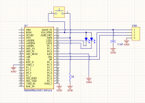
Adapter board next to standard op-amp. Note that the dimensions are 12.8mm x 12mm.
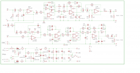
 Installed in a phono preamp.


Schematic
Note: Pins 1, 5 and 8 serve different functions on different op-amps, usually used for offset nulling or bandwidth compensation. The adapter board simply connects these pins through. If these pins are used in your application, you must determine if they will work properly with the op-amp you have chosen.


Bandwidth:​


Two methods of controlling bandwidth are provided on the board.


    1. The BUF634A’s bandwidth is adjustable from 35MHz to 210MHz, set by an SMD 0805 resistor tied between Pin 1 and Vcc. See datasheet for a graph of bandwidth versus resistance. Note that power consumption and heat dissipation rises with higher bandwidth.
    2. Pads for an SMD 1210 compensation capacitor are provided. The capacitor is connected from the op-amp’s output to the negative input. (From the op-amp’s output, not the BUF634A.) This gives increased negative feedback at high frequencies and limits the bandwidth of the op-amp. This is often done when replacing a slower op-amp with a faster one, to prevent oscillation or ringing. Recommended capacitors; Cornell Dubilier MC series Silver-Mica in SMD 1210 or 0805.

Compatibility and no-tech-support disclaimer:​


I have no control over how this product is used, and due to the infinite variety of op-amps and devices they my be installed in… I’m sorry, this product comes with no tech support. I cannot answer questions about the suitability of any particular op-amp to any particular device. This product may cause oscillation, instability, DC offsets, or other issues when used with certain op-amps, or certain circuits. Many factors contribute to a circuit’s stability, such as bandwidth of the op-amp, power supply layout, bypassing, and frequency compensation. It’s up to you to determine if your application is working properly.


See this helpful thread at DIYAUDIO.COM about testing op-amp circuits for stability.


Get boards for almost free:​


Yes, really! This is a semi-promotional item. Buying from me supports me and my site, or you can download the files and have them made for you. Here are the design files so you can order direct from a board house like JLCPCB or PCBWay. (No affiliation)


Eagles and Parts Libraries:
Gerbers:


You’ll also need the PCB pin headers. They are Preci-Dip part number 350-10-104-00-106101


Won’t people just copy the design, and maybe even sell it? Yes, they will. Please give me credit if you do. Some people will buy from me to support my business. It’s all good.


Assembly:​


This is very tricky SMD soldering! Five boards are included in case you screw one up.


Here’s how I do it, using a regular soldering iron. You may have your own favorite method that works. Hot air and solder paste will also work well, but be aware that there are some vias-in-pads that will absorb solder, so these vias should be pre-filled with solder.


    • Start by applying some flux to the all exposed pads on the board.
    • First, we’ll install the BUF634A IC. Add a blob of solder to one of the pads.
    • Align the chip and melt it down onto the pad
    • Solder the rest of the pins.
      Note: Some of the solder pads have vias through them, and they absorb solder, so make sure you use enough solder to fill the vias, and still have a nice solder fillet around the IC pins.
    • Soldering the thermal power pad: (if applicable) Flip the board over, and flow solder into the six vias drilled through the power-pad, until the solder soaks in and wets to the back of the BUF634A. Use enough solder to cause a slight mound to form.
    • Install the op-amp using the same method
    • Install the bandwidth resistor. See datasheet for values. For maximum bandwidth, simply form a solder bridge across the pads. For minimum bandwidth, leave it open.
    • Install the compensation capacitor. (If applicable)
    • Installing the pin headers: A 4-pin DIP socket was included in your order, to use as a jig to align the pins while you solder them. Insert the pin headers into the 4-pin DIP socket as shown.
    • Add a blob of solder to one of the pads for the pin-headers.
    • Add flux to all the pads for the pin-headers
    • Align the pin-headers precisely, and melt one to the pad. Solder all the pin-headers you can reach. There will be a few you can’t reach with the 4-pin socket still attached.
    • Remove the 4-pin socket and solder the rest of the pin-headers
    • Almost done! But that flux is a mess, and some flux is slightly conductive. Drop it in the ultra-sonic cleaner. (I use denatured alcohol in the ultrasonic cleaner and a water-soluble flux, both in the syringe and the solder wire.)
    • Done! You might want to check for shorts between pins on the ICs. You might also want to test your new opamp/buffer combo, in a simple circuit on a proto-breadboard before installing it into your precious equipment.

The Diyaudio Long Throw Array

For nearly two years I've been trying to figure out how to make a loudspeaker that has wide horizontal directivity and narrow vertical directivity:

https://www.diyaudio.com/community/threads/the-nightmare-before-labor-day.374570/

The subjective data seems to indicate that this beamwidth is ideal: https://www.audiosciencereview.com/...ootout-between-jbl-m2-and-revel-salon-2.1844/

qytbTUd.jpg


Something like the Danley SH-64 seems like an obvious choice, but they are HUGE. Thirteen cubic feet and 197lbs; much bigger than your average subwoofer. I appreciate the technology, but I don't need to hit 140dB in my living room.

The response and the beamwidth of arrays is CLEARLY IMPROVED by curving them, and the D.B. Keele CBT papers illustrate this really well.

So that got me messing around with various variations of curvature, crossover, and driver spacing.

After messing around for a while, I found that some of the best results can be achieved by using an array that's PHYSICALLY converging but ACOUSTICALLY expanding.

Let me elaborate on that statement. In a nutshell, a multi-way loudspeaker on a flat baffle will tend to have a wavefront that's curved. This is because the crossovers introduce a delay.

HDptMIn.jpg


For instance, here's a picture of the Snell Acoustics XA Reference, designed by @SpeakerDave. The crossover point is 250Hz for the woofers. The slope is something like 18dB per octave. This will tend to introduce a delay of about 3ms - or about forty inches!!! In the real world, the actual delay will depend a lot on the passive crossover configuration. Theoretically, a third order crossover introduces 270 degrees of delay (90 degrees for each order.) The net effect is that the woofer is delayed by about 3ms. (Sound travels 13.5 inches in one second, 250Hz is fifty four inches long, 75% of fifty four inches is 40.5 inches.)

yV3OtxT.png


After tinkering for a while in Vituixcad I began to realize that the baffle needs to CONVERGE in order to produce a flat wavefront. This probably seems counter-intuitive; the Snell baffle is flat. Why would it generate a curved wavefront? And the answer is in the passive crossover. A third order crossover at 250Hz (like in the Snell XA Reference) produces about 40.5 inches in delay! Due to the fact that the tweeter in the center of the array isn't delayed remotely as much by the crossover, the wavefront of the array is significantly curved. The wavefront isn't curved physically; it's curved by the crossover.

With that knowledge in hand, I began to tinker with WMTMW arrays, and manipulating the curvature of the loudspeaker baffle, to achieve beamwidths which wouldn't be otherwise possible.

For Sale Siemens E88CC Cca Grey Shields NOS/NIB

Selling my Siemens E88CC Cca. It has grey Shields and dates back to the early 1960'.

Tube is in perfect condition, has not been used, just tested for microphonics.

It's nearly impossible to find this tube in this condition.

Free shipping worldwide: price $220

Attachments

  • IMG_20220516_084732_1.jpg
    IMG_20220516_084732_1.jpg
    367.8 KB · Views: 104
  • IMG_20220516_084529.jpg
    IMG_20220516_084529.jpg
    351.9 KB · Views: 99
  • IMG_20220516_084153.jpg
    IMG_20220516_084153.jpg
    143.6 KB · Views: 111
  • IMG_20220516_084732.jpg
    IMG_20220516_084732.jpg
    372.7 KB · Views: 110

Recapping laser mechanisms (electrolytic age replacement)

I have a 24y/o Myryad MC100 that uses a CDM4 transport with a KSS240A laser mechanism. I'm starting to recap the power board but given the state of the MF amp's electrolytics, I was thinking if starting to recap the rest of the player.

The KSS240A has electrolytic(s) on it so I was wondering if anyone has replaced the caps and if there's any issues I would have be aware of?

Altec 511B (single) Sydney, Australia

PRICE DROPPED


Generally good condition Altec 511B for sale. I've owned it a long time with the intention of finding another for a project. Plans have changed.

$A250.

Can do contactless pickup if needed, fully vaxxed.

Check the pics. The brownish marks are some dust from storage I didn't wash off fully.

Can ship if needed but it won't be cheap.

Edit: I have a ton of other audio gear I'm going to list in the near future as I'm moving so keep an eye out.

Attachments

  • Altec 511B mouth small.jpg
    Altec 511B mouth small.jpg
    778.7 KB · Views: 171
  • Altec 511B throat small.jpg
    Altec 511B throat small.jpg
    305 KB · Views: 165
  • Altec 511B badge small.jpg
    Altec 511B badge small.jpg
    609.1 KB · Views: 167
  • Altec 511B top small.jpg
    Altec 511B top small.jpg
    852.9 KB · Views: 163
  • Altec 511B bottom small.jpg
    Altec 511B bottom small.jpg
    951.8 KB · Views: 158

39 hz 4 x4 “ compound/parallel qw pipe.

Attachments

  • D960488B-0D5B-4399-A3E5-8BB1F2BED671.jpeg
    D960488B-0D5B-4399-A3E5-8BB1F2BED671.jpeg
    367.4 KB · Views: 226
  • C6FFE731-4D9D-41B6-81E7-2DCEF1D228CB.jpeg
    C6FFE731-4D9D-41B6-81E7-2DCEF1D228CB.jpeg
    417 KB · Views: 214
  • 43195A5C-114B-49B5-B583-35A3C53E1015.jpeg
    43195A5C-114B-49B5-B583-35A3C53E1015.jpeg
    375.8 KB · Views: 203
  • B9A11E99-A0B1-42E7-8F23-2187842A05F7.jpeg
    B9A11E99-A0B1-42E7-8F23-2187842A05F7.jpeg
    380.7 KB · Views: 206
  • FBFD6AC4-A1D8-41F1-BBE5-F5C88E9AE90D.jpeg
    FBFD6AC4-A1D8-41F1-BBE5-F5C88E9AE90D.jpeg
    512.3 KB · Views: 228

5U4G minimum supply impedance, (cap vs choke input)?

What is minimum plate supply impedance all about? The 5U4G tube specifies a minimum of 75 ohms per plate for a capacitor input supply. But I'm doing up a choke input supply with: TOROID (full wave) --> 5U4 --> 15H --> 40uf. I'm assuming I don't have to worry about this parameter when doing choke input, correct? The reason I ask is because my transformer is a toroid and I know those have less impedance than a vintage EI transformer. Is the minimum supply impedance restriction specified for safety or longevity of the tube? I remember as a kid we had a TV set where the 5U4 would literally explode, happened twice, then dad junked the TV.

My toroid has 3.5 ohms primary DCR (with coils in parallel for USA 115v). And it has secondary DCR of 80 ohms (40-0-40 ohms). 40 ohms is way below the 75 ohms per phase in the data sheet. BUT the data sheet only lists minimum supply impedance for capacitor input PS. Final question... Am I okay using this 40 ohm toroid for a choke input supply since the data sheet doesn't mention this parameter for that topology?

https://frank.pocnet.net/sheets/127/5/5U4G.pdf

Bricasti M1 processor - modification.

Moved from another thread....

I have this dac (Bricasti M1) and I like it very much, but to my ears the treble (slightly) lacks ultimate resolution and sweetness compared with my other dacs. On bright and older recordings it can tend to be a little "unforgiving".

Taking a look at the pcbs's I noticed AD843 op-amps in the IV and buffer stages. These op-amps are not noted for audiophile qualities but they are advertised for high speed applications including 'high speed integration'.

In an effort to add some sweetness I decided to bias all of the op-amps into class A. I did this by adding a CRD with a series resistor from the op-amp output to the -ve rail. (4 per channel) I mounted them on the underside of the pcb so as not to deface the aesthetics. The resistor was used to set the v drop across the CRD to the mid point of the linear region, which for the specific 2mA CRD used was 8.5 vdc.

Because the op-amps are all paired from the diff outputs from the dac, I decided to batch test and match the CRD's to <1%, which was possible because I had a large stock on hand. I also found that the CRD's ranged in value from 1.7 to 2.3mA, but nominally 1.9mA.

I also tested the current sink regulation over a 3V range and it was a creditable 99.8%.

While I had the dac apart I also passed a cursory eye over the linear power supplies which are all discrete types using op-amps to generate references and with tip120/125 darlington output transistors.

I noticed that a 104 film cap had been installed across the bridge rectifier input (transformer secondaries) and another at the bridge output, but there was no series resistor with the input 104, so it obviously isn't an effective "snubber". This seemed odd, so I subsequently unsoldered one side and added a 330r resistor in series ( 2 per channel), though I didn't use the cro to check, from past experience those values are usually effective at damping any ringing.

OK, so how did it sound after this change you might ask?

Actually, I was very surprised to hear such a big change, because frankly, I wasn't able to measure anything substantial on the pc based analyzer. (distortion was already a low 0.001%)

However, the treble is now MUCH sweeter and more pristine than I could have ever imagined possible, and all of those bad old recordings are now very easy on the ear. It's now every bit the equal, and then some, of my Berkeley Alpha 2 in the treble and is easily the best overall and least 'digital' sounding of all my processors. I also now prefer to use the linear filter set rather than the minimum phase set.

It's worth noting though that I made two changes at the same time, so it's difficult to ascribe the contribution from each, but I'm assuming it's the 2mA of bias on all op-amps that's been the major factor.

I can't say that this same modification will be as effective for all op-amps, and / or in other implementations, but it's nonetheless worth experimenting with based on my personal experience.

Hello from Toronto! Aspiring DIY Speaker Builder

Hi Everyone! I'm Michael from Toronto, Canada. I'm a beginner speaker builder and novice audiophile. I've been lurking in the forum for a good few months now and decided I should start and participate in some of these really interesting conversations. A bit of background on myself, I started building speakers near the end of 2021 as a way to kill time during pandemic lockdown with no idea how deep this amazing rabbit hole really went. Maybe an interesting fact? I'm under 25 which makes me part of the minority age AFAIK.
The first pair of speakers that I built were modeled (very roughly) after the PS Audio FR30, but with very little real speaker-building knowledge. I think they sound great compared to anything else in my home or any of the other speakers in my friend's homes but my opinion of them will probably change as I build more speakers and learn new things.

Anyway just thought I'd say hi before I get involved, see you around!
4A706897-F7A8-4898-9F87-C799BA3A7AC4_1_105_c.jpeg

Speaker Power vs Amp Power

Hi,
I have combed the internet without an answer for the below and hope someone can give me an answer.

I am making a chip amplifier, LM6886 68W per channel, powered by a toroidal 28V 250W. The speakers I have are rated 8 Ohm, 250W, 8 Inch full range (+tweeter). My intension is to listen to (high) quality well balanced music at low sound levels, without distortion.

I have read - if the speakers have a much higher wattage that the amplifier then there will be clipping, sound will be distorted, sound will not be lively and etc. There are lots of answers about sound quality but no explanation to the reason. I'm searching for the reason for this quality drop. Can someone please explain; why does a higher watt speaker create sound quality issues.

Please your answers will quench my thirst for knowledge also consider buying (new) speakers.

MTX Thunder "elite style" 92001 resistor value

Working through this one, and pads R4082/R4087 have a single 3w resistor soldered between them. The resistor runs 300+F degrees and smokes slightly and is discolored and discoloring the board. I'd like to replace this resistor with a 5w. Off the board this resistor is measuring 7.8k, but looks like this is either a 10K or maybe even a 10/100/1000 ohm resistor. Any idea what the value is supposed to be?

Threshold ns-10 cap replacement

Hello to all, I wanted to ask some of the pros on this site about a good recap for my threshold ns-10 I would like to substitue the tantulums for modern day replacements. I put some Panasonics in the pwr section they had stuff coming out and looked like they were going to explode....but not sure what caps to put in other areas of the preamp.IMG_1174.JPG
IMG_1156.JPG
IMG_1174.JPG
IMG_1184.JPG

Attachments

Mundorf Mcap Supreme EVO as bypass. Is outsie foil plus or minus?

Hey
The power supply of my tube amp has 3x 220uF electrolytic capacitors. I'd like to bypass those caps with some Mundorf Mcap Supreme EVO 0.1uF. Mundorf website states: "
the longer lead also indicates the capacitor’s outer foil."

So, should I solder the longer lead to the positive or negative pin of the big electrolytics?

I know that the outer foil should point towars the lowest impedance point but Idk if positive or negative has lower impedance.

What to build: FE108Σ

Hi all,

I've come upon a nice used pair of Fostex FE108Σ. I am interested in your input and suggestions for a cabinet for these. I am interested in running them as a single full range driver.

If you can recommend a build that works well for these & have personal experience on the build and better your own listening experience - I would be very grateful for your sharing!

Simpler is a bit better, but if it is consensus that there's too many benefits for a complex build (e.g. Scott Lindgren’s - Aiko) then so be it. I've tools and experience as a cabinet maker and boat wright so the build doesn't daunt me, it is just that I'm undertaking another large build in making a pair of Dick Olsher's Basszilla and already have all the drivers, but haven't started the furniture or buying the crossover parts. I don't want to get bogged down in another build, but really think it would be fun to get these little Fostex up and running.

Designs that I've considered include:
Simple bass reflex - volume and port tbd
Scott Lindgren’s - Aiko
Frugal Horn Mk3
Metronome 1V1.01

I listen to (almost) anything, as long as it's good.

Thanks,
Tom

DD DMF2800

Hi Guys

I got a DD DMF28 but not sure of the correct o00. On opening and inspecting the amp I found that diode D4c3 was missing. I did replace it with a 1n4148 but not sure of the correct orientation. I also found c107 missing

2800 diode.jpg

2800 cap.jpg

2800 board.jpg

Could someone please help with this or if you have a circuit diagram please could you share it.

The fault as per the customer before he gave it to someone else to repair was that the amp started playing at low volume. he said that at first the amp played well and when the fault started he had turn the gain to full in order to get sound to come out and on his head unit he had to the turn the bass up to full as well in order for the amp to play loud. He is using 2 DD 12" redline series wired at 2 ohms to the amp.

Now I know that most of the time with this fault it is the drive ic that could cause it. I have not switch the amp on yet just want to have the correct components on the board and also want to redo the crappy solder work on the all the components.

thank guys in advance

Scope readings.

Get this sort of readings out of the driver tubes in my 300B push pull amp. The driver tubes are ECC99. The amp has been working perfectly for many years but one day the amp got distorted and a bit low in volume. When measuring all voltage they seem to be ok. Tried a new set of input and driver tubes but it didn't help so clearly I`m overseeing what should be the obvious.

Scope img..jpg

Accelerometers to measure panel vibrations?

Where can I buy one of those? I can find a lot of information, but all old. And I don't have time go get into some DIY construction project about it.

I plan to make some cabinets, and want to experiment with damping, bracing, coating. Therefore it would be really handy to have an accelerometer of some kind (I'd hope connectable to Mac or iPhone) to quantify improvements or lack thereof

Advice on balancing direct outs

Hey gear geeks,

I’m unsure if this forum is for audiophiles or if it also includes pro audio gear. Anyway, i wouod appreciate if anyone could of you smart people could go over this idea. My smooth brain doesn’t know how to implement this idea correctly.
So i have a great studer clone with insert points on its 6 channels which are used with a stereo/trs connector for both return and send. The signal is therefore unbalanced.
Now I got my hands on 6x Lundahl 1527s which I intend to use for balancing these insert points, thus feeding them as direct outs into my AD converter for recording purposes.
So far, so good. However I would also like to use this “balancing box” consisting of the Lundahls for mixing, when I finally sum the recorded tracks into my board for final mixdown. I’ve read a lot about how and why old neve desks sound the way they do. Basically one sound passes through about 7-11 transformers before getting printed to tape and going back through the same amount again for mixdown. Those are two trips through large quantities of iron.
I want to build on that idea and use a similar signal path on my little studer clone. The idea would be to run the unbalanced signal of each channel out to the tranny and back in, thus adding flavour over 6 channels. I would like to use my TT patchbay for this, which has the option of half normalling signals. It is an old Neutrik patch bay with individual soldering points.
What I would want is to have it normalled so the inserts the mixer do a roundtrip and run back into the mixer. As a secondary option I would want to add the option of connecting 6 cables and that making the direct outs connect to the AD converter.
Is this possible? I am pretty decent with the soldering iron now and also open to mod ideas of both patchbay and a potential secondary box if needed.
Thank you for reading.

Mr Liang Sound Luster D-2030A Hi-fi power amp w/ KT88 tubes for sale, low hours usage, probably under 100 hours. No tubes out. $595 cash.

Excellent condition, lower hour use, I would state around 100 or less. If you are looking for an excellent power amp you can't really do better for the money in the price range. The ONLY issue I had was that the plug in the back cracked and I replaced that easily, as you will see in the photos, with a much better and more solid plug.

I know I am new to this site so I am willing to work with the buyer to make sure they are satisfied. It's difficult to guarantee a tube amp when you are shipping it cross country but we WILL work something out so the buyer is comfortable. I have tons of photos.

My contact # is: 218 513 0049 and if I miss your call, PLEASE leave a msg as I am out in the garden a lot right now readying it for summer.

IMG_20220514_105119 (2).jpg
IMG_20220514_105140 (2).jpg

Attachments

  • IMG_20220514_105235 (2).jpg
    IMG_20220514_105235 (2).jpg
    235.3 KB · Views: 118
  • IMG_20220514_105155 (2).jpg
    IMG_20220514_105155 (2).jpg
    301.1 KB · Views: 106

I need help with a Lite Audio DAC-38

It was given to me along with a pair of F5c V2.0 (cascode edition) and a special for pass PSU along with a pre-amp.
All but the preamp were 70% built, but it also has been modified by the previous builder, and since that person past away, I have no clue as to what exactly he's done to it and why... Nonetheless, I went on a mission to find the somewhat hard-to-find chips and found them all... That's all done now and the DAC is completed. But, it doesn't work... So here I am asking for advice and help!

Does anyone have a schematic for it by any chance? any suggestions about what might be causing it to not work? It powers but no sound at all!

sorry for the number of pictures

F5c.jpeg
psu and F5c.jpeg
psu1.jpeg
dac_mods.jpeg
dac_mods.jpeg
dac2.jpeg
dac3.jpeg
dac4.jpeg
dac1.jpeg

Kenwood Remote Control Unit RC-R0607 range dropped

My Kenwood Remote Control Unit RC-R0607 controlling a Kenwood AV Receiver VR-208 dropped to very limited control distance.
KenwoodRC-R0607.JPG

Worked normally from the couch at about 2-3 meters, then after not being used for a few weeks, the range dropped to about 66 centimeters (26 inches).
Batteries are good.
Indicator light looks bright when any function is keyed.
Transmitter and Receiver’s surfaces are clean- cleaning made only a few centimeter distance in range.
All the RC functions work at the reduced range.
Percussive maintenance (whacking the RC on a table) does not change the range.
The RC uses LED IR emitters on either side of a (visible) power indicator, if either side is covered by hand, range is further reduced.

1) Is it possible the problem is with the Receiver rather than the RC-R0607, and if so what would cause it ?

2) The one visible capacitor when opening the unit looks OK.
Any ideas what would cause it to loose range, or “quick fix” possibilities?

Thanks,
Art

EAR 859/869 inspired amp build.

It has been in my stars to make an 859, even though I was not totally smitten with it the first time.... Fast forward almost 30 years and several 3-6 watt SE builds later, I figured an 859 at 12 watts seemed like an idea. But really heading towards 20 watts would be more satisfying, and the nearest TX I have is a nominally 20 watt chinese, at 3.5K, rather than dp's 4.6k, so I came up with the idea of running the 509 in parallel with a PL504, which seems superficially like half a 509 spec wise. This build has been rumbling in the back ground for a while, whilst still building up courage and accumulating parts for my 13E1 and GM70 SE amps. A little iron related pause on my PP triode amp, has spurred me back on tho the 859. It is more of an 869, with improved bias stability loop by the LTP input stage,
http://www.troelsgravesen.dk/EAR-869.htm
thanks Troels for posting the circuit. I have had to mod it a little because I can't help myself and to cope with the extra tube into the DC loop. This is additionally complicated by another bright idea, Eco mode. I live quite happily with 3 watt SEs 95 percent of the time, and I know myself I will not be putting on a hefty tube guzzler for background listening, so I have arranged to be able to switch out the 509 by turning the heater off.

IMG_20210904_194947209.jpg


Well it is almost working, after a bit of head scratching over the DC loop being very saturated I realised yesterday I had some 22ks instead of 2k2s in the output tube's G1 potential divider, and had the cathode follower divider upside down as well. That fixed, it burst in to life. Now I optimistically figured I would be able to get away with 450V HT, but that isn't going to work, and I have exploded one 450V cap so far. with both tubes running it gives around 11 watts. I need to jack up the HT to around 530, similar to dp's value to get the desired output. This is going to need some higher voltage re-capage, nuisance.
IMG_20220325_183102864.jpg

Heater test, A problem in itself with 6.3v 40v 27v and 42 volt tubes.
IMG_20220223_204636435.jpg

To be continued.

For Sale Ming da KT120 Ultralinear/Triode MC368-B Integrated Amplifier

I bought this a few months ago from someone in London. It was working perfectly when I bought it but after transporting it home it developed a slight hum in the left channel. After speaking to a few people, I tried to move the valves around to see if that would cure the hum but unfortunately, it didn't and now there is a hum in both channels. It's not audible when playing at decent volume levels but that's obviously a subjective evaluation so would recommend taking it to Mark at Ming Da UK in Malvern for a once over/service.

I'm selling because I'm now more interested in building my own amplifiers and I need to raise money for projects and this won't get the use it deserves.

Here is the blurb from the original owner:


"""

All new valves. Renown for their excellent high spec transformers, that really make any amplifier.


The original KT88's have been replaced/upgraded with a new set of KT120's Tung-Sol's, Chinese valves replaced with 4 new x JAN Philips 12AU7's and a Mullard ECC83.


The valves here alone cost over £300!


All old caps and electrolytics have beed removed, and replaced with high spec AuDyn Reference Caps and a bucking Transformer to deal with UK 240V. This is a genuine UK version, not direct from China. It has been verified and updated by Ming Da UK, with their stamp and Bias settings.


This amplifier is at it's peak; Powerful, able to be switched from Ultralinear mode to Triode mode, able to drive almost any speakers with those KT120's: Better than the KT88's with more headroom and power. Well worth an audition.
"""

I don't have a car so it wouldn't be straightforward for me to take this to Mark but it might be easy for others. Given that I don't know the cost of service and Mark couldn't say without looking at it, I'm not quite sure how to price it. I bought it for £750 and had to pay around £40-50 to get it home in a cab.

I think £650 seems like a reasonable starting point but if others think that's too much and I need to adjust the price, I will.

Probably an easy fix for someone on here.

Will have to be collected only from Bristol due to the weight. If someone wants it and is happy to collect it, then Malvern is about an hour's drive from Bristol.

Attachments

  • m10.jpg
    m10.jpg
    312.3 KB · Views: 143
  • m9.jpg
    m9.jpg
    251.5 KB · Views: 175
  • m8.jpg
    m8.jpg
    94.4 KB · Views: 163
  • m6.jpg
    m6.jpg
    251.4 KB · Views: 162
  • m7.jpg
    m7.jpg
    199.2 KB · Views: 152
  • m5.jpg
    m5.jpg
    199.2 KB · Views: 144
  • m4.jpg
    m4.jpg
    199.2 KB · Views: 137
  • m3.jpg
    m3.jpg
    226.5 KB · Views: 139
  • m2.jpg
    m2.jpg
    153.8 KB · Views: 134
  • m1.jpg
    m1.jpg
    401.8 KB · Views: 137
Projects by fanatics, for fanatics
Get answers and advice for everyone wanting to learn the art of audio.
Join the Community
507,639
Members
7,882,064
Messages

Filter

Forum Statistics

Threads
405,939
Messages
7,882,064
Members
507,639
Latest member
xwiggen