This board fits any single SO08 op-amp and a TI BUF634A buffer IC into a single DIP-8 socket!
(Op-Amp and BUF634A IC not included.)
Buy them here, or download the Gerbers and Eagle CAD files and have them made for you!
Useful wherever increased current drive and immunity to capacitive load is desired. (Headphone amplifiers, line drivers, active filters, equalizers, etc.)
The TI BUF634A adds a fast and powerful output stage to any op-amp. It is inserted into the feedback loop, essentially becoming a part of the op-amp itself.

BUF634A chips are available with or without a heat-sinking “power pad”, and the board is compatible with either. Vias through the PCB footprint conduct heat throughout the board.

I do not sell the ICs. Click here to search OctoPart.com for stock on these items.
BUF634AIDR (SO08 – No Power Pad)
BUF634AIDDAR (SO08 With Power Pad)
It’s also worth checking TI.COM for inventory; they are actually cheaper than most suppliers!
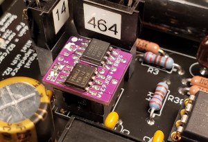
 Adapter board next to standard op-amp. Note that the dimensions are 12.8mm x 12mm. Installed in a phono preamp.

 Schematic
Note: Pins 1, 5 and 8 serve different functions on different op-amps, usually used for offset nulling or bandwidth compensation. The adapter board simply connects these pins through. If these pins are used in your application, you must determine if they will work properly with the op-amp you have chosen.
Two methods of controlling bandwidth are provided on the board.
I have no control over how this product is used, and due to the infinite variety of op-amps and devices they my be installed in… I’m sorry, this product comes with no tech support. I cannot answer questions about the suitability of any particular op-amp to any particular device. This product may cause oscillation, instability, DC offsets, or other issues when used with certain op-amps, or certain circuits. Many factors contribute to a circuit’s stability, such as bandwidth of the op-amp, power supply layout, bypassing, and frequency compensation. It’s up to you to determine if your application is working properly.
See this helpful thread at DIYAUDIO.COM about testing op-amp circuits for stability.
Yes, really! This is a semi-promotional item. Buying from me supports me and my site, or you can download the files and have them made for you. Here are the design files so you can order direct from a board house like JLCPCB or PCBWay. (No affiliation)
Eagles and Parts Libraries:
Gerbers:
You’ll also need the PCB pin headers. They are Preci-Dip part number 350-10-104-00-106101
Won’t people just copy the design, and maybe even sell it? Yes, they will. Please give me credit if you do. Some people will buy from me to support my business. It’s all good.
This is very tricky SMD soldering! Five boards are included in case you screw one up.
Here’s how I do it, using a regular soldering iron. You may have your own favorite method that works. Hot air and solder paste will also work well, but be aware that there are some vias-in-pads that will absorb solder, so these vias should be pre-filled with solder.
(Op-Amp and BUF634A IC not included.)
Buy them here, or download the Gerbers and Eagle CAD files and have them made for you!

Useful wherever increased current drive and immunity to capacitive load is desired. (Headphone amplifiers, line drivers, active filters, equalizers, etc.)
The TI BUF634A adds a fast and powerful output stage to any op-amp. It is inserted into the feedback loop, essentially becoming a part of the op-amp itself.

BUF634A chips are available with or without a heat-sinking “power pad”, and the board is compatible with either. Vias through the PCB footprint conduct heat throughout the board.

I do not sell the ICs. Click here to search OctoPart.com for stock on these items.
BUF634AIDR (SO08 – No Power Pad)
BUF634AIDDAR (SO08 With Power Pad)
It’s also worth checking TI.COM for inventory; they are actually cheaper than most suppliers!
 Adapter board next to standard op-amp. Note that the dimensions are 12.8mm x 12mm. Installed in a phono preamp.
 Schematic
Note: Pins 1, 5 and 8 serve different functions on different op-amps, usually used for offset nulling or bandwidth compensation. The adapter board simply connects these pins through. If these pins are used in your application, you must determine if they will work properly with the op-amp you have chosen.
Bandwidth:
Two methods of controlling bandwidth are provided on the board.
- The BUF634A’s bandwidth is adjustable from 35MHz to 210MHz, set by an SMD 0805 resistor tied between Pin 1 and Vcc. See datasheet for a graph of bandwidth versus resistance. Note that power consumption and heat dissipation rises with higher bandwidth.
- Pads for an SMD 1210 compensation capacitor are provided. The capacitor is connected from the op-amp’s output to the negative input. (From the op-amp’s output, not the BUF634A.) This gives increased negative feedback at high frequencies and limits the bandwidth of the op-amp. This is often done when replacing a slower op-amp with a faster one, to prevent oscillation or ringing. Recommended capacitors; Cornell Dubilier MC series Silver-Mica in SMD 1210 or 0805.
Compatibility and no-tech-support disclaimer:
I have no control over how this product is used, and due to the infinite variety of op-amps and devices they my be installed in… I’m sorry, this product comes with no tech support. I cannot answer questions about the suitability of any particular op-amp to any particular device. This product may cause oscillation, instability, DC offsets, or other issues when used with certain op-amps, or certain circuits. Many factors contribute to a circuit’s stability, such as bandwidth of the op-amp, power supply layout, bypassing, and frequency compensation. It’s up to you to determine if your application is working properly.
See this helpful thread at DIYAUDIO.COM about testing op-amp circuits for stability.
Get boards for almost free:
Yes, really! This is a semi-promotional item. Buying from me supports me and my site, or you can download the files and have them made for you. Here are the design files so you can order direct from a board house like JLCPCB or PCBWay. (No affiliation)
Eagles and Parts Libraries:
Gerbers:
You’ll also need the PCB pin headers. They are Preci-Dip part number 350-10-104-00-106101
Won’t people just copy the design, and maybe even sell it? Yes, they will. Please give me credit if you do. Some people will buy from me to support my business. It’s all good.
Assembly:
This is very tricky SMD soldering! Five boards are included in case you screw one up.
Here’s how I do it, using a regular soldering iron. You may have your own favorite method that works. Hot air and solder paste will also work well, but be aware that there are some vias-in-pads that will absorb solder, so these vias should be pre-filled with solder.
- Start by applying some flux to the all exposed pads on the board.

- First, we’ll install the BUF634A IC. Add a blob of solder to one of the pads.

- Align the chip and melt it down onto the pad

- Solder the rest of the pins.
Note: Some of the solder pads have vias through them, and they absorb solder, so make sure you use enough solder to fill the vias, and still have a nice solder fillet around the IC pins. - Soldering the thermal power pad: (if applicable) Flip the board over, and flow solder into the six vias drilled through the power-pad, until the solder soaks in and wets to the back of the BUF634A. Use enough solder to cause a slight mound to form.

- Install the op-amp using the same method

- Install the bandwidth resistor. See datasheet for values. For maximum bandwidth, simply form a solder bridge across the pads. For minimum bandwidth, leave it open.

- Install the compensation capacitor. (If applicable)

- Installing the pin headers: A 4-pin DIP socket was included in your order, to use as a jig to align the pins while you solder them. Insert the pin headers into the 4-pin DIP socket as shown.

- Add a blob of solder to one of the pads for the pin-headers.

- Add flux to all the pads for the pin-headers

- Align the pin-headers precisely, and melt one to the pad. Solder all the pin-headers you can reach. There will be a few you can’t reach with the 4-pin socket still attached.

- Remove the 4-pin socket and solder the rest of the pin-headers

- Almost done! But that flux is a mess, and some flux is slightly conductive. Drop it in the ultra-sonic cleaner. (I use denatured alcohol in the ultrasonic cleaner and a water-soluble flux, both in the syringe and the solder wire.)

- Done! You might want to check for shorts between pins on the ICs. You might also want to test your new opamp/buffer combo, in a simple circuit on a proto-breadboard before installing it into your precious equipment.
- Start by applying some flux to the all exposed pads on the board.


