Denon DCD-1460 problem with KSS150/210 laser.

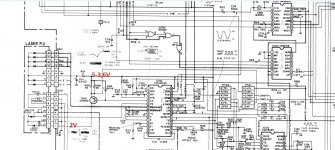
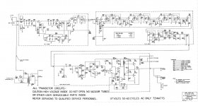
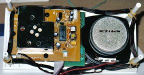
I have problem with Kss150-210 laser in Denon dcd1460. After inserting disk, lens go up an down, disk not rotate, just move a few degrees and no disc. I changed laser optic (removed safety blob) to another and problem is the same. Test run gives result Error 2 ...no FGS (focus gain signal) detected, Measuring current on driver transistor shows voltage drop of around 1,4v on 22r ,so around 65ma current sucks the laser. Voltage on Laserled suply jump to 2v after play. No eye pattern is vissible on test pins. I cleaned laser start position switch.
I am confused that new laser is damaged because it shows same symptoms. Any help where to continue'
Thank you.

Attachments

  • denon.jpg
    denon.jpg
    195.7 KB · Views: 239

CORZUS MD3000 (FALL error )

Hello everyone ! I have this corzus md3000 amplifier that writes FALL on the display. I checked all the mosfets of both the pwm and the power amp and they are ok, the amplifier uses some irs2092 that I replaced and I also replaced some optocouplers! Do you have the schematic for this amp? I searched the internet but couldn't find anything! Thanks and good job

Attachments

  • 20220519_142745.jpg
    20220519_142745.jpg
    314.7 KB · Views: 267
  • 20220519_142740.jpg
    20220519_142740.jpg
    637.5 KB · Views: 294

Reduce Amplifier Gain - Existing Circuit

I have this Fisher amplifier I'm slowly getting in shape for actual use. It's one of those "console" amps that's a separate chassis, but when you remove the rest of it (tuner, preamp) the remaining circuitry within the amp chassis is all screwed up. One problem - after getting the voltages close to the schematic values - is the gain is way higher than I'd like.

Referring to the schematic, the 1st 12AX7 stage has a 470K plate resistor, the highest value I've ever seen (besides a 1M once). I'm thinking of reducing it, but, I'm also thinking doing that would change the feedback gain as well. Given the way that's all coupled to the phase splitter, I'm wary to touch it.

I could simply attenuate at the input by adding a level control - means drilling the as yet "unmollested" chassis for it. Or a resistor after the 47K from grid to ground. That would swamp whatever the 3pf cap does, perhaps changing whatever character the amp once had... Perhaps I shouldnt worry about it.

Any ideas? Thanks!

Fisher_Part.png

starting a new website

Hello to all,

I have started a new website/business that is based on the focus of making things affordable for the common man. This is aimed at making boxes for way cheaper than normal, beauty plates, amp racks, custom fiber glass door panels etc. I also make aeroports for way cheaper than bigassports.com and are the same exact thing. My goal is to drop the price of what it cost to have a car show class stereo system. Check out enuffengineering.com at the moment i havent fully gotten everything up but we are a company based in Springfield, IL. Feel free to contact me with any questions or needs.

This is a no bs website with money back guarantee. if you are not happy send it back ill refund you with no problem.

some pics are not all the way finished projects, some are mobile sound, one is a center stage box i did for a club, others are car audio. pics are just meant to show examples not show fully finished projects.

Attachments

  • image6.jpeg
    image6.jpeg
    890.2 KB · Views: 107
  • image5.jpeg
    image5.jpeg
    375.2 KB · Views: 98
  • image4.jpeg
    image4.jpeg
    626.4 KB · Views: 91
  • image3.jpeg
    image3.jpeg
    682.3 KB · Views: 93
  • image2.jpeg
    image2.jpeg
    457.9 KB · Views: 90
  • image1.jpeg
    image1.jpeg
    1.1 MB · Views: 103
  • image0.jpeg
    image0.jpeg
    698.6 KB · Views: 98

Class D Vs Class I (Balanced Current Amplifier)

Was wondering if any electronics engineers could offer some technical opinions
on the subject.

Which topology is better, class-d, class-i or even class-h ?

From my limited experience in audio, I've learned that most arguments come
down to application, but since they're all a form of digital, perhaps there is
a "better" choice. When I say better, I'm thinking manufacturing costs,
reliability, sound quality and THD etc. Perhaps Class-I is just marketing hype?

I've been toying with the idea of contracting out some designs, hence the question. Application would be _big_ sound...pubs, clubs, events
and competition car audio. The dream is something along the lines of crown's
i-tech and JBL's 6KW beast http://www.caraudiomag.com/specialfeatures/0205cae_jbl_6000_watt_crown/photo_03.html ....probably not quite so big, but along competition lines.

6SQ7 - EL34 SE amp design

This is an SE amp I designed to use the very linear 6SQ7 high gain tube as a driver, built with some Edcor 15W 3.5k OT, to a UL tapped EL34. This amp sounds fantastic and is a simple/cheap design to build. It drives to full power without a pre-amp, which works great with my EAR 834 clone phono stage or straight from a CD deck.

I've tried a variety of 6CA7, KT77 etc. and settled on a pair of JJ EL34 tubes. I played around with various cathode bias schemes (I had no interest in a grid leak bias design I saw some circuits use with this tube), and the combo of a LED + resistor, and tying the diodes to the cathode, sounded the best. Like my other amps, it uses plate to plate Schade feedback and any UL tapped OT from 3.5K to 5K should work fine.

In the future I plan to do another video series on building this amp, but given I found very few designs online for the 6SQ7 tube used for hifi, I thought I'd go ahead and share this.

Attachments

  • 6SQ7-EL34-Single-Ended-Tube-Amp-Stephe-Final.png
    6SQ7-EL34-Single-Ended-Tube-Amp-Stephe-Final.png
    228.4 KB · Views: 3,152
  • 6SQ7-final.jpg
    6SQ7-final.jpg
    61.5 KB · Views: 2,611

Converting Pass Aleph preamp to unbalanced operation

I apologize upfront for what may be a dumb question.

I have a PCB for a Pass Aleph 1.7 preamp. It is balanced input to balanced output. I don't run balanced gear. I know I can use it as designed to accept single ended input and output single ended, but am wondering if I can convert it to just single ended operation.

Attached is the schematic. Would it be as simple as just populating the left side of the schematic and using "+IN" and Gnd for the input and "-Out" and Gnd as the output? I realize this would invert the signal.

Thanks for your thoughts.

Attachments

For Sale An Army of Iron...

I have an Army of Iron for sale: 4 counts of Hammond 193R chokes, 4 counts of Hammond 193U chokes, 4 Antek AS-2T230, 2 counts of Hammond 193A, 200H plate chokes, and 2 Silk grid chokes... all in the amp pictured, not to mention separate power supplies for each tube and the collection of poly chokes within. I am entertaining offers. Of course the entire amp is up for sale if you'd like. Come see me at Chums Corners just outside of Traverse City Michigan. I have several amps and much back stock that I must part with.

Attachments

  • tempImageYg5dL4.gif
    tempImageYg5dL4.gif
    1.6 MB · Views: 373

Gale Gold Monitors Mk1

New to this forum.....hi to you all.
Never really dabbled with hi-fi fault-finding/fixing, just wanted to get that out there 🙂
Recently collected a free set of Gale Gold monitor mk1 bookshelf speakers which came along with an amp I was after. Having read the reviews for these speakers the suggestion is that they are decent budget speakers, let down by wayward treble. Connected them up (bi-wired) to a Cambridge audio a300 amp today and they definitely lack sparkle. At low volume I put an ear to each of the tweeters in turn and swear I could detect very little coming from the left, and nothing from the right. LF drivers seem fine. Disconnected tweeters and both had a resistance of approx 6ohms. Then went to look at resistor and capacitor for each tweeter. I don't have a dedicated meter to measure capacitors, however on the ohm scale the left speaker cap started at approx 10megaohms, then climbed steadily. On the right speaker the cap started at 30megaohms then climbed steadily, although did go open circuit on one measurement attempt.
Duff cap/s perhaps?
Has anyone upgraded the tweeters/resistors/capacitors on Gale Gold Monitors to a successful outcome? If so, which components did you use?
The reviews would appear to bear some truth about HF being wayward but I'm unsure if that's what I'm experiencing, or if I have other issues with the capacitors.
Should I replace the caps, and if so which would you recommend? If you have upgraded to better the treble and bring it better into sonic control, I would be grateful if you could share the detail please.
I'm handy enough with a soldering iron and multi-meter, so, happy to have a go at fixing/upgrading as necessary.
Thanks in advance for any advice you can offer.

For Sale Monolith Magnetics Custom Output Transformers and Chokes

I'm cleaning up and sell all the parts I collected in the past for projects that never left prototype state....

2 custom OPTs Parallel PP 2K2 4-8 Ohm 40% ultra linear taps,C-Core, 140 W, case 3,
very low capacitance with 18 chambers!! THE OPTs ARE SOLD!

4Ω 3.4 Hz - 102 kHz -3dB
8Ω 3.4 Hz - 79 kHz -3dB
Square wave response 10kHz : excellent
Distributed capacitance
Fres grounded 8,8kHz 1760 pF
Fres floating 18kHz 412 pF
induction L = 180 H (quality cores)
leakage induction 4.0 mH

600,00€ the pair(cost far more than twice that much when I bought them, today even more expensive),
since they are very heavy, shipping has to be calculated


2 custom chokes 4H 450mA
, THE CHOKES ARE SOLD!
C-Core, 20Hz sat at full power and >100 kHz bandwidth,
Max AC saturation 640V 100Hz
Saturation without AC flux across the choke will set in at 0.81A
common mode operation on dual bobbin, low stray capacitance,
13 Ohms per winding = 27 Ohms in operation


20220516_194716.jpg
20220516_194736.jpg

20220516_194745.jpg

~30mH inductor for use in pi filter

Hi everyone,

As part of my ongoing project (making a DAC) I have finally got to the output stage. Not only the output stage but the filtering of the output stage!!

Anyway, enough celebrations. I need a ~30mH inductor for use in my filter. I know it seems big, but that is due to its location, which is right at the end of the output stage, right before the final buffer.

Question is:

1) Where can I buy such an inductor?
2) How can I make an high value inductor like that?

I know that Solen make a nice 30mH inductor which is expensive $35US! and very big...because it is aircored. I've also found some sites that contain information allowing the design of aircore inductors. Has anyone here made their own? What is a practical way to do it? How long does it take? Would it be OK to use a metal cored inductor here? Circuit is posted below for information:

Attachments

  • filter final.jpg
    filter final.jpg
    25.9 KB · Views: 391

Tangband Coax W8 2134 pr for sale plus crossovers

One pair of verry good coax drivers for sale with verry good crossovers. They are about a year old but in like new condition. I have original box for this. Price is 400 euro including crossovers pkus shipping inside EU for about 40-50euro.payment thru paypal. More info on PM.

Attachments

  • IMG_20210919_102659.jpg
    IMG_20210919_102659.jpg
    279.7 KB · Views: 937
  • IMG_20210919_102709.jpg
    IMG_20210919_102709.jpg
    299.5 KB · Views: 985
  • IMG_20210919_102725.jpg
    IMG_20210919_102725.jpg
    453.1 KB · Views: 921
  • IMG_20210919_102737.jpg
    IMG_20210919_102737.jpg
    416.1 KB · Views: 978
  • Like
Reactions: SOelker

audio-transformer's impedance: what does "ct" mean?

Good morning allerseits 🙂

I'm on the lookout for audio-transformers (input), found some, but don't know how to interpret it.

The impedances are stated as (@ hammond)

106E = primary: 600 ct / secondary 600
106EE = primary: 600 ct / secondary 600 ct

So this seems to be of a certain significance. Does it mean Center-Tap?

Thank you!
david

Kenwood KAC-821 8026D preamp board...

Hello all. I am new to posting here... I need some help with information on the little ceramic preamp board in the KAC-821 .. turns out when you clean this board with 99% isopropyl alcohol, it removes the resistor and tinned contacts and makes thing go poof... I have the service manual for this amp and I am able to translate where the preamp integrated with the rest of the amplifier. But am up to suggestions on building my own board for a successful repair.

Thanks for your time!
-Kevin

Dual 5v Regated linear power supply - very low current issues

Hi

I just built, what I was thinking to be, a very simple dual 5v linear regulated power supply, to power a rpi-4 and a hat with a digital audio out. I'm running ropieeXL.

The transformer is rated 230v to 2x24v 30VA ( https://www.audiophonics.fr/en/toroidal-transformers/toroidal-transformer-30va-2x24v-p-5649.html ) feeding two LT1084 1.2V / 19.5V 2.5A regulated linear power supply modules ( https://www.audiophonics.fr/en/diy-...th-heat-slug-lt1084-12v-195v-25a-p-11645.html ).

I measured the voltage AC out of the transformer is 24v on both secondery outs, and the output voltage out of the linear power supply module is 5,01v and 5,03v DC on each side. The rpi-4 and the hat lights turn on when I power everything but nothing happen, the rpi-4 lights blink as usual but ropiee never realy starts up, so I checked the current being send to the Board and I get 0.035 amps which may explain why it's not working at all. Voltage still read 5v.

I can't understand why this is happening... is it possible that I wired something wrong ? The boards work because I just connected them to a cheap switch power supply and I can run rupiee and stream music with no issues at all.

I admit I'm totally newbie and probably shouldn't be playing with power supplies, it can really be user error, but I would really appreciate some help 🙂

Thx in advance
Nuno

Folding horn without 3D software HELP!

Hello! So,I want to build a tapped horn for home theater but I dont know how to fold it.Ive seen that many people do it in a 3d modelling software but I dont know how to use any of them.So is there an easier method,like a software or website where I insert the values that hornresp got me and it will calculate and fold me the horn? Also,would this be a good one? The driver is a Dayton Audio DCS305-4. Thanks!
Pillanatkép_2022_05_20_11_25_02_159.png
Pillanatkép_2022_05_20_11_24_54_610.png
Pillanatkép_2022_05_20_11_25_05_761.png
Pillanatkép_2022_05_20_11_25_08_535.png
Pillanatkép_2022_05_20_11_25_26_89.png

Fostex 6301B….

Hi, I have 4 pc’s. Fostex 6301b, which I am very happy with.
Now I want to use them in my 7.2 surround amplifier.
BUT: How do I Connect them to my receiver? There are only loudspeaker output for all the speakers. Front L+R, Center and subwoofer are without Amplifier, so there is no problem. I Can of course modifie the recieve and take the signal “before” it end in the poweramp. But it is a heavy job.
Is there a better solution which is easier.??
Thank you
Rgds

Lars Helsboel
Denmark

Problem with old tube amp

Hi.
Well made tube power amplifer with 4 EL519 output tubes. One channel is playing with less volume. Cant figure out what is problem. Attached oscilloscope photo. Input signal generator with identical voltage. Changed tubes from one channel to another, no change. Input to first tube grille identical. Voltage to output transformer is different. It is about 26 years old. Attached photo from inside also.
Hoping somebody with more experience can give ideas what to check.
Thanks advance!

Attachments

  • EBBDAF0F-6D3D-4AC7-897A-174832F8EE1B.jpeg
    EBBDAF0F-6D3D-4AC7-897A-174832F8EE1B.jpeg
    427.8 KB · Views: 230
  • 62D6B7EC-9CF7-46C5-8B9F-2A65F65AE4B3.jpeg
    62D6B7EC-9CF7-46C5-8B9F-2A65F65AE4B3.jpeg
    658.9 KB · Views: 229

6V6 Regulator Issue

So far everyone has been stumped and I thought this would be a good place to ask. Here's my original post on another forum:

So I finally decided to try out the Raytheon 6V6GT/G and Holland Amperex 12AX7's I have. I was already using the same 12AX7 tubes, I just wanted to test these out. I took all the tubes out and dusted off the preamp chassis and tube tops. I then put all the tubes back in using the new ones. I turned on the preamp and then POP! out of the speakers, this happened maybe two seconds after I fired it up. Startled the crap out of me. I VERY quickly turned the preamp off. I noticed that the Ratheon 6V6GT/G slowly lit up after I turned on the preamp up until the bang/pop where it got brighter much quicker. What's the deal here? The Raytheon tested better than NOS on the sellers tester. I put the RCA 6V6GT back in and all is well, the preamp is fine and all eight tweeters are fine. The Raytheon has an extra pin that the RCA does NOT have.

I took this picture zoomed in too far to be holding the camera, I can't stay still enough for a crisp picture at this much zoom. The RCA is on the right, Raytheon on the left.

LQa6w30l.jpg

Now, the issue is either something happened to the tube during transit or another guess was:

I 100% don't know (sorry), but sometimes tubes have an "extra" pin -- and sometimes it can cause a problem IF a component manufacture happened to use that pin's location on the socket as a "tie point" for other circuit components. It's an admonition one will see sometimes in the tube manuals.

I emailed my tube preamp manufacturer (Dared MC-7P) to see if there would be an issue running a 7 pin 6V6GT/G instead of a 6 pin 6V6GT but they have not gotten back to me so far.

I do have a schematic for my preamp but aside from seeing where the 6V6 is in the power section of the schematic, I have no idea what I'm looking at.

JzfSgcel.jpg


rwlpHqrl.jpg


Any ideas?

Coax Loudspeaker Cable for 2-way Audio Note; why

A set 2-way Audio Note loudspeakers came with a set of double coax cables for each channel. So, a separate coax cable for signal and return.
See attached picture.
Can you please think aloud - or even talk from experience - on why this may be useful?

Please, PLEASE no flame on that cables do not matter.

Attachments

  • LS Coax cable Gubbens.jpg
    LS Coax cable Gubbens.jpg
    899.8 KB · Views: 166

Homebrew Toroidal Output Transformer

I want to share some comments about an experience I´m doing.

I´m doing an EL34 class A UL toroidal output transformer, based on some readings from Menno van der Been, but made of my own. I had done the following try: I buy 3 commercial illumination toroidal transformers, 220V to 12V 25Amper, the biggest I could find. I measured all parameters before unwind, primary resistance, inductance, leakage inductance, etc. So, I unwind two of them, and measured turns, core dimensions, so I could estimate core parameters as, power capacity, inductions, etc.

I done a new winding re-calculating the new cutoff frequency based on induction, cross sectional area, peak voltage between plates, etc. I hand wind equally spread around the core, and in 7 turns one over the others to complete circumference of the transformers, but something was wrong. About 8KHz, the -3dB I could find. The windings are done bifilar about 1000 turns between screens taps, and 1500 more from tabs to plate, a total 40% voltage ratio for screen. I believe that winding in such way, the total capacitance inter-winding is too high. So, I´ll try another form. I want to subdivide the circumference in 10 sectors, separate them by a spacer, and wound single wire in each section. In this way I can have the total 3000 turns in sectors phisically isolated, and capacity must be lower. Two sections will be for the screens (600T) and 3 sections more for the plates (600T +900T = 1500T).

Any suggestions or ideas are welcomed.

Martin Logan Aerius I woofer replacement

Hey guys

I have a pair or ML Aerius I ESLs that I recently had apart for cleaning and capacitor replacement. I hadn't put the lower mesh grills back on yet and last night my cat decided to use one of the woofers as a scratching post.

Would anyone be able to assist me in choosing a set of suitable replacements? To make life a bit easier I'm going to be running the bass section off a Crown pro amp with DSP. I could likely send the stock woofers to Solen and they'd be able to do something for me but I thought the smart people in here might have a few suggestions.

I'll pull the woofer out of the cabinet tonight and grab some pics. It's not completely destroyed but it definitely looks like hell.

Thanks guys

Martin Logan Aerius --no sound from ESL section

Hi. First post. I purchased a pair of martin logan aerius speakers which were sold as having outstanding sound. After paying over 550. for safe,fast shipment. I received a pair of huge boxes for each packaged by ups store and delivered in 2 days . The boxes contained no padding other than 1 layer of bubble wrap but tons of room to bounce around in transit. The seller said that the no sound situation from 1 was probably loose or broken wire. I switched panels, transformers, and then finally the circuit boards where the problem was discovered. One works, one doesn't but both show signs of contact heat blistering under an as of yet identified component which is purpose of my rant and post. Could someone please identify component on circuit board with zip tie around it.and where might it be purchased.. Pic enclosed

Attachments

  • 20160419_003343.jpg
    20160419_003343.jpg
    1,018 KB · Views: 1,126

Digital Clocks and the video chain

I am very interested to understand form an overview perspective, clocks, noise and performance, how the different clocks affect and potentially compromise the performance in the video chain

My set up is Panasonic 9000 4K player (with LPS) this has two (evidently better than average clocks) one main board, one output HDMI, then this goes to a Lumagen 4242 this has three clocks, HDMI input board, main board and HDMI output board, then this goes to a projector (epson LS10,500), which I assume has one or two more clocks

I found improving the power supply in the 9000 with a Coris LPS improved the picture, I have also upon recommendation added three very low noise/jitter clocks to the Lumagen and found quite a signifiant picture upgrade, so wondering where I might still be leaving something on the table.

Any insight appreciated

FS: Troels The Loudspeaker (1 or 2) Drivers + Crossovers

Due to some changes at home, I have absolutely no space for them and that's the why I have to sell the best (and biggest) speakers I have ever had.
To simplify things, I'm selling all the drivers (unless 18" woofers) and all the original populated crossovers (TL1 or TL2 crossovers can be choosen).
All the things to be sold were bought brand new and they have no more than 100 hours of use. In fact maybe less that 70 hours.

I'm sorry but I cannot split anything not share crosover schemas or values. Please, do not ask.

For sale:
2x Fostek FT96H Super Tweeter
2x 18 Sound compression driver NSD1095N 8 Ohm
2x 18 Sound horn XT1086
2x 18 Sound midrange driver 10NMBA520

Crossover for Super tweeter+tweeter section. Original Values
Crosover for midrange section. Original Values
Crossover for Bass section. Original values but no LCR equalisation circuit for 18" woofer (not needed)

Crossovers were built with original values and fits Jantzen audio components:
Z-Superior Caps for Tweeter and super tweeter, cross cap at the begining of midrange and Z-Standard for every other cap in the crossover.
For bass section Elko Superior were choosen.

All the coils are oversized air core coils unless iron cored with discs 1,4mm at woofer low pass.


I'm asking 2300€ for the whole lot.
I can include, a pair of FaitalPro 18F510H 18" woofers that will work like a direct replace for BMS 18N862 woofers for 250€


PP fees if apply and shiping is not included.

Some pictures:


Rockford Fosgate Symmertry EPX2

I will be running my charging system at 15.5 volts for the audio system .

The battery and alternator are totally isolated from the 12 volt system .

Wondering if I can connect the power wire from the symmetry to the 15.5 volt system ?

I connected it the first time to the 15.5 system and smoked the power supply in the symmetry just wondering if it was a fluke

Attachments

  • C03D18AF-817C-4733-936B-E5B53AE5DD0E.png
    C03D18AF-817C-4733-936B-E5B53AE5DD0E.png
    133.9 KB · Views: 101

Feed back resistance value and hiss

I have an amp 200W.@4ohms with a sensitivity of 1V,
with feedback resistor values of 27K and 1K , there by making the gain of 28...which is fine but when I connect the amp to speakers I hear a hiss if I go very near to the speakers , can this be avoided if I use lower value resistors say 10K and 370ohms or 5.6K and 207ohms?
I understand that power dissipation can and will be a issue ? What's the way to eliminate this hiss and this only happens when the amp is connected to my PC.

ELF and Power tubes.

I was using a signal generator to listen to my amp's freq range and determine where the bass seems to roll off. It uses a capacitor coupled output, not a transformer. I am looking to get a few Hz lower rolloff point. I noticed that when down around 5Hz, inaudible, I know, I could see the coronas on the power tubes flicker in time to the cycles, but there was no subsonic movement in the speakers, at the output. Does this mean the rolloff is in the output coupling caps, but that the power tubes are seeing this low frequency? Also, can these ELFs damage the output stage? It seemed that they were making the amp work extra hard, and I think I even noticed a little plate glow, and thought I smelled ozone. Is it possible to produce ozone? I have built a Tesla coil and know well what it smells like. How could a power tube produce this?

Yamaha P2200 VU meter repair

I purchased Yamaha P2200 power amp. I already own P2201 (same app minus the VU meters). The P2200 was missing both needles on VU meters, light bulbs are out but the amp is functional. Measured the output and read 23.5mV and 26.7mV on each channel. Not bad.
I started cleaning the amp. Similar to P2201 I have it is has seen a better days. Some previous owner scratched his name and phone number on the bottom and back plates. Perhaps I should call him once a day...
Once I removed the VU meter plate, I noticed that needles on both VU meters are broken. I removed VU meters and discovered the needles. What would be the best way to glue/secure them?

The VU meter on the left side is working but the one on the right side doesn't. Also the bulbs get no power. I have read that cold solder could be the problem with these amps, something to check...

Any advice on repairing the needles is welcomed. I thought of using superglue with baking soda, epoxy, solder (probably bad idea as the insulation on the needle is likely to get damaged once heated), shrink tubing (won't last and needle could be too close to back plate)... I unerstand the added weight likely to affect meters accuracy.

Wifi audio streamer

I am looking for a very basic audio streaming device. I know there are bluetooth streamers, Raspberry Pi based solutions, etc. What I need is a simple device where I can redirect the audio output of my Android smarphone, and has a pair of analog outputs. Essentially a wifi host + DAC, that I set and forget. Bluetooth quality is not good enough, I don't need any signal processing.

Lithium charging question

Hi,

I lost the lithium charger for a cordless screw driver. The charger cost as much as the screw driver to replace. The charge specs shows 9V 100mA.

When I connect the screwdriver to a power supply and limit current to 100mA at 9V. The power supply shows it is only drawing 1 micro amp.

Any ideas? I should see some current under 100mA if it working?

Any reason why it would not work this way?

Sony TA-N9000ES Repair - Burned Channel

Dear community,
I am in a process of repairing my Sony TA-N9000ES amplifier. I am familiar with electronic, but my skills and experience with power amplifiers are very limited. I hope to receive some advices. A few words on how it failed.
It was a daily use amplifier. Just mid range volume, 8 ohms speakers. I noticed no sound coming out. Checked the amp, it is in protection mode, blinking LED. Turned it off with a power button, after a 20-30 seconds turned it back on and... enjoyed a fireworks with lots of smoke.
After opening it up and brief testing found positive voltage on center channel output. Static component testing showed that most of the components in this channel failed or evaporated, taking out some of the board traces. Did lots of cleaning.... ! First picture shows schematic with failed components in red circles. Second picture shows the worst burned area, in addition to a few more traces just disappeared.
Sony Ta-N9000 scrsht2.png
20220123_171028.jpg

Filament temperature versus anode dissipation

I think that the filament temperature of a valve is strongly dependent on the anode dissipation.
Does anybody know something about this ?
It is possible to determine the filament temperature by measurement of filament voltage and current.
Resistivity of tungsten: 300K 5.65, 1200K 30.98 1300K 34.08 1400K 37.19 1500K 40.36
Can anyone tell me the filament temperature for an 6DJ8, 12AU7, 6V6, EL84, EL 34, 300B and KT88 tube at zero anode dissipation and at maximum anode dissipation.
I think that tube lifetime and SPICE models are strongly dependent of filament temperature.

Grundig NF 1

Hello, I have inherited a Grundig NF 1 that was still functional a few years ago, and I'd like to make some renovation on it. There are has two major issues (beside the usual replacement of caps and resistors) :

1 - the power transformer is made for 220 V main, and my main is rather 240 V.
I have seen in that post https://www.diyaudio.com/community/threads/photo-gallery.71300/post-6843380 the work that Pamook has made on the same amplifier. To lower the voltage from 230 V to 220 V he put a 12 V transformer in series with the main transformer. Can someone explains me the process and what kind of transformer I should use to get from 240 V to 220 V ?

2 - I know that it is recommended to replace the selenium rectifier with a silicium bridge, but some resistors have to be added as the voltage out of the silicium will be higher than the one from the selenium, if I'm not wrong. How may I calculate the needed resistors ?

Thanks a lot in advance.

Beyma 15P80Fe/N Subwoofer

Hi All,
I am looking at the possibility for using Beyma 15P80Fe/N as Subwoofer for Home theater. The idea is to build 2 diy enclosures using this driver.
When I simulated in Winisd, I get the below responses. With the Fs of 32hz, I am simulating a box tuned to 25hz with 400 watts signal (7 cubic feet enclosure)
Please suggest if it is worth building for subwoofer used for movies or should I wait for any better drivers as this is the only model dealer in India has availability.
Is there a better model to get most of it from this subwoofer (like horn loading)?
My original preference was for 18 inch but it is currently not available at the moment.

SPL

1652884481915.png

1652884532625.png


Transfer Fuunction Magnitude

1652884569846.png

Thanks

Tivoli Model ONE vs. KLH Model TWENTY ONE

Attachments

  • KLH Mod TwentyOne21 Radio+Tivoli ONE Front.jpg
    KLH Mod TwentyOne21 Radio+Tivoli ONE Front.jpg
    72.4 KB · Views: 2,661
  • KLH Model 21 inside_after.jpg
    KLH Model 21 inside_after.jpg
    126.5 KB · Views: 2,561
  • KLH Model 21 operating aera open.JPG
    KLH Model 21 operating aera open.JPG
    41.7 KB · Views: 2,487
  • KLH Model TWENTY ONE front.jpg
    KLH Model TWENTY ONE front.jpg
    673.8 KB · Views: 2,747
  • KLH Model TWENTY ONE schema.jpg
    KLH Model TWENTY ONE schema.jpg
    199.8 KB · Views: 4,220
  • KLH Model TWENTY ONE SM.jpg
    KLH Model TWENTY ONE SM.jpg
    4.7 KB · Views: 2,096
  • tivoli model one  hf-rf-speaker.jpg
    tivoli model one hf-rf-speaker.jpg
    82.1 KB · Views: 1,994
  • Tivoli Model ONE Variable capacitor.jpg
    Tivoli Model ONE Variable capacitor.jpg
    75 KB · Views: 1,693
  • Tivoli Model ONE-I inside.pdf
    Tivoli Model ONE-I inside.pdf
    60.3 KB · Views: 1,508
  • Tivoli Model ONE-II inside.pdf
    Tivoli Model ONE-II inside.pdf
    68.3 KB · Views: 1,026

Quad ESL-57 impedance plot and LTSpice model

I found this very informative article on the Quad ESL impedance:

http://www.audiomisc.co.uk/57and303/interact.html

I decided to verify the impedance plot on my speaker, so I used an audio signal generator, a series resistance and an audio voltmeter. I set up the level so that 40mV on the voltmeter corresponded to 10 ohms. Then I entered the measured values in an Excel table and I got this impedance diagram:

ESL_impedance.jpg


I wondered how accurate is the electrical model against the measured values, so I created an LTSpice model. See .asc file attached. I had to modify the electrical circuit by adding a 1.5R resistor series to the 2uF capacitor representing the treble section, so the impedance is about 2R at the treble dip.

1652795450077.png


This is the AC analysis plot:

1652794789143.png


I did not measure the phase. From the analysis it seems mostly inductive below 100Hz, then capacitive up to 20 kHz or so.

Due credits to Sheldon (quadesl.org) for the reference to the ESL Dummy Load originating from Christian Steingruber:

https://www.quadesl.com/origRefs/ampload.jpg

And thanks to Jim Lesurf for the original model that I modified a little and used as the basis of the LTSpice model.

Attachments

  • Like
Reactions: dreamth

School Bass

Hi all

My lil girl needs a decent bass. The kids bass at the music shop feels like a toy and sounds uninspiring to her and she is also struggling with fret buzz. So I thot to eliminate the potential for that and sort something out where she can go ahead and learn all the stuff at school without being burdened by also cleaning up the playing at the same time. The problem is that she is struggling to depress the strings with her tiny fingers

Time for a new project. The perfect kids bass

Materials, a fender style guitar neck and a mini guitar neck. Prepared for filling back the holes and drilling 4 four bass tuners. This project is an experiment building on the time and energies spent developing the TAXI Bass

Necks prepared for filling
Red oak round panel and some leftover birch planks for bodies

ECD366F9-AC27-4525-88B0-68B08A43233F.jpeg
  • Like
Reactions: JMFahey

The most amazing Audio s/w Peace.

The search function is not working so I could not check if this has been posted in the past.
But when it comes to playing audio from a PC I have found nothing can beat this plus its free.

If you know of any GQ which is better than this please share. Also chk out the other audio s/w. They have.
https://sourceforge.net/projects/peace-equalizer-apo-extension/

Looking for pin out for this bose amp

Just finished fixing my akai amp and a bit disappointed with its output.
So I have these bose car amps lying arround. Which i want to use in my workshop.
My question pertains to the pin out.
And if the input to these is from line out of the car deck or the speaker out of the deck. Also if the input to these are difrential or not .
I hooked it up to a kenwood deck line out but got very faint audio.
I have joined both the vcc and ground pins. And powering off a car bat.
20220512_201956.jpg

Hello from Rockford, Michigan!

Came across this site whilst looking for information on how I might go about building a DIY Line-Array speaker system. We host yearly parties on our property, and our friends are all into Bass EDM music. So a couple times a year we have DJs out and throw a big party. The speakers that I have now work very well, and fill our space very well with sound, but I'm not super happy about the quality of the mids and highs. I'm into woodworking, software development, electronics, music! So, outside of the math and physics involved with speaker design, I can do most of the other stuff.

My current setup is:
(2) Rockville PBG18 Subwoofers each with QSC PLX3002 Amp
(2) Rockville 12.4 12" 3-way speakers each with QSC PXL1602 Amp.

The PBG18's work quite well for the low end, but the 12.4's leave a bit to be desired. They sound a little tinny and not very full.

I was looking to build (2) to start, and add more later, some line array style speakers that I could hang from my patio roof and aim down towards the audience (budget of about $3000 for a pair). Just from my initial browsing (I fully admit I don't know much about matching speakers (*yet)), I put this together for each speaker:
(2) Faital 10FH500 in parallel
(2) Faital 6PR110 in parallel
(2) Faital HF107 in parallel

Looking for any and all input regarding types of speakers, cabinet design, tuning ports, crossovers, etc.

Thanks!

Apex PA05 Power Op Amp as an audio amp

Hello All,


Back in the mid ‘90’s I had the opportunity to acquire, at a very modest cost, a few Apex PA05 power operational amplifiers, along with their evaluation kits. The amplifiers are rated for an internal dissipation of 250 watts, and a maximum supply of +/-100V. The evaluation kit contained a very nice heat sink with a thermal resistance of 0.68ºC/W, and a large PCB. I experimented with them as audio amplifiers (see attached pictures and schematics). I had no intention of pushing the power envelope, I was happy with 20-30 watts into 8 ohms, so I used +/-28V regulated power supplies. I used the amplifier for a couple of years as an office system listening mostly to FM. It sounded okay with speakers, but when I tried to use it as a headphone amplifier, the background hiss level was so bad I gave up and put the amp in the cupboard. At the time the only measurement equipment I had was an analog multimeter and an analog oscilloscope.

Recently I had the occasion to put the amp back in service for a few weeks while I worked on my current office system. While I had it out, I thought I would look at the distortion spectrum with the QA401 (see attachment), which looks pretty ugly to me. The data sheet specs the THD at 0.01% at 1KHz at 1W. Anyone care to offer suggestions on how to go about cleaning up all that distortion and noise? By the way, I am aware that the safety ground is incorrectly implemented, and if I can solve the distortion problem and put the device back into service, I will correct this error.

Cheers,
ceulrich

Attachments

  • Low Power Audio Amplifier 1.jpeg
    Low Power Audio Amplifier 1.jpeg
    502 KB · Views: 625
  • Low Power Audio Amplifier 5.jpeg
    Low Power Audio Amplifier 5.jpeg
    286.6 KB · Views: 644
  • Low Power Audio Amp Schematic 4.jpg
    Low Power Audio Amp Schematic 4.jpg
    42 KB · Views: 699
  • PA05 Low Power Amp Power Supply 2.jpg
    PA05 Low Power Amp Power Supply 2.jpg
    59.3 KB · Views: 676
  • PA05 Low Power Amp - Left - Distortion at 1 W : 4 Ohms.jpg
    PA05 Low Power Amp - Left - Distortion at 1 W : 4 Ohms.jpg
    156.1 KB · Views: 593

Building a subwoofer into my wall

This is my current office design:

inwall-render.jpg


Obviously, that corner bit is 'awkward' - perhaps a few cupboards that are hard-ish to reach.. or.....

A subwoofer for the cinema in the next room?
inwall.png


Questions:

1/ Would this be a good idea? Since I'm building this house from scratch I have a lot of freedom when it comes to e.g. the wall thickness, type, bass port etc etc. With the current sketch it'd be about 30 cu feet, padded with felt I guess?
2/ What's a reasonable wall width and material? 1 inch as I indicated here is probably a bit flimsy? Concrete? (no idea how to even create a wall like that.. a mould perhaps?) How about 100mm brick?
3/ What actual driver(s) should I get? What configuration? Depends a lot on how loud I need to go but as an indication the exit port is about 5m from listening and hitting 115dB (thx) at listening for say 10Hz would be ideal?
4/ Any suggestions around the exit port that has to tunnel through the wall? Does it have to be the size of the driver(s) or can I make something more reasonable like 5x5inch or so?
4/

Quad ESL-63 - A simple discussion

OK, count me as one of the many that just love - love these speakers! I have the Quad ESL-63 and the ESL-988...and are my favorites!

And I trust what I am about to say is not to be taken as Quad Blasphemy!

Yeah, all those that say the removal of the dustcover does not change its sound at all.... and I agree. And understand I am not advocating the removal of the Dustcover as it will not improve the SQ....

But, that only can mean one thing - ready?

That because what you are really hearing is the DUSTCOVER, not the actual panels thru the Dustcover. The sound cannot pass thru the mylar Dustcover. The Dustcover is a measly 3um for this reason. Its Supersensitive Acoustic Coupling, not unlike a passive radiator in a box speaker.

So, if some agree that we are hearing the Dustcover only, the delay rings on the panel - how the sound propagation of these delay rings can somehow superimpose onto their exact locations on the Dustcover to do as they are designed to do... huh?

I have always wanted to build an infinite baffle type speaker (w/ tweeter, bass drivers, etc), and put a "box" around the baffle edge to be able to pull a 3um mylar on both sides to see if this speakers separate (front / back) airtight "Dustcovers" Acoustically couples all the low, mid, and high frequencies and and allows all the frequencies to emanate off one (well, two) common surface, just like the Quad or any other Electrostatic speaker...all with basic "box" drivers...

Go ahead, call me crazy.

Dalesford D50/200 replacement

Hi there,
I picked up a nice looking pair of RAM Electronics 100 Monitors the other day for £30 (£15 after refund). I soon discovered that one of the bass units (Dalesford D50/200)was dead. No sign of damage and the cone moved smoothly and quietly. Not sure what its fate was.
Anyway, I need a repalcement and my initial thoughts were to get Kef B200 units. I initially thought SP1014's which are quite easy to get. Then I found a link on Falcon Acoustics who have an interest in that company. The chap there suggested I should be getting the large magnet variety SP1039 or SP1054. Pricier and harder to find it seems. No mention made of the SP1022.
I wouldn't say that the D50/200 is a large magnet type, but the design is clearly B200 related but with inverted rubber diaphram. It weighs 1.67kg. The large magnet Kef's are about 2.7 to 3kg. The regular ones around 1.47kg.
I then wondered if I am better just going for a pair of new Monacor SPM-205/8 units?
Any advice. I want to keep any work low cost or else I will just sell for parts.
I think the one remaining D50/200 may help fund the unit purchase a little as they are quite uncommon.
Cheers

  • Article Article
Ferrite cored autoformer design for headphones (and potentially volume control)

Having just designed a DAC with a single-ended classA output stage which drives high impedance headphones well, I wanted to explore options for expanding downwards the range of HP impedances that could be driven. SE classA has a brickwall limitation on output current and goes into aysmmetrical hard clip at the point where the output current equals the bias current. As a result, it needs to be designed with a specific load impedance in mind so that current clipping isn't the primary constraint - the DAC is optimized for 300ohm (Drop HD6XX). Having played in the past with transformers for HP drive I figured it was worth revisiting this area but this time around going the autoformer (rather than transformer) route.

The disadvantage of an autoformer (aka 'tapped inductor') is that there's no isolation between primary and secondary but in this application that doesn't bother us at all. The upside is better utilization of copper resource, though the degree of this advantage depends on the target turns ratio. The greatest advantage comes in near-unity ratios. i'd like to explore whether a rudimentary volume function could also be included alongside the impedance transformation.

Since I have a box full of PQ3230 core sets I figured I'd make a start with that size. A couple of months back I built a 1dB step AF (autoformer) attenuator to sit between DAC and amp using PQ3230s so it was a matter of seeing how to adapt that for HP use. Adaptation of something already extant being much easier than design from scratch. There are two main concerns when the intent is driving HPs rather than the light load of an amp's input stage. The first is - 'what are the losses in the copper?' and the second is 'what's the bandwidth?'. These two concerns are inter-related as the more turns an AF has the greater its losses and the lower its bandwidth. So one aim is to minimize the number of turns. Pushing up against that though is a third concern - 'what's the shunt inductance?' - the core material being ferrite without a sky-high mu (as permalloy for example has) this does factor. So we don't want to go too low in turns or the trafo will 'steal' too much of the output current for its own energization.

The question of the bandwidth of the AF is something that cannot easily be predicted in advance, it has to be explored empirically. In order to make a first stab at it, I loaded my 1dB step AF with a 30ohm resistor and took a look at the HF roll-off. It showed a -3dB around 5kHz, definitely not sufficient for audio. The low-pass response is a function of the AF's leakage inductance - to get a wider bandwidth we need to get that leakage L down by at the very least a factor of 4 (which would give -3dB @ 20kHz, in the ballpark but not really ideal). Rather than build an AF with half the number of turns (to get a quarter the inductance, and hence leakage inductance which is a fairly stable ratio of that) I decided to run a sim. The sim showed I can tweak the HF roll-off upwards by introducing a cap across the 30ohm, thereby gaining a dB or so in extra HF flatness. So it looks as though I just need to build an AF with half the number of turns of my 1dB step attenuator. Since that was designed to handle about 9VRMS, the HP AF will have 4.5VRMS input voltage handling which is more than enough given the DAC only outputs 2VRMS. I will go for a 4VRMS handling to have a little more bandwidth in reserve as sims don't always closely match reality in trafos.

The PQ3230 core has a cross-sectional area (Amin) of 142mm^2 which gives 161turns/volt at 20Hz. So to handle 5.6V peak at the worst-case frequency I'll need 5.6*161 = 901.6 turns. Let's go for 900. To get the required wire gauge we divide the available winding window (101mm^2) by 900 and take the square root. 0.335mm external diameter wire. Wire's sold by internal (copper) diameter so this says about 0.29mm to allow for insulation. If the wire's enamelled then allow a little more. Knowing the wire diameter needed we can estimate the total length and hence DCR and with the DCR we can check if the copper losses are going to be sensible into various HP impedances. The rule of thumb I've seen is that the driving impedance should be not greater than 1/8th of the HP impedance. So for the lowest impedance HPs this gives about 4ohm source impedance as a ceiling.

From my handy trafo design Excel crib sheet I see that PQ3230 bobbin has an average length of turn of 67mm so with 900T we'll have 60m of wire. 0.29mm wire clocks in at 0.27ohm/m so that's 16.3ohm total DCR end-to-end. Sanity check - the original 1dB step AF measured at 79ohm so we are in the region of 25% as predicted. To get the effective DCR 'seen' by the HPs we need to know the tap ratio - 300ohm down to 30ohm is sqrt(10) in voltage ratio. Whereas calculating effective impedance in transformers is easy, I'm not sure my mental heuristic works in the autoformer case so I'll run some sims as what Daniel Dennett calls 'intuition pumps' and then continue in another post.

200 w rockola amp problem

I have assembled the stereo version of the amplifier in the attachment. My problem is when I give power to the amp, after connecting the speaker, the series bulb is in "ON" state indicating DC voltage in output. If I give power first and then connect speaker there is no DC voltage at output and if I connect an audio input the output can be heard from amp without no audible distortion. Both channels have same problem. Please help me to correct the problem.

Attachments

Build with unusual tubes

A japanese bok ISBN4-416-19209-6 (363 pages, printed 1992, Koichi Shishido) describes the following tube amps:

*DA30 8W single end, interstage transformer
*811A 8W single-end, interstage transformer
*801A 8W single end, interstage transformer
*826 8W single end, interstage transformer
*RCA-808 12W single end, interstage transformer
*RCA-800 10W single end, interstage transformer
*8012A single end, interstage transformer
*826 8W single end
*RCA800 28W PP, interstage transformer
*RCA830B 15W single end, interstage transformer
*UV-838 35W single end, interstage transformer
*805 50W single end
*6N7 7W PP
*6L6 PP
*4D32 20W single end
*preamp with 6DJ8

Tripath TA 2022 BTL mode offset adjustment

In my Poppulse T180 amp one of the TA 2022 IC-s (one per channel, BTL mode) gave up the fight (no heat conducting paste between the the IC, and the heatsink ! ) , so I ordered one and replaced tha failed chip. The problem is, that now I have almost 1V DC on the speaker terminals, and the circuit uses two trimpots to adjust the 0V DC on the output. I have the data sheet of the IC, but it does not tell you how to adjust the DC offset in BTL mode. Any idea?

Attachments

  • poppul11.jpg
    poppul11.jpg
    119 KB · Views: 219

Blast from the past - Kenwood KA-80

Well, I was always wondering about this one since I heard it some 20 years ago.
Then last week by chance found a perfect condition specimen on the local flea market for peanuts, so I decided to give it a chance.
Doing the compulsory homework on a 30 years old amp -replaced all electrolytics in the power stage with Silmic II-s, and Kendeils in the power supply + ultrafast rectifiers- I was totally blown away from what came through on this old piece of hardware....
Having owned, built and listened around 100 different amps (some really good ones too) in the last 30 years, let me tell you, this is a very different animal as far as speed and transparency concerned.
Maybe I am just getting old and losing my marbles, but let me tell you, these guys at Kenwood knew something by then that very few manufacturers are able to repeat today.
The sheer clarity, transparence, and attack of this little amp is breathtaking.
I am hearing information in the upper octaves that sometimes just plain scare me, because they come through with such a realistic way, I often confuse them with environmental noises. Never experienced that with ANY other amp before.
On the attached pictures you can see, that they did their homework on output stage design.... Split feedback for the VAS and current amp stage, critically applied phase correction and speed-up components at all place.
Even that old Darlington power pack does its job in an excellent way, this thing reproduces 40 kHz square waves perfectly, without overshot and ringing.
After all, I am curious about some expert opinions from you, any comments advices, criticism concerning the design?

Attachments

  • kenwood_ka-80_sm-006.jpg
    kenwood_ka-80_sm-006.jpg
    239.4 KB · Views: 1,091
  • kenwood_ka-80_sm-007.jpg
    kenwood_ka-80_sm-007.jpg
    288.6 KB · Views: 1,293
  • kenwood_ka-80_sm-014.jpg
    kenwood_ka-80_sm-014.jpg
    510.7 KB · Views: 1,007

JLH 2005

Hi all.
I build jlh 2005 using Paulb circuit and pcb. Now i face issue sound is too low. Use +-30v supply range. And use 2sc5200 for power output. 2 pcs 2sc5200 already died cause over bias(sad)
I double check hfe value for bc560, bd139 and bd 140 all in good range.

I don't have oscilloscopes and signal generator to measure input output gain.

CamillaDSP-Monitor, a RME ADI-2 DAC like DSP flow

I spent a weekend writing a small and simple software program that performs most of the DSP features in the RME ADI-2 DAC/Pro, mainly for using it personally on a laptop when travelling without the device.

The program applies DSP system wide based on CamillaDSP, and has identical output compared to the RME ADI-2 DAC/Pro, with various features including volume adjustments, software muting, RMS and PEAK volume calculations before and after DSP, Width, M/S Proc, Phase calculation, 5 levels of crossfeed, EQ for headphones or room corrections, Loudness, De- or Pre-Emphasis, and DC Protection. It also has Digicheck's 30 bands spectral analyzer for left and right channels, and can give identical results as the ADI-2 does.

The implementation follows ADI-2's pipeline as much as possible, sometimes exceeding the hardware limitation of the original device. For instance, user can have as many EQ bands as possible. On the other hand, it has longer latency and higher CPU usage, as the processing is not done in hardware.

I believe the software program could be useful for many people so I decide to make it open source.

Here's the github link: https://github.com/Wang-Yue/CamillaDSP-Monitor

Please play around with these features, discover the usefulness, and have fun!

Bear in mind this is alpha quality software. It works well in my setup, but whether or not it will burn down your house is unknown, and I hold no responsibility for that. With that said, all the bugs or glitches are due to my sloppiness, not CamillaDSP or RME.
  • Like
Reactions: chris719
Projects by fanatics, for fanatics
Get answers and advice for everyone wanting to learn the art of audio.
Join the Community
507,639
Members
7,882,073
Messages

Filter

Forum Statistics

Threads
405,939
Messages
7,882,073
Members
507,639
Latest member
xwiggen