Hi Guys,
I recently acquired a very nice little amp from a Gulbransen G-3 organ (circa 1960) for the staggering price of free. Unlike most tube amped organs, the Gulbransen company always used transistor tone generators, but their amplifiers were all tube. Each amp was a stand alone unit that could literally be unplugged from the organ, unbolted and pulled right out.
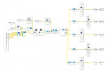
So that's what I did:

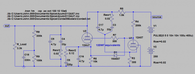
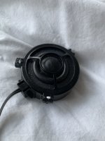
This makes them ideal for guitar amp conversions. That, and the fact that the amp uses a pair of 12AU7's, a pair of EL84's, EZ81 rectifier, and the typical heavy iron found in organ amplifiers. The G-3 also sported a pretty nice rotating Leslie unit with a very nice looking 12" Alni/Co speaker driver.
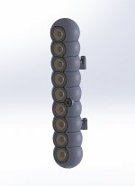
Initially, I was planning to part the whole thing out, but then the mental gears started turning, and I saw how simple it might be to simply cut away everything that wasn't part of the Leslie cabinet, mount the amp on top, and I'd have a sweet little rig.
The rules were simple. I would use only cabinet and electrical parts from old organs, except for the three-prong cord and whatever replacement capacitors and resistors I might need to replace or add. All Potentiometers, wiring, screws, switches, and hardware are from organ pulls.
Now, I'm in the fine tuning and tweaking stage. The thing sounds fairly amazing. The cabinet is enormously heavy and semi-sealed, with the driver facing downward. It sounds like what might happen if you built a guitar amp into the body of a cello. Very warm and woody. So much resonance it sounds like there's a spring reverb.
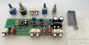
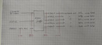
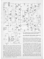
I've posted a copy of the amp schematic below.
What I've done already:
- Removed the 500k volume pot from between the input and V1.
- Clipped out the death .5 mfd cap at the Power Transformer.
- Cut out the Non Feed Back loop 22k resistor from the output transformer/speaker.
The Leslie sounds are amazing. It's incredibly 3-dimensionsal. You can tell what they was trying for with the Univibe and subsequent phasers, but this thing is like actual sex compared to just looking at pictures. There's just nothing like a real Leslie. It's like swimming in sound.
Here are my plans and needs:1. I want to use a 12ax7 in the V1, and V2 positions instead of the wimply 12AU7's. I've tried one in the V1 already and it gives me way more gain (obviously) and sounds pretty good. But I'm worried it's too much gain for the circuit. How should I modify it to acheive this safely? Also -There's not much sonic difference with a 12AX7 in V2. Why?
2. I need a decent tone stack. The one that's there now is operated by the "expression pedal" and is designed to optimize organ sounds. I can hear it sucking tone. I'm thinking of just using the ladder style stack from a Fender Princeton Reverb with Bass, Treble, and Volume. But I'm not sure about the resistor values. Can I just pop in the same values as are in the black face PR's? Is there a better tone stack idea? I don't want to do midrange or active or anything crazy. But I'm considering a VOX stack with the grounded bass pot as the tube lineups are similar.
3. I'm keeping the selenium rectifiers and all the weird stuff at the bottom of the sheet because that's what the amp uses to switch the Leslie motor on and off. There's a relay.
I've clipped out the 17 DCV brake on the Leslie motor, however, because I want it to spin down slowly. In fact, I have a two speed motor that I grabbed from another organ that I'm going to try to switch in for the one speed I have now. I don't know much about motors and AC current. Is there a way to simply give my motor 50 VAC instead of the 117 VAC it is getting now?

Just prior to leg amputation:

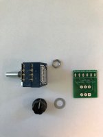
Beer is good food. The volume/expression pedal is operational. It has the most incredible potentiometer design. I'll take a picture next time I have it open. It's not a pot really, just a series of about 12 resistors:


The cabinet is flipped on it's side here for construction:

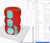
The Leslie footswitch. Amazing 50's technology. The leathery looking stuff is from the back cover of the Gulbransen. It is just a hardboard/pressboard stuff but it has an embossed face, and looks like real leather. The vents were for the amp. I liked the look so I'm cladding all of the exposed poplar faces with it:

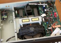
The chassis is copper plated steel. Yes. It is gorgeous.
Tidy, but tight. I expect to cut some more junk out, but I'll be adding a couple of tone pots:

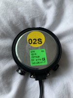
Nice sounding speaker by an unknown manufacturer. That EIA code is a mystery:

I will continue posting pics as the project progresses, and some sound clips/video as well.