Hi guys, nice to meet you. I'm new to this forum and to diy audio. Bored at home, and missed to use the soldering gun so i decided to order an diy tone control kit on ebay and try to learn something in the spare time, so here i am...
My actual target for the moment is just to add an external tone control to my integrated stereo amp, maybe with 2 nice vumeters in a fancy homemade cabinet.
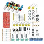
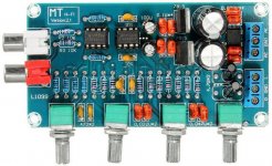
The kit that i ordered uses the ne5532 opamp.
I have few questions, how can i change the hz values of treble and bass replacing the components? Does that scheme allow to bypass the pre amp section and use only the opamps for tone controls(or maybe i'm too confused)?
DIY Kits NE5532 Preamp Pre-amplifier Tone Board Treble Alto Bass Volume Control | eBay
My actual target for the moment is just to add an external tone control to my integrated stereo amp, maybe with 2 nice vumeters in a fancy homemade cabinet.
The kit that i ordered uses the ne5532 opamp.
I have few questions, how can i change the hz values of treble and bass replacing the components? Does that scheme allow to bypass the pre amp section and use only the opamps for tone controls(or maybe i'm too confused)?
DIY Kits NE5532 Preamp Pre-amplifier Tone Board Treble Alto Bass Volume Control | eBay
Attachments
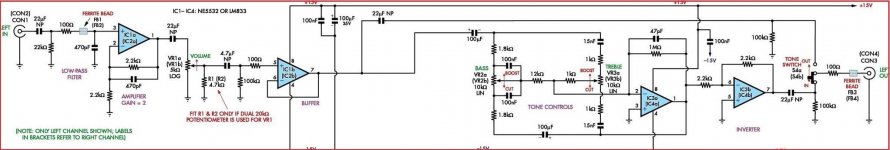
You'll need to get a schematic diagram (or trace out the circuit) to make any changes in the capacitor values.
This seems to be a stereo 20dB gain line stage combined with an active tone control stage.
It includes the power supply, except for the 12V to 17V rated AC power transformer.
Seems to be sold at a very reasonable price.
This seems to be a stereo 20dB gain line stage combined with an active tone control stage.
It includes the power supply, except for the 12V to 17V rated AC power transformer.
Seems to be sold at a very reasonable price.
Last edited:
Its probably a Baxandall tone circuit, and as with all RC filters you can scale the C's or the R's to affect the frequencies. Higher values for lower frequencies in either case, but keep all the C's in the same proportion and all the R's in the same proportion. However some R's won't be in the filter circuit itself and shouldn't be scaled.

The “NE5532P” that is sold with that kit is definitely a counterfeit. The DIP-8 epoxy mold and marking doesn’t resemble authentic TI NE5532 that I bought off authorized distributors (Mouser and DigiKey).
Google “Audio Radio Handbook” by National Semiconductor. It has a lot of information about audio design that people should be reading. It has the answer to your question on tone controls. I grew up reading each of the pages over 35 years ago. I still have the book. It’s the 2nd book I bought after Electronics Made Simple by Henry Jacobwitz when I was in 5th grade. Then it was free printed National and Motorola databooks and application manual after college.
I’m a visible minority and originally from the Far East so you can imagine the scarcity of technical books that was available to me. My high school has one textbook in electronics in their library and the author was Russian! It mentioned servo which was Greek to me back then.
The internet is a great tool that people take for granted. Use it wisely.
Last edited:
It looks like a nice kit, good to learn from, even if the op-amps are counterfeit. You can get a better one if you don't like it, or just plug in real NE5532s, which will cost much more to ship than they're worth from a reliable supplier.
I am working on a preamp you could build if you decide you want something better...
GitHub - profdc9/PrettyGoodPreamplifier: A Pretty Good Preamplifier for Stereo and Subwoofer Use
I am working on a preamp you could build if you decide you want something better...
GitHub - profdc9/PrettyGoodPreamplifier: A Pretty Good Preamplifier for Stereo and Subwoofer Use
I bought two different versions of these and had a thread on reducing the gain down from 20dB.
Ebay NE5532 pre amp tone control gain reduction
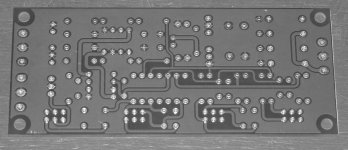
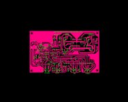
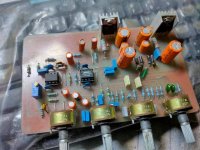
With mine I threw out the components and used my own. For info I've added some pics of the PCB if anyone wants to trace it for the OP. If you want to by-pass the tone circuit you have to do it prior to the input on the PCB.
Ebay NE5532 pre amp tone control gain reduction
With mine I threw out the components and used my own. For info I've added some pics of the PCB if anyone wants to trace it for the OP. If you want to by-pass the tone circuit you have to do it prior to the input on the PCB.
Attachments
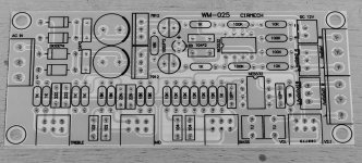
This is the board I bought on ebay. I traced the schematic myself.
At Download there is a program for tone controls as used in guitar amps. May be of interest... or not.
At Download there is a program for tone controls as used in guitar amps. May be of interest... or not.
Attachments
+1!!!!

1meg in tone control feedback seems very high....
Totally bypassed by 10k tone networks. 1Meg is just the DC limit. Yes, you can have oscillation, especially with remote mount tome pots, but that's layout not impedance level.
I posted on another thread. This is the schematic Im using. Its an old design.1meg in tone control feedback seems very high.
I get oscillation with 100k in feedback loop in some situations.
With 47pf and 1meg this gives -3db point as 3300 Hz.
I would be looking at more like 100k and 150pf in feedback loop
The problem Im having is a lot of distortion on the output I have spent the last 3 days looking for videos that show what an output from such a board should look like on a scope. All I see is a lot of Noise.
Things I have changed.
1. Moved to all MFR resistors 1%
2. Replaced all the NE Ics with TI Brand NE
3. Put a 100Nf ceramic disc cap across Pins 4 and 8 for all the ICs.
My mentor says the output should look the same as the input signal except higher voltage. But all I see is a Thicker sine wave output.
A couple things jump out at me whilst viewing that circuit:
- Those electrolytic coupling caps should all be Nichicon MUSE BiPolar caps
- The power supply could benefit GREATLY from Elvee's 3-pin regulator modifications. This will reduce the PS noise and impedance a LOT.
Which is it??All I see is a lot of Noise.
But all I see is a Thicker sine wave output.
What kind of "noise"? Hiss? Hum? Motorboat?
A "thicker trace" may be a small amount of any of the above.
The circuit laying out in the open WILL pick up all the interference in the room. That's why we have metal boxes.
Why dos that have TWO volume controls? RV5 and RV3 RV4. The specific advantage of the Baxandall volume control RV3 RV4 is that it gets a near-log response from a low-price well-matched linear pot. Here less-matched audio-taper(?) RV5 is messing with the balance and RV3 RV4 is a costly trim.This is the schematic Im using.
However with RV5 at max and RV3 RV4 and tone-knobs centered it should be unity gain over the audio band. Fed a 100Hz signal and turn BASS, the 100Hz should be bigger/smaller.
- Home
- Source & Line
- Analog Line Level
- tone control using ne5532