Hello, this is my first post here.
Last year I’ve purchased a pair of Meyer Sound HD1 in partially working condition.
One LF driver wasn’t working and the amplifier of the other unit was producing some noise time to time, because of a bad joint on one of the rectifiers.
I’ve fixed all the faults, the LF driver had both the flexi wires broken in the point where they are attached to the faston terminals.
All the seals of the trimmers (about 45 per unit, if I recall correctly) are intact and the manufacture year of the pair is 2000.
They are quiet when no signal is input, just some slight hiss from the HF driver, which can’t be heard at 1 meter of distance in my room.
I know how (good) they should sound, since a friend of mine has a freshly calibrated pair. My pair has a strange behavior: frequencies from about 1 kHz to 4 kHz are too much present, up to become annoying with some female voices, strings and brass. Acting on a parametric eq isn’t of too much help… the sound is still harsh and fatiguing, when high energy (acoustic level) is concentrated in the critical band 1 to 4 k, and dull at lower levels. There is some non linear behavior with level changes in the range of frequencies specified above.
The higher the level, the higher the nuisance.
One thing I’ve noticed is that, when touching the dome of the tweeter with a nail, it produces a sound similar to a phenolic diaphragm used in compression drivers. Also the consistence is rather hard, similar to a phenolic diaphragm.
I’d like to know if this is normal is the consistence should be like all the treated silk domes.
I believe that the issue is due to some distortion, perhaps originated by a shifting of the FS (if the dome hardened or if the ferrofluid dried, assuming that the unit originally employed ferrofluid in its gap).
The issue is the same in both speakers and I believe the electronics are ok.
Is there anyone who experienced a similar problem?
Thanks,
Giorgio
Giorgio,
While I have no personal experience with the Meyer Sound HD1, have had experience with changing response due to aging ferrofluid and/or junk in the magnetic gap. Also, like speaker surrounds, a "soft" dome may harden over time.
Frequency sweeps can make it easier to isolate problems and test frequency response, the HD1 should have very flat response.
REW is a nice freeware application for testing :
https://www.roomeqwizard.com/
The HD1 has an interesting feature:
"Two‑channel complementary MOSFET output stages and operates at class A at low to moderate levels (less than 90 dB SPL) and class AB at high levels."
If that transition was not working properly, could be responsible for what you are hearing, which may be what is known as "Crossover Distortion", a zero voltage “flat spot” or “deadband” on the output wave shape as it crosses over from one half of the waveform to the other. Those flat spots definitely would sound harsh, adding nasty harmonics.

REW also has an oscilloscope function, if you were to test the HF amplifier output you could see if a sine wave looks clean or distorted through the level change range where you hear the non linear behavior occur.
Good luck tracking down the problems!
Art
While I have no personal experience with the Meyer Sound HD1, have had experience with changing response due to aging ferrofluid and/or junk in the magnetic gap. Also, like speaker surrounds, a "soft" dome may harden over time.
Frequency sweeps can make it easier to isolate problems and test frequency response, the HD1 should have very flat response.
REW is a nice freeware application for testing :
https://www.roomeqwizard.com/
The HD1 has an interesting feature:
"Two‑channel complementary MOSFET output stages and operates at class A at low to moderate levels (less than 90 dB SPL) and class AB at high levels."
If that transition was not working properly, could be responsible for what you are hearing, which may be what is known as "Crossover Distortion", a zero voltage “flat spot” or “deadband” on the output wave shape as it crosses over from one half of the waveform to the other. Those flat spots definitely would sound harsh, adding nasty harmonics.
REW also has an oscilloscope function, if you were to test the HF amplifier output you could see if a sine wave looks clean or distorted through the level change range where you hear the non linear behavior occur.
Good luck tracking down the problems!
Art

Dear Art, thanks for your tips. Fortunately I have several audio analyzer and, for me, it’s easy to determine if an electrical circuit has anomalies. I will check the amplifiers.Giorgio,
While I have no personal experience with the Meyer Sound HD1, have had experience with changing response due to aging ferrofluid and/or junk in the magnetic gap. Also, like speaker surrounds, a "soft" dome may harden over time.
Frequency sweeps can make it easier to isolate problems and test frequency response, the HD1 should have very flat response.
REW is a nice freeware application for testing :
https://www.roomeqwizard.com/
The HD1 has an interesting feature:
"Two‑channel complementary MOSFET output stages and operates at class A at low to moderate levels (less than 90 dB SPL) and class AB at high levels."
If that transition was not working properly, could be responsible for what you are hearing, which may be what is known as "Crossover Distortion", a zero voltage “flat spot” or “deadband” on the output wave shape as it crosses over from one half of the waveform to the other. Those flat spots definitely would sound harsh, adding nasty harmonics.
View attachment 1072169
REW also has an oscilloscope function, if you were to test the HF amplifier output you could see if a sine wave looks clean or distorted through the level change range where you hear the non linear behavior occur.
Good luck tracking down the problems!
Art
I will try to trace a FR using REW, but first have to download it and learn how to use.
The loudspeakers used in the HD1 are custom parts manufactured here in Italy by CIARE. Unfortunately there isn’t any specification available for the parts used.
A day I will remove and open the HF driver to inspect the gap. Perhaps they didn’t even used any ferrofluid, who knows.
So the issue may be due to some hardening surrounds or drifted electronics.
Giorgio
Giorgio,So the issue may be due to some hardening surrounds or drifted electronics.
From your description, the tweeter dome as well as the surround hardened. The tweeter damping material behind the diaphragm may have degraded too, foam types may crumble or turn to mush as they are affected by other hydrocarbon out-gassing (evaporation).
Some of the trimmers may be analog filters used to match frequency response to account for the usual manufacture tolerance errors, which can be +/-3dB (or more).
If they are, you may be able to replace the tweeter diaphragms with something similar to the original, and re-tune for flat response.
Art
Art, I believe that the internal EQ section has something like seven band parametric control, while the delay card is about the same complexity.Giorgio,
From your description, the tweeter dome as well as the surround hardened. The tweeter damping material behind the diaphragm may have degraded too, foam types may crumble or turn to mush as they are affected by other hydrocarbon out-gassing (evaporation).
Some of the trimmers may be analog filters used to match frequency response to account for the usual manufacture tolerance errors, which can be +/-3dB (or more).
If they are, you may be able to replace the tweeter diaphragms with something similar to the original, and re-tune for flat response.
Art
Probably a common replacement from CIARE could be adapted, thanks to the many calibration points, but the problem is which trimpot to move for a particular frequency and what sequence?
Without a technical manual, it could be very hard to find the correct calibration process.
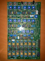
I’ve attached two pictures of the EQ and delay cards.
Giorgio
Attachments
Obvious first check is to rule out electrical circuit anomalies, new tweeters would still sound bad if crossover waveform distortion is the problem.Art, I believe that the internal EQ section has something like seven band parametric control, while the delay card is about the same complexity.
Probably a common replacement from CIARE could be adapted, thanks to the many calibration points, but the problem is which trimpot to move for a particular frequency and what sequence?
Without a technical manual, it could be very hard to find the correct calibration process.
If the response is actually calibrated for each driver used, the tuning process would require a specific measurement test jig to match a target acoustic response.
You could use your friend's freshly calibrated pair as a target response.
You could measure your amplifier(s) output electrical transfer function, record frequency response as set, then determine what the trim pots do by trial and error, likely frequency, amplitude and bandwidth for each band.
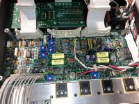
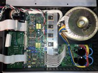
Charles, you might like to know that more NE5532 are used on the power amp card and one more on the input card.It is at least interesting to see that very high qiality active crossovers can be built using NE5532.
Regards
Charles
Attachments
Start by pulling the tweeters out and running an impedance curve on each one. Check that they are both smooth without any wrinkles. If there are wrinkles, then the ferrofluid has dried up or the VC is rubbing.
Even when working properly, this speaker has quite a bit of residual noise from the tweeter, due to the very large number of EQ and all pass filter op-amps in the circuit path.
Even when working properly, this speaker has quite a bit of residual noise from the tweeter, due to the very large number of EQ and all pass filter op-amps in the circuit path.
I have no experience with the HD1 other than having heard a pair setup in a small HT room.I agree Art, good idea to use my friend’s freshly calibrated pair as a reference.
The first thing I’ve to do is to check the frequency response of the units and see if what I hear is clearly visible on the graphs.
There is a John Meyer vid floating around where he talks about the HD1, that it was never intended to be a speaker for listening.
He said they built it to have a quick way to do measurement mic verifications in the field. IOW, all HD1s were meant to have exactly the same flat response, and if a transfer function didn't measure flat, the mic was off.
Then, some folks like the sound of them, and they became a regular product.
Maybe you've heard all that, but if not, thought it would be interesting.
Anyway, my takeaway is that you probably don't need to compare to anything other than a flat transfer function with a calibrated mic you trust...
Yes, I know the story. The HD1 was a different thing and had big electronics rack for the processing. It was intended as a calibration device for the microphones used with their SIM 1.I have no experience with the HD1 other than having heard a pair setup in a small HT room.
There is a John Meyer vid floating around where he talks about the HD1, that it was never intended to be a speaker for listening.
He said they built it to have a quick way to do measurement mic verifications in the field. IOW, all HD1s were meant to have exactly the same flat response, and if a transfer function didn't measure flat, the mic was off.
Then, some folks like the sound of them, and they became a regular product.
Maybe you've heard all that, but if not, thought it would be interesting.
Anyway, my takeaway is that you probably don't need to compare to anything other than a flat transfer function with a calibrated mic you trust...
Roger Nichols in sone way had the opportunity to listen the speaker and asked John to make a version that could be used as a reference monitor in studios. The rest is history. They also made the HD2 which used a bigger LF driver and a horn in place of the dome tweeter, but it was unsuccessful.
The HD1 was the first phase aligned studio monitor and probably also the first self powered monitor.
Hi Jack it’s what I’ll do.Start by pulling the tweeters out and running an impedance curve on each one. Check that they are both smooth without any wrinkles. If there are wrinkles, then the ferrofluid has dried up or the VC is rubbing.
Even when working properly, this speaker has quite a bit of residual noise from the tweeter, due to the very large number of EQ and all pass filter op-amps in the circuit path.
For now I can say that the movement is free and seems smooth. No wrinkles, as far as I can feel.
I have the proper instrumentation to track an impedance curve, just have to free some space on the desk…
Yes, some hiss is noticeable, but absolutely not disturbing from the listening position, even as near as 1m, and still incredibly low, considering the very high number of opamp stages involved.
They also made the HD2 which used a bigger LF driver and a horn in place of the dome tweeter, but it was unsuccessful
I once heard that one at the Montreux Jazz Festival where they used them in a lounge as mini PA for the live broadcasting of some concerts. Since then I am a fan of two-way speakers with horn.
Sorry for the OT.
Regards
Charles
Thanks for sharing your experience, Charles.I once heard that one at the Montreux Jazz Festival where they used them in a lounge as mini PA for the live broadcasting of some concerts. Since then I am a fan of two-way speakers with horn.
Sorry for the OT.
Regards
Charles
The HD2 weren’t that common, even during their days.
Giorgio
Those are hexfet outputs. Not the most thernally stable or linear power fet for audio duties, but with enough finesse and external safeguarding, it can be made reliable enough for pro audio duties. Lateral fets are better for this purpose, but i guess that's what they speced for their stuff.Charles, you might like to know that more NE5532 are used on the power amp card and one more on the input card.
Nothing wrong with NE5532s if they're implemented correctly. Those are older, original philips/nxp 5532s, which i prefer over generics.
Never been fond of Meyer stuff, although I do admire the old school approach. The ferrofluid they used back then wasn't very stable and often splashed or migrated out of the driver gap from hard use. Modern stuff uses Ester based FF as opposed to petroleum base, so you have to verify VC winding and adhesive compatibility before switching it out.
It took me forever to dig up these measurements that I took of an HD-1 in 1997. The first one is of the system on axis at 1M. The second curve is taken 30 degrees off a lateral axis, but displaced downwards 5dB. The second measurement in the impulse response from the on axis measurement. The system was on a 6' high stand, measured outdoors.
Attachments
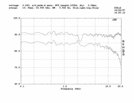
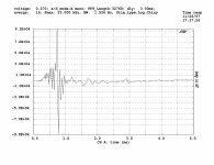
Thanks for posting your measurements Jack.It took me forever to dig up these measurements that I took of an HD-1 in 1997. The first one is of the system on axis at 1M. The second curve is taken 30 degrees off a lateral axis, but displaced downwards 5dB. The second measurement in the impulse response from the on axis measurement. The system was on a 6' high stand, measured outdoors.
The impulse response looks reasonably good for a so old design.
Giorgio
Thanks for the hint about FF.Those are hexfet outputs. Not the most thernally stable or linear power fet for audio duties, but with enough finesse and external safeguarding, it can be made reliable enough for pro audio duties. Lateral fets are better for this purpose, but i guess that's what they speced for their stuff.
Nothing wrong with NE5532s if they're implemented correctly. Those are older, original philips/nxp 5532s, which i prefer over generics.
Never been fond of Meyer stuff, although I do admire the old school approach. The ferrofluid they used back then wasn't very stable and often splashed or migrated out of the driver gap from hard use. Modern stuff uses Ester based FF as opposed to petroleum base, so you have to verify VC winding and adhesive compatibility before switching it out.
Today a friend informed me that the high frequency driver does not use FF, so it can’t be the reason of the issue.
Perhaps the dome and its suspension hardened or some debris is disturbing the motion inside the gap.
I’ve downloaded REW for Mac and will try it the next days. A good measurement is now essential to find the actual reason of the problem.
- Home
- Loudspeakers
- Multi-Way
- Meyer Sound HD1, looking inside