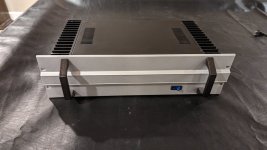
Some sound clips of this speaker recorded with my phone and powered by my
SuSyLu 100w Class A amp:
Test of SuSyLu 100W Class A Amp - YouTube
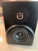
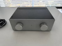
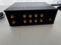
Example of speaker in dark “espresso brown” stain and satin lacquer with Duratex coated baffle.
Example of
beautiful build by as8912:
Another Example of a floor standing
FAST TL by Plott:
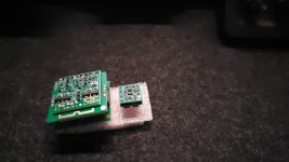
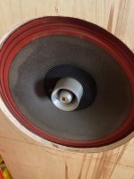
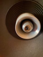
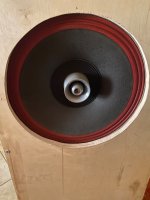
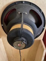
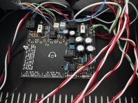
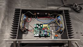
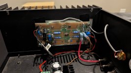
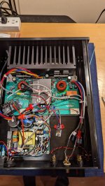
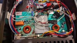
This is a great shot of the internals as provided by Plott:
Example of a floor standing TL version of this speaker by Moutik:
Example of a smaller sealed version with PS95-8 full range drivers by Jimk04,
here.
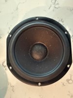
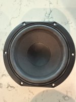
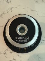
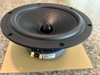
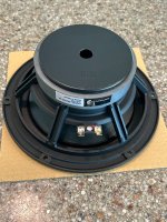
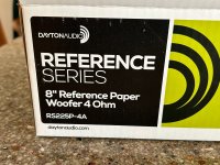
I wanted a speaker design worthy of the exceptionally high performing ScanSpeak 10F/8424 Discovery 3.5in full range driver. I decided that a short sealed Dagger TL coupled with a sealed bass unit would give me the best overall transient response and clarity. I decided to mate the 10F/8424 with the superb Dayton RS225-8 aluminum cone woofer for bass duties. The design ended up as a 24 liter volume for the woofer and a 1.1 liter 3-sided pyramid Dagger for the 10F/8424.
The important external dimensions are: 10.0in wide baffle, 7.5in CTC distance from woofer to fullrange, and 24 liter internal volume (sealed). You can make the height and depth to suit your individual case, but it will need to be deep enough to house the Dagger. The internal dimensions I settled on were 8in wide x 12in deep x 16in tall.
However, if you make it out of 18mm plywood like the ones I had my cabinet maker build - make the box using these dimensions.
Dimensions of sealed box version: most important is to make the width 10.0in (external) and CTC spacing between drivers 7.5in and adjust the depth and height so that you have about 24 liters volume. If you make it out of 18mm plywood it ends up about 18in H x 13.5in D. The 10F is located 4.5in top to center. You will need a rear chamber for tweeter (fullrange) so use a sports cone or wooded “Dagger” tall 4 to 5 sided pyramid. Stuff Dagger and main box with polyfill or fiberglass to taste.
New SketchUp Plans by
@jrKC for sealed version
here.
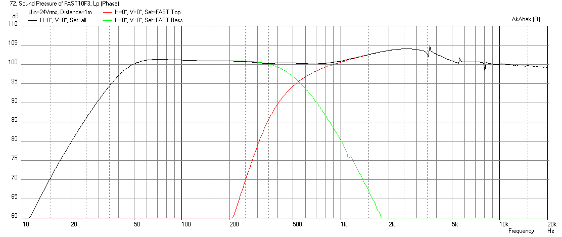
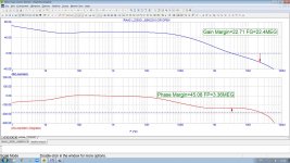
The short sealed TL is made of three 6in wide x 12.5in long triangles. Construction will use 1in thick pink XPS foam and regular foam core for the short TL. The front baffle will also use a thin sub-floor plywood in order to provide adequate support for the heavy 8in driver. The design will have the option of a bass reflex vent that can be sealed for use with a Linkwitz transform, or opened up for some additional bass when group delay is not an issue. The system will use miniDSP for XO and EQ duties and bi-amped. Here are predicted results in 4pi space with baffle step and diffraction effects accounted for. XO will be at 500Hz with 4th order LR. The RS225-8 is an exceptionally flat response driver and choosing a slightly higher XO frequency will keep the distortion on the 10F very low while giving more weight to the mid bass as it comes from an 8in woofer. Calculations show that with Linkwitz transform, bass extension should be about 42Hz (f3) with max SPL around 101dB.
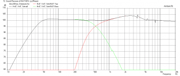
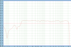
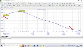
SPL vs freq for sealed case at 24v (no Linkwitz transform) - the hump at 2.5kHz is the baffle diffraction:
Impulse response for sealed case:
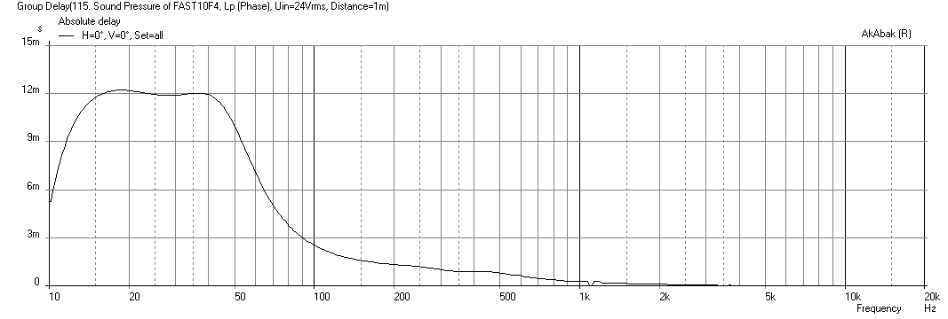
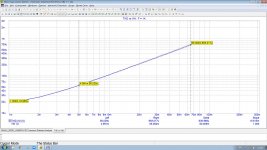
Group delay for sealed case is 2.5ms at 100Hz and 5ms at 50Hz:
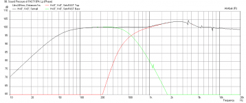
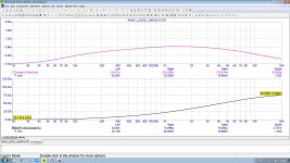
For bass reflex option, here is SPL vs freq at 24v:
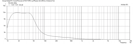
Here is group delay for bass reflex (2.5in dia x 11in long vent - rear firing) case, not too bad actually (about 10ms at 50Hz)
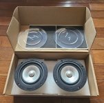
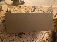
Here is the Sureply thin baffle with driver holes and drivers to show basic look:
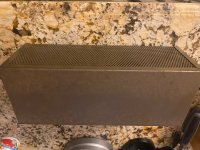
Here is construction on XPS enclosure beginning:
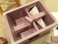
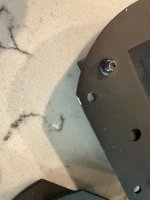
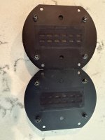
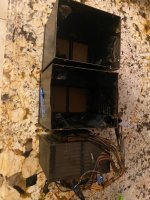
Here is the enclosure with Dagger TL internally mounted and bracing, wiring, and terminal cups installed:
Currently waiting for liquid nails glue to dry...
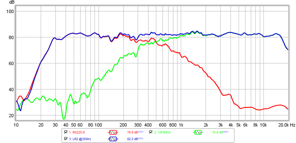
Edit April 27, 2015: New LR2 XO @350Hz and
new sound clips of many different genres. Have a listen, this speaker sounds fantastic!
10F/8424 & RS225-8 FAST Ref Monitor - Page 2 - diyAudio
Here is the new LR2 XO @350Hz:
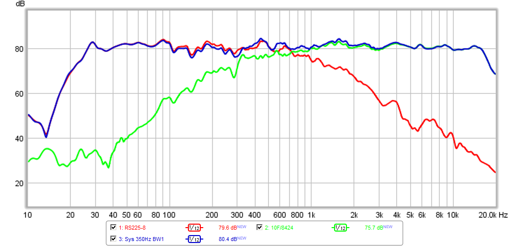
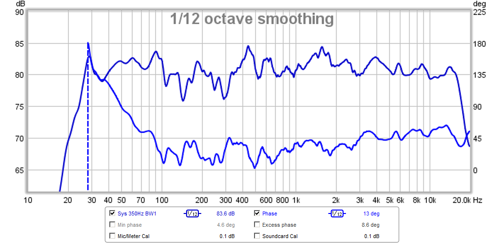
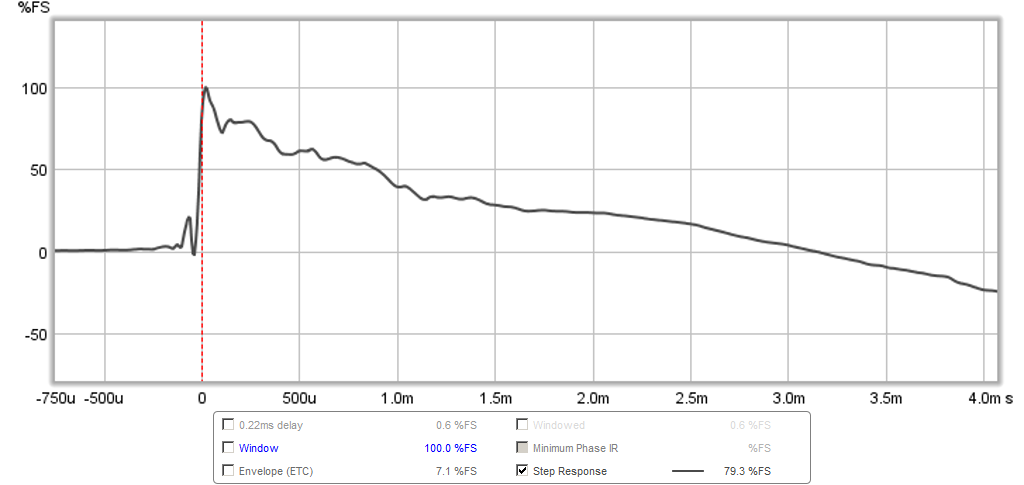
Update April 30, 2015: New Butterworth 1st order linear phase XO (BW1 XO):
Phase for BW1 XO:
Step Response for BW1 XO:
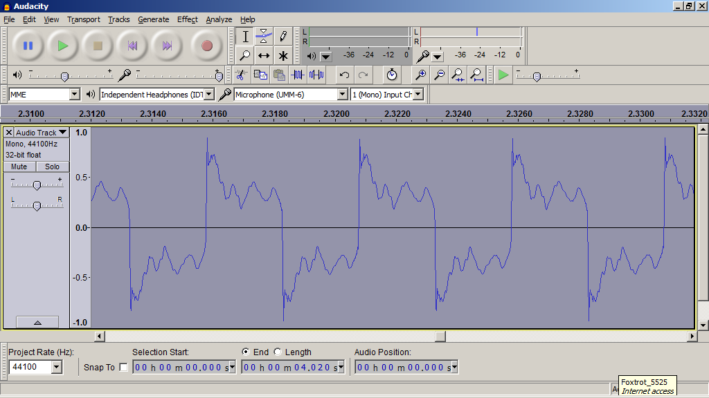
200Hz Square Wave with BW1 XO:
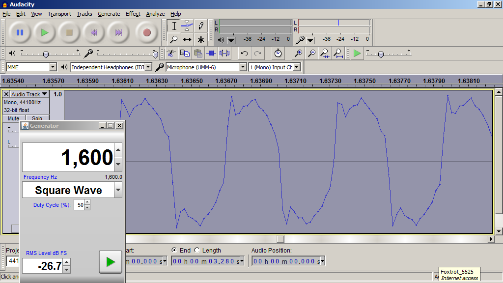
1.6kHz Square Wave with BW1 XO:
New sound clip with 1st order BW1 XO: http://www.diyaudio.com/forums/atta...or-10f-8424-rs225-8-fast-bw1-350hz-clip-b.asc
Edit May 14, 2015: Stereo Pair completed!
Edit Dec 16, 2015: forgot to post final lock-down configuration with Harsch XO:
IR:
Step response:
More info on final setup here:
10F/8424 & RS225-8 FAST Ref Monitor
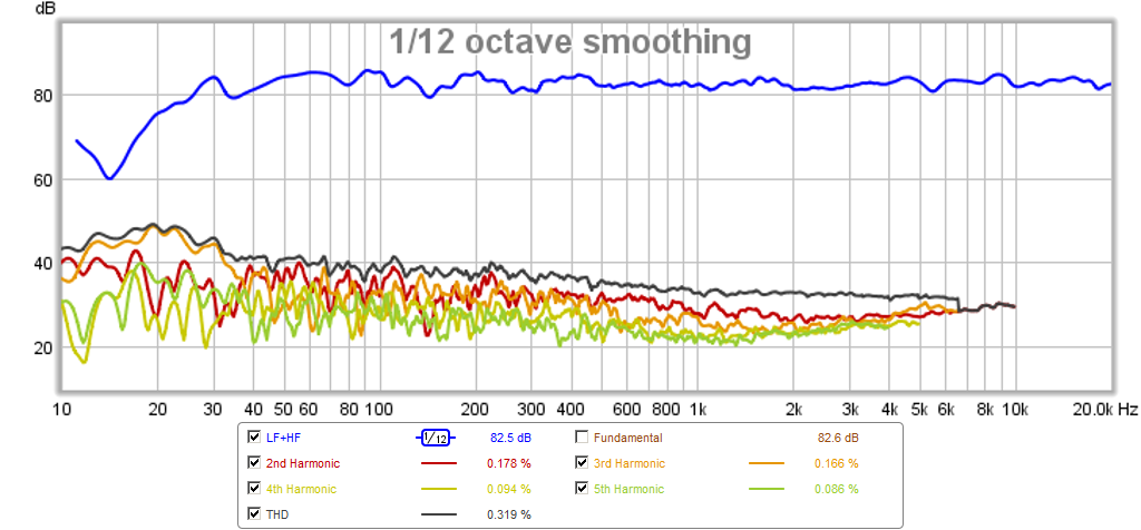
Distortion:
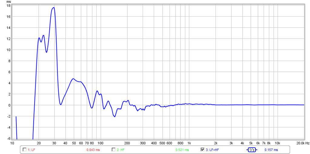
Group delay about 5ms at 50Hz:
Edit Jan 5, 2018: using passive 1st order transient perfect XO for past 2 years.
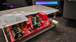
Recent implementation with film caps and air core:
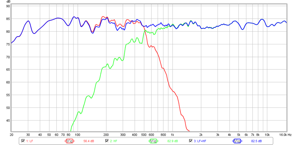
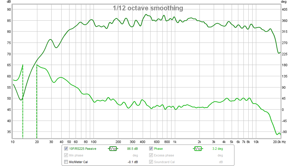
frequency response and phase using passive XO:
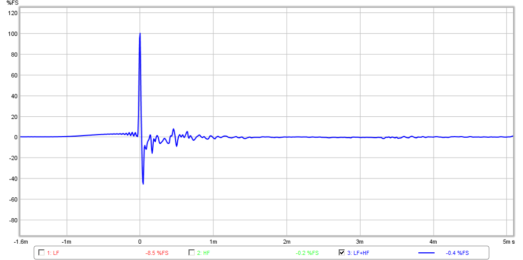
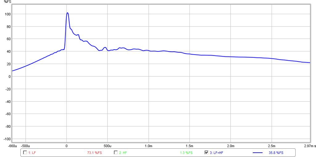
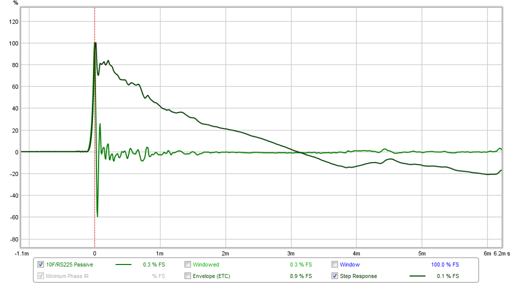
Impulse and step response:
Latest tweaks to the passive 1st order XO with simulation files:
10F/8424 & RS225-8 FAST Ref Monitor - Page 95 - diyAudio
Edit Dec 3, 2018: BOM for XO is
here.
Edit: Dec 27, 2018 - Wxn just built a pair using SB23NRXS45-8 and TG9FD-4 with DSP from a DCX2496
here. The results look great and he did a great job on the cabinet:
Nice waterfall:
Edit: Dec. 27, 2018 - I should have mentioned that Aatto built a nice set using the SB23NRXS45-8 with 10F/8424 as well but using a bass reflex box and miniDSP and also with passive XO, but can't remember what he is currently using
here:
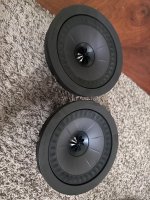
Also, forgot to mention the nice set with RS225/10F that I built in espresso brown stain - these are working out real well as the WAF is excellent as evidenced by the fact that they are upstairs next to the TV
🙂 :
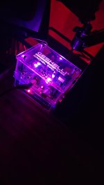
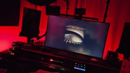
And of course, here is my current setup. These have been my main speakers for over 2 years now and, I keep coming back them because they sound so nice and balanced. The sharp percussion and wonderful stereo imaging also bring me back. Here they are in my speakerlab, now re-done post basement flooding (back in July 2018) with a new engineered wood flooring, so the echos are a mess and sound treatment is definitely needed now that carpet is missing. Looks nice and clean though - the clutter is building up again (mostly foam core speakers in storage around the corners).
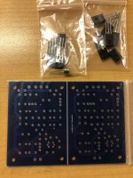
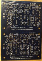
Edit Dec 16, 2019: Thanks to JPS64 for making a super layout for the XO PCB. This will make building this speaker that much simpler.
Edit Dec 21, 2019: new TL floor stander for RS225:
10F/8424 & RS225-8 FAST / WAW Ref Monitor
Measurements of TL
here.
Edit Dec 22, 2019: Just wanted to remind folks that there was a design made for this speaker XO with an RS100-8 and RS225-4 here:
10F/8424 & RS225-8 FAST / WAW Ref Monitor
Edit Mar. 20, 2020: Revised plans for the TL in all 3/4in BB plywood.
Photo of the TLs in action next to the sealed version:
Edit March 30, 2020:
Vistaton B80 Variant with modified XO
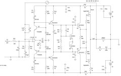
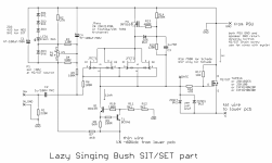
Edit May 19, 2020: this is the XO for the 4ohm RS225-4. You can use your favorite 8ohm 3.5in full range on top. Just make sure it’s 8ohms and adjust R1 to taste.
Edit July 24, 2023: Keantoken developed a crossover specific to the TC9FD-8 to be used in this speaker with the RS225-8. The response looks very smooth and has a wonderful step response. More info here:
https://www.diyaudio.com/community/threads/10f-8424-rs225-8-fast-waw-ref-monitor.273524/page-196
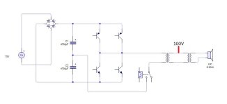
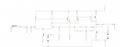
Schematic:
Measured frequency response appears to have 1st order XO near 1500Hz.
Nice stuffing/padding plan collected by GUJoe: