I bought a pair of these as basis for some experimentation.
I have listened to them a bit 'out of the box', but did not really like the sound. A bit harsh and a bit weak in the LF bass was the impression.
After some simulation, I have drawn the conclusions that the feedback DC cap could be increased (120uF), and so can the input cap (3,3uF). That could improve the bass slightly.
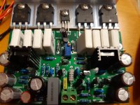
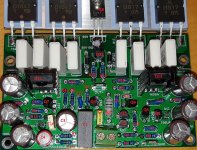
I put a 1000u bipolar for the feedback (to the left of the grey input cap), and soldered another 3,3u in parallel to the input cap on the back of the PCB.
From measurements I found that bias needs to be increased to reduce distortion. I added a 5k trimmer in the position seen on the picture and tuned it to the minimum Iq for lowest distortion at abt 1W. A value of 4,3k seemed to do it on both boards, and that resulted in a emitter to emitter voltage of abt 7mV, which translates to abt 16mA per output pair.
Distortion now stays below -100dB at abt 1W 8ohm. Improvement was abt 10dB with bias adjustment.
I have listened to them a bit 'out of the box', but did not really like the sound. A bit harsh and a bit weak in the LF bass was the impression.
After some simulation, I have drawn the conclusions that the feedback DC cap could be increased (120uF), and so can the input cap (3,3uF). That could improve the bass slightly.
I put a 1000u bipolar for the feedback (to the left of the grey input cap), and soldered another 3,3u in parallel to the input cap on the back of the PCB.
From measurements I found that bias needs to be increased to reduce distortion. I added a 5k trimmer in the position seen on the picture and tuned it to the minimum Iq for lowest distortion at abt 1W. A value of 4,3k seemed to do it on both boards, and that resulted in a emitter to emitter voltage of abt 7mV, which translates to abt 16mA per output pair.
Distortion now stays below -100dB at abt 1W 8ohm. Improvement was abt 10dB with bias adjustment.
Attachments
Last edited:

Some subjective conclusions on the above: caps did improve the low bass, but I still think it sounds harsh in the mid/treble.
I will plan for the next move. I have some ideas lined up, but not sure what to try next:
-high bias, aiming around 1A for class A at normal listening levels. (using fairly low supply voltage)
-replace output transistors with fast and linear ones (maybe reduce the number of pairs too)
-change (type of) compensation for greater LGBW (comes with faster transistors). Compensation scheme seems a bit odd to me as it is.
-possibly reduce OLG to get the dominant pole out of the audio band, around 1k as it is.
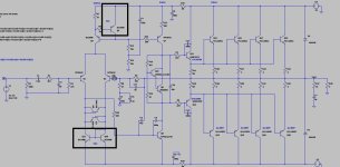
LJM has used some SMD components for the input CCS and current mirror on the IPS only marked fet1 and fet2, so these are a grey area in my sim, but I have confirmed the CCS current (0,65 mA!) so it matches my sim pretty well even if I used std transistors to substitute it. Another odd thing is there are no emitter resistors for the LTP or the VAS transistor. I'm also missing models for the driver transistors (KTC4370A/KTA1659A).
In general it's a blameless type amp with EF output.
I'm not sure if it's ok to post the schematic.. I emailed LJM and asked for it, promising not to post it if he shared it, but he never sent it, so I had to trace it myself from the PCB.
I have seen schematics/sims on some of his other of his amps here, so maybe this one could be made official too.
I will plan for the next move. I have some ideas lined up, but not sure what to try next:
-high bias, aiming around 1A for class A at normal listening levels. (using fairly low supply voltage)
-replace output transistors with fast and linear ones (maybe reduce the number of pairs too)
-change (type of) compensation for greater LGBW (comes with faster transistors). Compensation scheme seems a bit odd to me as it is.
-possibly reduce OLG to get the dominant pole out of the audio band, around 1k as it is.
LJM has used some SMD components for the input CCS and current mirror on the IPS only marked fet1 and fet2, so these are a grey area in my sim, but I have confirmed the CCS current (0,65 mA!) so it matches my sim pretty well even if I used std transistors to substitute it. Another odd thing is there are no emitter resistors for the LTP or the VAS transistor. I'm also missing models for the driver transistors (KTC4370A/KTA1659A).
In general it's a blameless type amp with EF output.
I'm not sure if it's ok to post the schematic.. I emailed LJM and asked for it, promising not to post it if he shared it, but he never sent it, so I had to trace it myself from the PCB.
I have seen schematics/sims on some of his other of his amps here, so maybe this one could be made official too.
Last edited:
Ok, I have done some simulation and soldering on these boards lately.
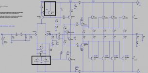
I will start this post with the original schematic etc. Please not there could be some errors in the schematic.
Loop simulations are not 100% because I don't have the correct models for the drivers and output transistors, but they will give an idea of the situation. The output models used are definitely higher Ft that the KEC transistors installed.
There is also a 'grey area' in the voltage reference for the CCS and the current mirror for the LTP. These are some SMD components marked fet1 and fet2 on the PCB, but I don't think they are critical. I have verified the currents by measuring the voltage drops over the resistors, and they are close to simulation.
Attachments
This is what I have done so far.. Aiming for high OLBW to get the dominant pole as far up in the audio band as possible.
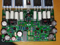
I replaced the small signal transistors with BC560 & BC546, since that's what I had in my stock, and they seem to be good for high frequency work. Adjusted gain with LTP emitter resistors. Increased the current in all stages, just because 'I want the current to be there' 🙂 In general it seems Ft goes up a it with current and heat too, so why not.
The output is also biased pretty hard, and I want to increase it even more with proper cooling if I go ahead and build a proper amp with more cooling. I like class A output operation for normal listening levels.
I replaced the outputs with 2SC2837/2SA1186 (high speed) and again I had some in my boxes. I have two pairs installed at the moment, might add another pair later. I actually have some 3281/1302 too, I have some freak idea of adding a pair of those with higher value on the emitter resistors, so idle current would be lower, but they would be 'helpers' at current peaks when hfe starts to drop on the main transistors.. They are also high Ft, but more linear hfe at high currents.. Thoughts on that?
I adjusted some resistor values for current increases, base resistors decreased for drivers, and base resistors added for the outputs. Input and feedback caps are also increased in value as mentioned before.
My current 'test bench' is a 'generic test chassis' with a pretty small transformer, double secondaries, double rectifiers and cap banks (2x10mF for each channel), +/-26VDC. A processor cooler with fan. It will not handle more than about 0,5A idle current because of heat and ripple, so that's where I am now.
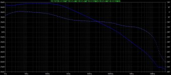
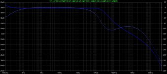
I attached the schematic and bode plot on mod1. The high value on C5 proved to give less overshoot on square wave testing, even if it could be smaller according to sim. I guess it dampens overshoot by HF-loading VAS via R29? Looked nicer on the scope when I increased the value. OLBW is slightly improved from std, and for all I can see it looks stable 🙂 Slew rate is abt 30V/us from measurement (no HF filters connected).
I have not measured the distortion, I have some issues with my Focusrite sound card, I think it was overloaded on the input in some measurements before. I have an ASUS, but the unbalanced input gives me issues with noise and ground loops. I guess I should order a new sound card..
I'm listening to it now, and I definitely like it better than before. I will give it some more time and decide if it's worth making into something, or mod some more maybe..
I replaced the small signal transistors with BC560 & BC546, since that's what I had in my stock, and they seem to be good for high frequency work. Adjusted gain with LTP emitter resistors. Increased the current in all stages, just because 'I want the current to be there' 🙂 In general it seems Ft goes up a it with current and heat too, so why not.
The output is also biased pretty hard, and I want to increase it even more with proper cooling if I go ahead and build a proper amp with more cooling. I like class A output operation for normal listening levels.
I replaced the outputs with 2SC2837/2SA1186 (high speed) and again I had some in my boxes. I have two pairs installed at the moment, might add another pair later. I actually have some 3281/1302 too, I have some freak idea of adding a pair of those with higher value on the emitter resistors, so idle current would be lower, but they would be 'helpers' at current peaks when hfe starts to drop on the main transistors.. They are also high Ft, but more linear hfe at high currents.. Thoughts on that?
I adjusted some resistor values for current increases, base resistors decreased for drivers, and base resistors added for the outputs. Input and feedback caps are also increased in value as mentioned before.
My current 'test bench' is a 'generic test chassis' with a pretty small transformer, double secondaries, double rectifiers and cap banks (2x10mF for each channel), +/-26VDC. A processor cooler with fan. It will not handle more than about 0,5A idle current because of heat and ripple, so that's where I am now.
I attached the schematic and bode plot on mod1. The high value on C5 proved to give less overshoot on square wave testing, even if it could be smaller according to sim. I guess it dampens overshoot by HF-loading VAS via R29? Looked nicer on the scope when I increased the value. OLBW is slightly improved from std, and for all I can see it looks stable 🙂 Slew rate is abt 30V/us from measurement (no HF filters connected).
I have not measured the distortion, I have some issues with my Focusrite sound card, I think it was overloaded on the input in some measurements before. I have an ASUS, but the unbalanced input gives me issues with noise and ground loops. I guess I should order a new sound card..
I'm listening to it now, and I definitely like it better than before. I will give it some more time and decide if it's worth making into something, or mod some more maybe..
Attachments

Last edited:
I found there is a break in the output line in my sims i posted, so if somebody would use it, please check that.
After some more listening, I think they sound pretty good, but bass control is not the best. Normal for a pretty low OLG amp I guess. Maybe bigger PS caps could help too. However, when simulating output impedance, I found that 'floating' the drivers emitter resistors from the output actually halved the output impedance. They will also keep working in class A. As it was, even with my increased standing current, they will switch off at high currents (5A peak). This will be the next thing I'll try.
Possibly I could even lower the standing current a little bit through them, even at 25A (peak) they will not switch off when not connected to the output.
I also have some ripple eaters that I'm thinking about trying.
@Rallyfinnen et al
OK, I realise tat this thread has become a little 'tired' but I find myself having to ask a question and this seems to be the best place to do so.
I have 3 x L20 V10 boards all with 0.1 Ohm emitter resistors and noticed that the schematic diagrams in this topic are showing 0.2 Ohm. Is this a known mod? The resolution on my DMM's isn't really good enough to satisfy my curiosity as to 2 what's installed so I may remove one and put some volts across it and measure the current, a bit of a PITA though.
Also resistors R15 and R16 in the schematic are different than those discussed earlier in the thread regarding bias adjustment??
Excellent thread BTW, keep it going..
Thanks all 🙂
Too long ago for my memory, these are stuck in a box somewhere now I think.. I recommend you get a used HK 670 instead (or whatever you like), complete amp with everything for less money and better quality (and sound). That can be modified too..
It's a nice allround sweet sounding amp with remote that you can get used for very little money. With some mods I found it to be a very good allrounder to drive passive speakers, decent power output.
Most bang (or SQ) for the buck I have come across when it comes to used amps.
I saw this amp on sale together with some Dali speakers for a good price, so I searched for the service manual online and liked the topology. I've wanted to build something similar, 3EF made for high current, for some time, and here it was using fast transistors etc. and a lot cheaper than starting from scratch The general design is nice too I think (ok maybe not the front plate), with channels fully separated, only a common transformer (with separate secondaries).
There was a slight hum, and I later found bad electrolytic caps in the low voltage supplies, probably because they are...
There was a slight hum, and I later found bad electrolytic caps in the low voltage supplies, probably because they are...
- Rallyfinnen
- Replies: 63
- Forum: Solid State
Most bang (or SQ) for the buck I have come across when it comes to used amps.
Indeed: bang for the buck, but I'm surprised that you've surrendered into buying an used amplifier after publishing a great deal of useful information and, correctme if I'm wrong, you've achieved remarkable results indeed.Most bang (or SQ) for the buck I have come across when it comes to used amps.
Right now Im back to the LJM business. I'm building all three the most recent L20 variants. My tests indicate that all three of them can beat HK670, at least on paper but all of them sound great too. I'm building now three great casings for all three of them. I know, that costs but the fun is all mine.😎😀
Last edited:
@Enterpryse
But ofcourse I will. It would be shame not to share information about this quality product. Observe please that @Rallyfinnen has already provided lots of information and yet there was lack of interrest.
Let's revive this thread!
But ofcourse I will. It would be shame not to share information about this quality product. Observe please that @Rallyfinnen has already provided lots of information and yet there was lack of interrest.
Let's revive this thread!
Well, it's a hobby, and that's why I kept buying all kinds of kits, building them and modifying them, thinking 'this is the best one so far' etc. I still have DIY amps I really like (Alpha Nirvana, Dartzeel, MX50), but most of them are in the bin, or scraps in boxes. No regrets, I learned a lot! When I started I knew basically nothing about amps. Why I recommended the HK is that I still really like it for what it is, I like the sound and it was cheap compared to most DIY amps I built.Indeed: bang for the buck, but I'm surprised that you've surrendered into buying an used amplifier after publishing a great deal of useful information and, correctme if I'm wrong, you've achieved remarkable results indeed.
Right now Im back to the LJM business. I'm building all three the most recent L20 variants. My tests indicate that all three of them can beat HK670, at least on paper but all of them sound great too. I'm building now three great casings for all three of them. I know, that costs but the fun is all mine.😎😀
The DIY amps I use are in my active setup, and I can use the amps for what they do best, or the impedance speakers they work best with.
I modifies many other cheap second hand amps too, but I did not like them in the long run. Usually I end up giving them away to friends and family. The modified HK980 I mentioned in the 670 thread (same circuit) sounded just as good, but I did not like the build quality, -lead free made in PRC. I gave it to my brother.
I still have some second hand amps lying around waiting for repairs/mods, but lately I have been spending more time with 2-stroke motorcycles.
Good luck with your build! I hope you all enjoy the hobby!
For me I think the best place to start is cross checking the PCB layout and the circuit diagram(s) against my received V10 board to secure a firm baseline for myself.
These are the diagrams I believe to be the baseline, or close to it. I'll report back 🙂
These are the diagrams I believe to be the baseline, or close to it. I'll report back 🙂
Attachments
@Enterpryse
Good plan
Meanwhile the both boards are again on the bench to repeat all basic meassurements. Then I plan to make three adjustments. Note that I'm talking about adjustments, not modifications. My objectives are modest meassurable and realistic. What I have observed LJM sets biass and feedback to conservative values to prevent us from turning the board into a smoldering pile of junk on the bench.
First I will change the feedback resistor to slightly lower its value to increase feedback, consequently to decrease distortion whilst keeping the amplifier stable.
Next, I intend to adjust biass current to possibly further reduce the distortion. This usually helps.
I plan to add a Zobel network at the output .
Diy chasis for this amplifier is almost finished.
That's all I plan to do. I'm sure that LJM has extracted the maximum from the chosen configuration. So no risky "clever" modifications, just adjustments.
Last edited:
If you agree I'll follow the numbering scheme by Rallyfinnen and add new numbers as required, then post them back onto this thread?? It might help reduce any ambiguity when readying the CCT diags.
🙂
🙂
Exactly! 👍If you agree I'll follow the numbering scheme by Rallyfinnen and add new numbers as required, then post them back onto this thread?? It might help reduce any ambiguity when readying the CCT diags.
First correction: Actual value of R16 is 5K1 (proposed schematics indicates 4K). The value of 5R1 is on the silkscreen and the delivered resistor is also 5R1.
First adjustment accomplished without problems:
1. Gain
R9 (33K) replaced with 27K. As expected gain has reduced from 33 to 27.4. Square wave response is normal, there are no signs of instability. I might go lower, to the gain of 25 to further improve distortion.
2. Bias
I have replaced R16 with potentiometer and have increased bias from the original (default) value of virtually zero to 21 mV. There are several suggested values, notably by Douglass Self. He proposed the value of 26 mV. Some other authors propose 11mV. There are no crossover artefacts after the adjustment. I will leave it at that value and try other values later, but I think that's it.
Bias should be meassured from the emitter lead of any output transistors and the signal output at the centre of the board.
Awesome....
I'm in the process of inputting the schematic into Kicad. It's a bit of a slow process as I've not used it before 😕
I'm in the process of inputting the schematic into Kicad. It's a bit of a slow process as I've not used it before 😕
- Home
- Amplifiers
- Solid State
- LJM L20V10 tips/mods etc