Hi!
Back with a Sony TA-F770ES. The pour thing has blown its output mosfets.
These 2SJ200/2SK1529 seem pretty close to the 2SJ115/2SK405 in the Luxman LV series that I successfully replaced with IRFP340/9240 with only very minimal modifications. I know from experience that these Sony amps can be pretty unstable, is there anyone that has tried this replacement before and/or can simulate what results this would give and if there are any mods that have to be done to the bias circuit for example ?
Thanks !!
those replacements are comparable assuming that what you have are legitimate 2SJ200/2SK1529. it is a risk because they have been out of production for several years now.
good luck,
mlloyd1
good luck,
mlloyd1
Actually, the 2SJ200/2SK1529 are the ones that are in the sony and that are blown, I would like to replace them with the IRFP340/IRFP9240 because I replaced 2SJ115/2SK405 (which are close to the 200/1529's) before with good results in a luxman LV-105U.
Did you find what caused the outputs to blow ?
Quite often outputs blowing take the drivers with them.
Quite often outputs blowing take the drivers with them.
Very good question this - it's not like MOSFETs would be blowing that easily. Not suffering from secondary breakdown tends to make them fairly robust.
Well the amp's not mine, it belongs to a friend. He bought it not knowing if it worked and hooked it up to a pair of suicide speakers. Problem was one of the speakers was shorted and clearly the protection circuit of the amp didn't kick in fast enough...
It's very likely there is more damage further up the stream but for now he just wants to know if it is possible to repair it for a reasonable price and these mosfets are my main concern.
It's very likely there is more damage further up the stream but for now he just wants to know if it is possible to repair it for a reasonable price and these mosfets are my main concern.
Hello again,
I tested all the fusible resistors and they're all within 1%. Drivers have been pulled and tested and they're fine as well. I do have one open 0.22ohm emitter resistor. The service manual says these are "Metal plate" resistors, would simple wire wound be fine here, or metal oxyde (these are the only two types available at mouser with these values).
I intend to replace the outputs with IRFP9240 and IRFP240 with the possibility that I'll have to modify the vbe multiplier slightly : in the luxman lv-104u in which I used these (and I'm not at the origin of this mod) it was necessary because the temperature compensation was way to important and cut bias in half after only a few minutes of warm up.
How did you get on with the newer IRF MOSFETS?
I have a sony TA-3000ES that has blown its MOSFETS (J200 and K1529)
Circuits pretty similar, they have doubled up MOSFETS for the one you are woking on...
Any recommendations?
I have a sony TA-3000ES that has blown its MOSFETS (J200 and K1529)
Circuits pretty similar, they have doubled up MOSFETS for the one you are woking on...
Any recommendations?
Attachments
It worked great with the new IRFP Mosfets, was very stable and sounded really good without any major modifications. I just modified the temperature compensation like on the luxman hybrid series. I'm not at home right now but I'll put up a little schematic of the mod. The bias drops a bit more as it warms up than with the original mosfets but way less thanks to the mod which consists of adding a second compensation transistor in series and place it somewhere away from the heat-sink.
The Bias circuit on your Sony seems slightly different and uses a different transistor so maybe the mod won't be necessary. Be careful with bias setting though, start low and monitor closely than slowly get up to spec setting. If bias drops too much after a few minutes of warm up you can try this :

Thank you, just demonstrates how much I don't know 😉
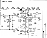
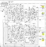
I love the way you made the cct 2D, Hadn't even realised the ccts were so different. Thanks for taking the time to draw it out.
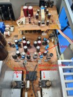
Q409 is'nt on a heatsink. See picture, I suspect Amplifier had been in a Barn for a while. Its not blowing fuses now all FETS removed. Botched fix with K405/J115 soldered onto old pins!. K1529 & J200 on other channel were bad, one shorted, other open circuit. Voltages seem ok, well consistanly at around 34V which is consistant with o/p from transformer.
I'm getting confused about BIAS and Vgs.
Vgs (Gate-Source Threshold Voltage) of the IRFP9240 is between -2 and -4V
and IRFP240 between 2 and 4V.
J200 and K1529 are between 0.8 and 2.8, with the "Y" variant between 1.4 and 2.8V
1) Am I over thinking this, how significant is the difference?
I love the way you made the cct 2D, Hadn't even realised the ccts were so different. Thanks for taking the time to draw it out.
Q409 is'nt on a heatsink. See picture, I suspect Amplifier had been in a Barn for a while. Its not blowing fuses now all FETS removed. Botched fix with K405/J115 soldered onto old pins!. K1529 & J200 on other channel were bad, one shorted, other open circuit. Voltages seem ok, well consistanly at around 34V which is consistant with o/p from transformer.
I'm getting confused about BIAS and Vgs.
Vgs (Gate-Source Threshold Voltage) of the IRFP9240 is between -2 and -4V
and IRFP240 between 2 and 4V.
J200 and K1529 are between 0.8 and 2.8, with the "Y" variant between 1.4 and 2.8V
1) Am I over thinking this, how significant is the difference?
Attachments
Last edited:
The little schematic I drew is for your amp but if the temperature compensating transistor isn't mounted on the heat sink you might not have the problem of it overcompensating with the new outputs. Isn't there anything directly thermally coupled to the outputs on that design ?
From what I see the Gate to source voltage is a little higher on you amp than on mine and it worked fine for me so I don't think this will be a problem. I really am no expert on Mosfets though so it might be wise to wait for someone else to confirm. Also check if your driver stage and fuse resistors didn't suffer from whatever happened. It might be wise to use a dim bulb also when testing. You can test if your bias adjustment works with it but make the final adjustment without the bulb because voltages may be lower.
Hope this all makes sense.
"Isn't there anything directly thermally coupled to the outputs on that design ? "
not that I can see
"Also check if your driver stage and fuse resistors didn't suffer from whatever happened. "
well voltages et all,without mosfets in circuit, seem to be ok
"It might be wise to use a dim bulb also when testing."
Already saved a lot of fuses 🙂, all good advice
not that I can see
"Also check if your driver stage and fuse resistors didn't suffer from whatever happened. "
well voltages et all,without mosfets in circuit, seem to be ok
"It might be wise to use a dim bulb also when testing."
Already saved a lot of fuses 🙂, all good advice
It worked great with the new IRFP Mosfets, was very stable and sounded really good without any major modifications. I just modified the temperature compensation like on the luxman hybrid series. I'm not at home right now but I'll put up a little schematic of the mod. The bias drops a bit more as it warms up than with the original mosfets but way less thanks to the mod which consists of adding a second compensation transistor in series and place it somewhere away from the heat-sink.
Hi @Depaj , I need to replace the output transistors on my TA-F770ES and I was wondering if you could describe exactly what changes you made in yours to get the IRFP replacements functioning correctly?
Thank you in advance 🙂
Hi!
This was a while ago but luckily I keep a lot of pictures. You can refer to the little drawing I posted in #12. What I did was replace the 2SC3423 with a KSC3503 mounted far away from the heat sink to reduce temperature compensation and keep the 2SC3423 mounted on the heat sink and connect its base and collector together (basically turning it into a diode) to the emitter of the KSC3503. So to sum up :
-Emitter of 2sSC3423 stays connected to its location on circuit board.
-Collector + Base of 2SC3423 connected together to emitter of KSC3503.
-Base of KSC3503 wired to previous location of the base of 2SC3423.
-Collector of KSC3503 wired to previous location of the collector of 2SC3423.
-Mount KSC3503 away from heat sink.
I also added a capacitor across the bias diode string for a little more stability : - to cathode of D412 (D462) and +to cathode of D405 (D455). I used a 4.7µF and it worked fine.
Make sure all fusible resistors measure ok and check the driver transistors and bias circuit components. Start with bias at minimum and slowly increase while monitoring oscillation if possible. I would recommend a dim bulb tester or variac to limit current in case something else is wrong.
@Depaj I cannot thank you enough. That is absolutely perfect and exactly what I need. I will order the new IRFs and KSC3503s and get soldering!
Do you happen to remember what bias voltage you set it to once you had finished? The original calls for 35mV but I guess it needs to be a bit lower here?
I assume no other issues with the amp since, and it worked and sounded perfectly?
Thank you so much again. I seriously appreciate it.
Do you happen to remember what bias voltage you set it to once you had finished? The original calls for 35mV but I guess it needs to be a bit lower here?
I assume no other issues with the amp since, and it worked and sounded perfectly?
Thank you so much again. I seriously appreciate it.
I think I did keep it at the original 35mV but I can not say for sure. I tested it pretty hardly on a dummy load even pushing a 1k square wave and it was perfectly stable. It sounded great as well. As I mentioned at the starting of the thread this amp was not mine and even the actual owner sold it later on but for the time he had it, it worked just fine.
Amazing. Thanks.
The KSC3503 is end of life and unavailable now. Would the MJE340 (https://uk.farnell.com/multicomp-pro/mje340/transistor-bjt-npn-300v-0-5a-to/dp/1574367) be a good substitute?
What sort of adhesive did you use to mount them to the chassis there?
Thanks again @Depaj !
The KSC3503 is end of life and unavailable now. Would the MJE340 (https://uk.farnell.com/multicomp-pro/mje340/transistor-bjt-npn-300v-0-5a-to/dp/1574367) be a good substitute?
What sort of adhesive did you use to mount them to the chassis there?
Thanks again @Depaj !
- Home
- Amplifiers
- Solid State
- Sony TA-F770ES output replacement