I was following Ian Hegglun's thread "Towards a wideband non switching Auto Bias power amp",
and I was inspired by one of his ideas - Alexander-type input stage and VAS based on op-amp LT1223.
I wasn't familiar with this op-amp, as it seems too fast for typical power amplifier.
There is no point to use expensive ($10.00), high slew-rate op-amp, just to throttle it
later on in order to make the amp stable.
But, if it's driving VAS not from the output, but via rails (like Alexander amp),
the whole amp is more stable and less temperamental.
This amp here shows slew rate of well over 200 V/us, and it's a very simple schematic.
My past attempts show that it's very difficult to actually build stable amp that
can achieve slew rates over 150 V/us. This is first amp I see, that shows phase margin over 75, and
also decent gain margin. In the sim, it seems to be solid, well behaved amp.
So I think I'll give it a try.
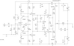
First, I came up with LatFet version (dual-die Exicons ECW20N20 & ECW20P20) - that's the one I'm
going to build, and later on with HexFet version.
Both versions show similar results in LtSPice.
Noise floor (1kHz FFT) is at -280dB, and all harmonics are below -120db (inaudible).
Update 29 March 2025: Based on the actual build, C4 should be removed. With it, amp had tendencies to oscillate (when using LT1223).
I keep it in the schematic, purely for the simulation purposes. Apparently LTSpice sim is slightly disconnected from reality.
Also, gate resistors have been changed to R2: 220 Ohm and R3: 100 Ohm.
Update 30 March 2025: If using different op-amp, C4 should be present (2pF).
The following op-amps have been confirmed to work correctly (besides LT1223):
LT1357, TLE2071, TLE2081, AD711, OPA134, LF356. These op-amps were not simulated in LTSpice, just confirmed that they seem to work OK
in the real amp. The schematic and sim may not be optimal for these op-amps, so there might be some space for improvement
if using non-LT1223 op-amp.
Update April 2025: Actual amp has been built and finished. See Post #47.
Update April 2025: HexFet version has been built and tested. See Post #55.


and I was inspired by one of his ideas - Alexander-type input stage and VAS based on op-amp LT1223.
I wasn't familiar with this op-amp, as it seems too fast for typical power amplifier.
There is no point to use expensive ($10.00), high slew-rate op-amp, just to throttle it
later on in order to make the amp stable.
But, if it's driving VAS not from the output, but via rails (like Alexander amp),
the whole amp is more stable and less temperamental.
This amp here shows slew rate of well over 200 V/us, and it's a very simple schematic.
My past attempts show that it's very difficult to actually build stable amp that
can achieve slew rates over 150 V/us. This is first amp I see, that shows phase margin over 75, and
also decent gain margin. In the sim, it seems to be solid, well behaved amp.
So I think I'll give it a try.
First, I came up with LatFet version (dual-die Exicons ECW20N20 & ECW20P20) - that's the one I'm
going to build, and later on with HexFet version.
Both versions show similar results in LtSPice.
Noise floor (1kHz FFT) is at -280dB, and all harmonics are below -120db (inaudible).
Update 29 March 2025: Based on the actual build, C4 should be removed. With it, amp had tendencies to oscillate (when using LT1223).
I keep it in the schematic, purely for the simulation purposes. Apparently LTSpice sim is slightly disconnected from reality.
Also, gate resistors have been changed to R2: 220 Ohm and R3: 100 Ohm.
Update 30 March 2025: If using different op-amp, C4 should be present (2pF).
The following op-amps have been confirmed to work correctly (besides LT1223):
LT1357, TLE2071, TLE2081, AD711, OPA134, LF356. These op-amps were not simulated in LTSpice, just confirmed that they seem to work OK
in the real amp. The schematic and sim may not be optimal for these op-amps, so there might be some space for improvement
if using non-LT1223 op-amp.
Update April 2025: Actual amp has been built and finished. See Post #47.
Update April 2025: HexFet version has been built and tested. See Post #55.
Attachments
Last edited:

Interesting amp design. I'll have to read Ian Hegglun's thread. For another NS amp, take a look at my nascent BEANS amplifier here:
https://www.diyaudio.com/community/threads/b-e-a-n-s-amplifier.423552/
It's quite complex, but does perform well in simulations.
https://www.diyaudio.com/community/threads/b-e-a-n-s-amplifier.423552/
It's quite complex, but does perform well in simulations.
In the past I've also experimented with variations on the Alexander CFB amp and gotten very decent results. His original design used a VFB opamp SSM2131.
In substituting a CFB amp the thing to watch out for in my experience is noise, in particular the noise at the -ve (inverting) input terminal. The noise current associated with this pin is - in my estimation - the CFB amp's 'dirty secret'. Note that the LT1223 tabulated data (page2) does not mention the inverting input noise current at all, the figures given are for the non-inverting input but that's not directly stated. Fortunately there is a graph later on :

The -ve input noise current flows through your R6 (910R) giving an effective voltage noise density of 18nV/rtHz at 10k but close to 100nV/rtHz at 20Hz. If your input sensitivity is 1V then it would suggest an SNR ceiling of 112dB at 10k but less than 100dB at 20Hz. Its a fairly simple step to reduce the feedback network (R6,R19) resistance to mitigate this. I note Ian Hegglun's schematic is using 220R for R6, reduced from an initial 2k2 so perhaps he discovered the noise penalty too.
In substituting a CFB amp the thing to watch out for in my experience is noise, in particular the noise at the -ve (inverting) input terminal. The noise current associated with this pin is - in my estimation - the CFB amp's 'dirty secret'. Note that the LT1223 tabulated data (page2) does not mention the inverting input noise current at all, the figures given are for the non-inverting input but that's not directly stated. Fortunately there is a graph later on :
The -ve input noise current flows through your R6 (910R) giving an effective voltage noise density of 18nV/rtHz at 10k but close to 100nV/rtHz at 20Hz. If your input sensitivity is 1V then it would suggest an SNR ceiling of 112dB at 10k but less than 100dB at 20Hz. Its a fairly simple step to reduce the feedback network (R6,R19) resistance to mitigate this. I note Ian Hegglun's schematic is using 220R for R6, reduced from an initial 2k2 so perhaps he discovered the noise penalty too.
Will try this..
I got very good results with this variation of Alexander amp:
I got very good results with this variation of Alexander amp:
Another week - another amp 🙂
One more amp built - this one has nothing to do with Wiederhold/LMK topology featured in this thread,
except the fact that is uses folded cascode.
This is variation of Alexander amp. I posted this schematic back in August 2021, and finally managed to finish it.
It uses the chassis with Mosfet output stage that accepts daughter-boards, and this is the 3rd amp using it.
PhaseMargin: 81 degrees, GainMargin: 20dB, SlewRate 90 (sim).
Op-amp used: LT1056. TL071 wasn't performing well in tests.
Output DC offset +/- 2mV.
I guess transistors on the input...
I'm very curious as to whether you experience a subjective improvement in bass performance through reducing the low-frequency noise.
Oh I also forgot to mention that there'll be an input offset voltage due to the CFB's input bias current flowing through the 47k (R10) and the amp may sound a tad noisy at LF without an input connected. With the input connected the AC impedance 'seen' by the +ve input will be much, much lower than 47k so the +ve input's current noise contribution won't be an issue.
Oh I also forgot to mention that there'll be an input offset voltage due to the CFB's input bias current flowing through the 47k (R10) and the amp may sound a tad noisy at LF without an input connected. With the input connected the AC impedance 'seen' by the +ve input will be much, much lower than 47k so the +ve input's current noise contribution won't be an issue.
I saw this approach for the front end back in the late 70's/early 80's and thought it was pretty clever. I built an amp or two using it and found they were pretty well-behaved in terms of stability. One scheme I came up with (and later found several other folks had, too) was to use a dual opamp and employ the other one in a tricky servo loop to reduce the output DC offset. That worked pretty good, too.
This also is a way to use a lower-voltage opamp. I've recently considered using the topology for that reason alone.
All the opamps I used were voltage-feedback opamps. CFB style opamps weren't really a "thing" back then.
I'm curious on how your amp performs. Please keep us updated.
This also is a way to use a lower-voltage opamp. I've recently considered using the topology for that reason alone.
All the opamps I used were voltage-feedback opamps. CFB style opamps weren't really a "thing" back then.
I'm curious on how your amp performs. Please keep us updated.
I have built a number of similar layouts. The first one with darlingtons in 1991. It delivered 25w in 8 ohms with 0,0008% distortion at 90% output. It used 5532 as OP for L+R. It worked better with ordinary output than using the power inputs.
I used the ordinary output from the OP and +. 5,6v feed via zener diodes. The first transistor pair with input to the emitters.
Now I have done a number of similar topics with OPA 1655 and Mosfets. I am not satisfied with the high frequency behavour because the mosfets needs more gate current for high frequencys.
I expect your amplifier to reach about 10v/us full signal with that large resistors to the gates.
You could try the OPA 891 too.
One of my previous amps with exactly same latfets and gate resistors (and slower VAS/op-amp) reached 60V/us (measured).
Of course we could use lower values for these resistors if amp (real build) stays stable...
That previous amp works very well, measures very well, and I like the sound.
Of course we could use lower values for these resistors if amp (real build) stays stable...
That previous amp works very well, measures very well, and I like the sound.
Here is a little, simple amp that turned out to be easy to build,
and with decent parameters.
It's based on Philips AH578 (which was a quasi amp), originally designed by Earl Rapp, but built with modern devices (LT1056 op-amp, Exicon dual-die FETs). Rails at 45V.
All screenshots taken with 8 Ohm load.
DC offset at the output: 2mV, and stable.
Idle current: 80mA per device.
PCB design: post #13
HexFet version of the amp: post #124
PCB design for HexFet version: post #130
Push Pull HexFet version (fast and stable): post #1
...
- minek123
- Replies: 202
- Forum: Solid State
Last edited:
Here is one of mine testcards. Has alot of similarities with your old amp.
There are some changes i had to make as the negative supply for the OP is to low.
All small capacitors had to change to get it stable and it still had a little bit to much distortion. C10 and C11 had to go.
But thermal compensation was good with T9 on the heat sink - a little bit much but good.
Stability is made with the principle of nested integrating feedback loops - but a bit changed.
That always was my concern. I connected a small capacitor across the opamp's +/- supply pins when I was fooling around with the scheme.It looks interesting and promising, and I look forward to the physical implementation.
In particular, I am curious to see how a fast opamp is going to behave with non-zero impedances seen by the supply pins
@stigigemla - these are hexfet outputs (if I can trust my eyes), and there is no drivers as far as can tell, correct?
No wonder you needed more gate current... Hexfets need drivers, they don't sound good without drivers, I tried it..
Lateral fets behave much better in this aspect.
Also, I see 3 feedback loops (global, op-amp, and from VAS to the output of the op-amp). It didn't work with only one or two?
No wonder you needed more gate current... Hexfets need drivers, they don't sound good without drivers, I tried it..
Lateral fets behave much better in this aspect.
Also, I see 3 feedback loops (global, op-amp, and from VAS to the output of the op-amp). It didn't work with only one or two?
Last edited:
It looks interesting and promising, and I look forward to the physical implementation.
In particular, I am curious to see how a fast opamp is going to behave with non-zero impedances seen by the supply pins
Am I correct, that we are facing the same situation like in your current dump amp where 2nd op-amp is floating?
It also has to deal with non-zero rail impedances, I guess.
That amp was rather slow, let's how this one will behave..
Yes, and it was not easy to stabilize, but I don't know whether the opamp configuration was the root cause or other factors came into play
Yes they are hexfets. I have tried trenchfets too but they work similar. Higher input capacitance but higher transfer sensibility (S) and lower output capacitance.
So the art seems to be to maximize gate current for them.
But sounding bad i wouldnt say. I have distortion less than 0,001 % with them.
I just want go go under the 21 bits = 0,00005% dist.
With 2 integrating feedback loops after each other you have a roll of of the open loop gain of 24db / octave.
That means with a bandwith of just 1 MHz you will get 100 x 100 open loop gain at 10 kHz.
With the phaze shift of 180 degrees you have to balance it with 90 in the outer feedback loop.
The open loop gain is comparable with a bandwith of 100MHz and a single feedback loop 10 kHz. Thats very hard to make.
Now the patent doesn't seem to be valid. (I believe there are op:s using the technicology older than the patent)
And now it is easier to find it under ("nested Miller integrators").
One of my previous amps with exactly same latfets and gate resistors (and slower VAS/op-amp) reached 60V/us (measured).
Of course we could use lower values for these resistors if amp (real build) stays stable...
That previous amp works very well, measures very well, and I like the sound.
The simulation shows that gate resistors can be safely halved in values (220 Ohms + 100 Ohms) without making the amp less stable.
Will experiment with these values in the real build - if slew rate is indeed too slow with current values.
PCBs finally arrived, and the amp is almost ready for testing...

In the sim (see post #1 pictures) it's very stable.
Will do my best to try to test the prototype this weekend....
Will do my best to try to test the prototype this weekend....
- Home
- Amplifiers
- Solid State
- Fast MosFET amp with LT1223 opamp front end