Hello from a newbie

Hello diyaudio community. After wandering the wilderness of diy audio, what a treat to find this community.
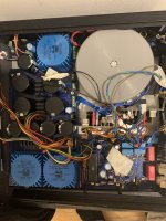
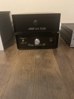
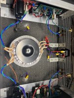
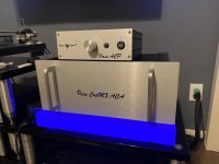
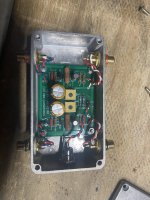
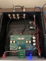
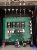
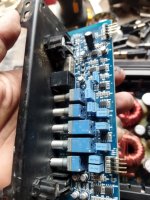
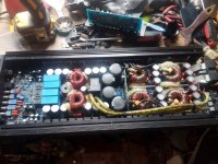
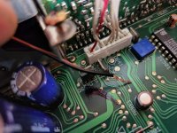
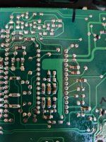
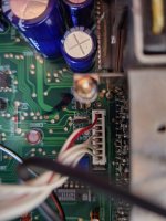
I have constructed a couple battery powered HPA's. I also constructed a G. Randy Slone power amplifier, including etching the PCB's myself. I haven't gotten the power amp up and running yet. The fuses blew when I powered it up so I shelved the project for awhile. I still have hope for it.
What a treat to find this community of builders. The knowledge base here is inspiring. I hope to learn more about this craft. Thanks for having me. Dave M.

Precision Power a600.2 Blown Channel Help

Hello, I have a PPI a600.2 amplifier that recently has had some issues. I believe that I ran too much power, causing a channel to blow. The amplifier still plays one of the subs at a very low volume, but there doesn’t appear to be any hissing. I’ve read that the cards go bad on these amplifiers, however I don’t have any experience working on amplifiers.

I’m attaching pictures of the board to see if anybody can help point me in the right direction. A few of the transistors seem to be replaced, meaning the board was worked on, however I’m not sure what could have went wrong this time.

If anybody could help it would be much appreciated!
B9F0F464-30A3-47E7-8F33-3B3C5F68FA4A.jpeg
D5E88B26-BC35-4B53-A774-CF2B66AE4769.jpeg

7193/6SN7 + 6V6 preamp

Hi friends
I want to build preamp consist of 7193 or 6sn7 at the Input as a driver for 6V6 which will be at the output stage.
Do you know any very successful design based on those tubes ?
Regarding to the power supply I have red comments that CLC sounds more natural and dynamic if high quality chokes is used like AN HIB core next to tube shunt regulator that can create noise.

I would appreciate any reply and help

God bless you all.

P.s
This is my first tube project

Direct PWM Output to a PowerStage

Hi,

I hope the Question is not to stupid and I’m in the right Subforum.


I’m looking to drive 3-4 Channels per Speaker Box with an AMP that’s fed with PWM at 384kHz (352-500kHz).
Is there any Way to either use ADAT or files/network to get directly to a good PWM Output for a Power Stage?
I mostly see: X -> I2S -> PWM -> PowerStage

Is there a μC with direct Output of 3+ PWM Channels that are good enough to be directly fed to the PowerStage?
TI has three "eHRPWMs" in their AM335X Sitara. Would they suffice or is there some special reason to add a I2S-to-PWM Chip?

I guess I need at least Hardware PWM and DMA to even consider it for Audio?

The Sitara could receive ADAT, use a Network and access local Files.
(Additionally the Sitara even has DSP Functions.)

48kHz@16bit is needed and 96kHz@16bit would be nice.
I guess I won’t hear any Difference for higher Sample Rates or higher Bit Depths.


Thank you very much.

Technics SU 3500 different problems

Hello.
Integrated amplifier TECHNICS SU 3500.
Some problems.

Preamp white noise on all sources volume on zero.
Power amplifier protect mode.
All transistors (power transistors and driver )
dessoldered tested and are ok.
Two or one power board Amplifier connect...... protect mode.
Not connected 2 or one power board Amplifier works fine(preamp).
But white noise....
The sound is very good (on preamp),but with white noise.

SM
https://elektrotanya.com/technics_su-3500_service_manual.pdf/download.html

FS: Pioneer 12" Woofers (4)

New $90/ea, Mine $90/pr or $160/all4. You pay shipping.
Clean, authoritative, deep to maybe 35 depending on tuning.
I wouldn't use above 700 or so, nasty peak at 1k but smooth below that.
Never abused, Hi-Fi only, but you can seriously boogie with all 4.
Specs below pix.
DM to ralph james at bell south dot net. (remove spaces)

Pioneer Front.jpeg

Pioneer Back.jpeg


Pioneer A30IR50-51F Specifications:
• Power handling: 150 watts RMS/210 watts max
• Voice coil diameter: 2-1/2"
• Impedance: 8 ohms
• Frequency response: 19-5,000 Hz
• Magnet weight: 50 oz..
• SPL: 91 dB 1W/1m
• Vas: 11.91 cu. ft.
• Xmax: 3.1 mm
• Qms: 4.37
• Qes: 0.27
• Qts: 0.25
• Fs: 19 Hz
• Net weight: 10 lbs.
• Manufacturer model number: A30IR50-51F
• Dimensions: Overall diameter: 12-1/8", Cutout diameter: 10-7/8", Depth: 5-1/2", Magnet diameter: 6-1/4", Magnet height: 2".

Transformer output in phase and out of phase

Hi everyone,

Can someone please explain to me the following principle:

I own an Electrocompaniet Ampliwire IIA amplifier and I am working on improving the power supply.

That transformer used has four secondary outputs per side and when checking the phase of the windings I discovered that two of the windings per side are out of phase.

I first thought that someone before me had modified the amplifier and had by accident wired some out of phase,
but after checking several other amps I discovered that it appears to have been manufactured that way.

I always thought that a transformer should be connected in phase, where comes my surprise in discovering this.

Does anyone have a logical explanation for a connection to a bridge rectifier that two of the four windings are out of phase with each other?
What are the advantages and disadvantage either one way or another?

Thank you in advance for any response you may have that would enlighten me.

I include a wiring diagram showing how the windings are connected on each bridge rectifier.

Attachments

  • Diode Bridge Connections.jpg
    Diode Bridge Connections.jpg
    143.1 KB · Views: 239

What are your best practices for making full range speaker systems!

I am embarking on making some full range speakers and there are tidbits here and there but I would really be interested in the communities best practices for designing full range speaker systems, building the crossovers and enclosures. There are some general universal truth's (are they so universal?) I will list below, but what are YOUR go to things that you do every time or have seen a lot of people use.

1. No cubes in the enclosed space! Is this universal? Has anyone had success with dampening materials or adding non parallel spacers to break up internal resonances?
2. No cheap crossover parts!
3. Horns are very directional
4. Enclosure material doesn't matter as long as your baffle is 1" thick, this seems to be the consensus that I have seen, and sides are at least 3/4.
5. Limit baffle area (yet I see tons of loudspeaker companies have baffles, for cost reasons?)
6. Don't mount speakers in the middle of the baffle
7. I see a lot of ported subwoofers its almost a standard, or passive radiators to get those very low frequencies.
8. Measure your speakers inside your built and finished enclosure to design your crossover, don't use just electrical parameters (makes sense)

I can't think of too many more, what I would consider, standards about making full range designs. Maybe you have some rules around what kind of tweeters and mids are best in terms of materials, brands or some trick to the trade to identify the garbage from the good stuff. Maybe you have built a lot of crossovers and have some tips and tricks around some estoeric things such as helping with impedance or using multiple parallel resistors vs one large one, something like that! Maybe you make all of your enclosures in a certain way, or always use felt on the outside, I have seen some interesting things!

What are your best practices?

Using Logitech Z-680 without pod

I am a complete newb when it comes to this, so bear with me. I am trying to learn as much as possible about hacking my Z-680 amp, so that I can use the sub and speakers with the original amp without the pod.

This page: http://www.diyaudio.com/forums/chip-amps/26714-logitech-z-680-a-6.html#post615079 down at the bottom has the best explanation I've found. But being that I'm a newb, I can't figure out how to actually do step 4 and 5. I want to connect it to my PC. After much researching on how 1/8 TRS jacks are wired and such, I think I sort of figured it out, but I want to be sure. I'm assuming that I can use 1/8 TRS plugs to connect to my sound card directly....

Any help would be greatly appreciated.

Does anyone have contact info for whoever runs Hifiengine?

I had an account for years and it got banned about one year back; never understood why. So I opened a new account using a different email address I have. It worked for several months and now I'm banned again.

I need to message whoever runs this place and sort it out, but there's no contact info at all on the site - weird. Also weird - I see no way to donate to the site, which I would be happy to do but they provide no means to do so.

Thanks for any clarity you can provide!

How to reduce noise on PowerSupply or Amp PCB

Hi,
i had made my own composite Amp with the LM3886.
The Amp runs very stable under all conditions.
Also the THD is ok for me , in a unbalenced ,direct input using of Signal and GND.

But , all if I try , i do not get a better noise, all under FRQ below the Test 1Khz tone is bad...

If I use a regulated PSU , the Noise is also... if I drill +,- and Gnd it becomes better.
The PSU I made is from a "Ringkerntrafo" mit 40.000µF each and a Ripple Eater,Snubber ... so the Vcc to the AMP is very very clear.
So less Ripple, but much noise.... I do not use fast Diodes , I use Bridge Rec. for smooth acting.

Attached , you will find the measuremts diagramm: Input for 10W @ 4Ohm Load

I think the 100 and 200Hz could be a typical Effect, but which one.
I also try with common mode chokes in line of PSU, no bettter result.


I will be lucky for each Tip.
2th_pcb_1khz_10W.jpg

Help needed for My_Ref Fremen Edition , Download folder in Google Drive are not more active

Dear all, I tried to download the Google Drive Folder of the

My_Ref Fremen Edition GB (13th GB) Board.​

But the Folder is forbidden.

I also write to Mr. Fremen, by PN , but unlucky he don´t answer me.

Has anybody of you in this Forum the latest release schematic and PCB and all other Data from his old public link ?

Here the Link of the Post and there is the Goggle drive folder.
The Link for the Google drive you found there direct under the latest THD measuremt diagramm
direct in the first Step of the Topic

https://www.diyaudio.com/community/threads/my_ref-fremen-edition-gb-13th-gb.330082/

kind regards
Michaela

TAS5706 simple full digital stereo amplifier

Now TAS5706 amplifier is playing great music from small board 🙂

I think TAS5706 can be final solution for Stereo Full digital Amplifier for DIY.

please see my website for detail, and hi res photos.

If anyone want to be group by manager, I can provide ExpressPCB CAD data. ( I don't want to be.. )

Attachments

  • p1010292diyaudio.jpg
    p1010292diyaudio.jpg
    96.8 KB · Views: 2,893

LED keeps blowing on AC supply

I think I know why but throw it out to the analogue experts.

I am powering a 3mm blue LED from an 24 V AC power supply with a drop resistor, circuit digram below. After a while, maybe 30 minutes, the LED blows.
According to datasheet, the max reverse bias is 5v, anything above reduces the lifetime of the LED.

When the LED is reverse biassed, the voltage is shared across the doide, resistor and LED with very little current flowing - to actually determine the voltage across the LED requires looking at the V-I graph for the diode and LED. I expect that when the current is determined, the voltage across the LED exceeds its maximum.

Attachments

  • led ac.jpg
    led ac.jpg
    26.9 KB · Views: 222

FS: "Fast, Fun, Inexpensive OB Project" - "Manzanita-like" Speaker - Wash DC Metro

FS: "Fast, Fun, Inexpensive OB Project" - "Manzanita-like" Speaker - Wash DC Metro

Selling a pair of open baffle speakers based on what might be one of the longest threads at this site (2,600+posts).

These aren't very efficient (approx 80-ish db) - but can produce some seriously good sound for the money.

Asking $300, which is basically the cost of parts. The woofers and tweeter are all currently out of stock for the next month or two.

These were built using 18mm 13-layer Baltic Birch plywood + solid Koa wood sides.

I've included some pictures below, as well as measurements (gated - so please disregard below 500hz) to the left and right of the speaker, and well as the average response from -30 to +30 in the horizontal window.

For sale in the Washington DC Metro area only.

XJDkTw5.jpg

RyfqjGW.jpg

xNc9iO3.jpg

vZrtfcM.png

tsc4qdN.png

jth1qDT.png

Port Tuning

Hello,
Long time lurker, first time poster. I was wondering if I could get some advice on where to tackle issues i'm running into with building ported boxes:

The boxes I've been making to WinISD's spec seem to always (8 or 10 attempts) have the port tuned 5-7 Hz lower than expected. I'm using online calculators to proven alignments and drivers recommended in appropriate enclosures as a starting point.

My attempt:
I'm starting with an Eminence Kappalite 3015LF, recommended volume of 3.2 cu ft, modified port size but same tuning frequency (53 Hz). Port calculations seem to be consistent across the different calculators I've tried in spot checking my work; this leaves me with volume/loss/driver calculations being the root of my problem.

I account for internal volumes with a homemade calculator accounting for drivers, ports, braces, adding back any holes made to attach said objects (like driver holes). Recently I've added a 3% fudge factor to reduce the volume to account for losses and still coming up short on frequency targets.

Attached is the impedance graph from the latest design. The box is the recommended size, adjusting for internal displacement, and an attempt at a 53 Hz port. It started out at 46 Hz and shortening the ports (and enlarging the box) got me to 49ish Hz. 5 of the 6 sides sides are braced with truncated-triangular braces and 2 sides padded with 1 in acoustic foam.

The results are ok, but in attempts to pursue perfection (and willing to accepting 95% of it) I'd like your (collectively) take on how to approach this problem to improve my understanding and produce less scrap in the process on future builds. Thanks for the help!

B4 Alignment.jpg

FS broken Hypex UcD amp build with enclosure

Hypex 2x UcD 180 build with high performance PSU (discrete diodes, multiple power stages and PGA preamp (got from a friend). One UcD180 module has a blown cap.

You could salvage the nice all aluminum enclosure, the PSU and one Hypex module or re-build the amp. I have no time to work on this project any longer.

Asking for 130 Euros plus shipping. I can ship to anywhere in Europe (or local pickup in Austria).

Attachments

  • image.jpg
    image.jpg
    588 KB · Views: 177

Site to buy allready cutted pannel for subwoofers.

Hi,

around on the 2015 I was building a sound. I've downloaded the pdf and start taking all the dimensions. I don't know if was my fault or on the pdf but at the end some panels was wrong. I've said that was best to have all the plans draw in 3d.

So I made Speakerplan Archive using the pdf of other project that I've found free online. After some years I have the idea to sell the already cut components with cnc.

Now I upgrade that site with a new site which is a Gig economy project.

The site is www.speakerplanbuilder.com, but you can reach it from speakerplans.eu for now.

Here you can buy pre-cut components or build a sound system and sell it to another.

I am looking for artisans able to do this job in It,Fr,Ger,Uk and Usa.

Is somebody intersted?

Let me know.

DD

Attachments

  • qqqq.JPG
    qqqq.JPG
    103.3 KB · Views: 93

Meatgrinder Sub

Guys,

I'm trying to replicate the Meatgrinder sub, created by Amano here: 2x18" MEATGRINDER v2 (done!) - Speakerplans.com Forums - Page 12
I think it's based on the Martin Audio WSX.

Unfortunately there are no plans as such so trying to do this from scratch but i really don't know how it'll work out!

I just wanna find out the purpose of closing the baffles 2/3 of the way like he has? Doesn't this restrict air flow and also wouldn't the sub start pounding on the wood?

Attachments

  • MG218 3d.jpg
    MG218 3d.jpg
    46.4 KB · Views: 1,058
  • 5.png
    5.png
    295.5 KB · Views: 731

Power dissipation in tubes, where is it occurring?

Just a thought...I mean, I know the plates are the hot parts in the tube and we have the plate dissipation. I may have a brain fart at the moment, but thinking about the workings in there...
The metal plate inside the bulb surely has no voltage drop. (ok a few uV perhaps). (I am thinking if you could measure the ends of the plate inside the vacuum tube). The voltage drop is between the plate and the cathode, that means the voltage is in the vacuum, the space between the plate and cathode. But surely vacuum cannot be heated from current running thru it?
I understand the plate gets heated by the bombardment of electrons and the current running thru it. But since there is no voltage drop on the plate, is all the heating due to bombardment of electrons?

Probably a confusing question. And I am only asking out of curiosity, I am not worried about tube design, but for some reason I want to understand this a bit better (obviously I dont understand at all).

USB to DIG OUT

In 2011 I made a USB to Dig Out gadget from an article in Elektor magazine of Sept of 2011. It appealed to me as I was just getting more into the possiblities of streaming and the cost was so cheap I had to give it a go. You need a cheap USB sound card which is CM108 based and they are still readily available for a few $s or £s. I hadn't used it for a couple of years having Dacs which accept either a 2.0 or 3.0 USB lead but thought I would give it another airing. It can handle up tp 96kHz which these days is no great shakes, but it is really pretty good and I thought it may appeal to others as a weekend project for fun.

The link is for the whole magazine, but the article is on pages 67 - 69.

https://worldradiohistory.com/UK/Elektor/10s/Elektor-2011-09.pdf

Help with Induction heating for steam

Hi,

I'm working on a project that would require the ability to heat water into steam via electric induction, preferably DC or via AC converter if necessary.

I'm thinking a monotube design with an induction coil surrounding it that could produce steam from 2 quarts of water in say 30 seconds or less.

Anyone here have experience with that kind of design?

Thanks,
🙂

JL Audio A1800

Amp came in with blown power supply fets and outputs .
After replacing the fets , drivers,gate resistors I checked the drive signal .

Is it normal to get a square wave on the gate and drain legs ?

Attachments

  • 05AF1FBC-28A5-4DE4-8F42-38D9DB746DE6.jpeg
    05AF1FBC-28A5-4DE4-8F42-38D9DB746DE6.jpeg
    650.9 KB · Views: 146
  • 6BD949C8-5D52-44C5-ABFB-5D35625C1AA6.jpeg
    6BD949C8-5D52-44C5-ABFB-5D35625C1AA6.jpeg
    715.8 KB · Views: 136
  • 144FF49F-AF3A-46FB-BDCF-5F24738AD0BE.jpeg
    144FF49F-AF3A-46FB-BDCF-5F24738AD0BE.jpeg
    772.3 KB · Views: 180

Soundstream VGA Van Gogh 400.2

Is there a schematic available for these style amps? Ive seen a few this style, and all needed service around the drive/regulation circuit, 27v Zener diodes I believe. This one amp does not however and so this is a new issue for me.

What this one has is a problem with either RCA shields or secondary ground float. The RCA shield LED blinks rapidly no matter the source (Common, grounded, floating), and the output on speaker terminals passes audio but is jumping all around. I believe this amp also blew a 12" subwoofer, and may have been sliding around in a trunk at some point.

I've cleaned and tested ALL switches, cleaned all potentiometers. Treated with Deoxit all daughter board connections. Rail voltage looks good, regulated voltage looks good. There are no damaged visual areas and all components seem tight. I pressed and tapped on a LOT of components and no change at output/RCA led.

RCA shields to non-bridging terminals is 0-ohms.
Either ^^^^ to amp ground is 1k.

Thank you in advance

tpa3116d2 board issue

Dear all,

I am new to this forum as well as audio electronics.
So I need all experts support from here to figure this out.

I started a project using tpa3116d2 Chinese board.. and supplied voltage via laptop charger 19v. but when I switched on the circuit..one channel of my speaker popping up and down repeatedly..no stopping at all..only one channel..other one and sub is ok.. so with this issue I also connect sound input through audio jack in..sound is very low and also stoping and starting continuously same as my speaker pop up.

So please support to figure this out.

Thanks,
best regards,
Indika Perera

IMG-20200406-200100.jpg

For Sale Having a baby…. Pass kit items for sale.

As the title says, wife and I are having our first baby and I am downsizing. I am located in Houston but willing to ship. We can negotiate shipping if multiple items are purchased.

I can send more pictures, just PM me or message on this thread.

Preamplifiers and Headphone Amps:

- Korg Nutube b1 Preamplifier in black Hammond Chassis with AMB Sigma o11 regulated PSU in external matching chassis - asking $500

- Korg Nutube b1 Preamplifier in silver Hifi2000 chassis and contains power filtering board inside. The power supply is a Triad SMPS wall wart - Asking $400

- Amp Camp Preamp in silver Hifi2000 chassis with Triad SMPS wall wart - Asking $400

- Whammy (Waynes Headphone Amp Must Make Yourself) in a silver Hifi2000 chassis. I added preamplifier outputs to it and a switch for either mode - Asking $350

Amplifiers:

- Amp Camp Amplifier with Diyaudio Forum modifications recommended by Tungstenaudio and Rudi Ratlos, CapMX Power Supply, 28 volt rails, and custom built chassis with 10mm silver faceplate and rack handles - Asking $700

Other:

- H2 Harmonic Generator with 12V Power supply in small, silver hammond chassis. Great way to add second harmonic distortion on a budget! - Asking $80

Attachments

  • 0C20A927-961C-4E3A-8CBC-9651A4ACF7EC.jpeg
    0C20A927-961C-4E3A-8CBC-9651A4ACF7EC.jpeg
    352.2 KB · Views: 205
  • 2FB43610-7EC0-4D0F-A11E-DDC85655E126.jpeg
    2FB43610-7EC0-4D0F-A11E-DDC85655E126.jpeg
    850.3 KB · Views: 197
  • ABE7B067-E63D-49FD-BBC8-38D81A48FFB8.jpeg
    ABE7B067-E63D-49FD-BBC8-38D81A48FFB8.jpeg
    333.9 KB · Views: 189
  • E4D92A03-DC41-49ED-BFC4-CDC9F8506093.jpeg
    E4D92A03-DC41-49ED-BFC4-CDC9F8506093.jpeg
    565.9 KB · Views: 189
  • FF3787CA-3E20-46B0-9AA3-199C4AC6CF64.jpeg
    FF3787CA-3E20-46B0-9AA3-199C4AC6CF64.jpeg
    531.8 KB · Views: 184
  • 8A44F20D-2377-4965-A010-4A633E01DE06.jpeg
    8A44F20D-2377-4965-A010-4A633E01DE06.jpeg
    531.1 KB · Views: 202
  • 16219C19-3032-4A7A-A430-2FD8B30892CF.jpeg
    16219C19-3032-4A7A-A430-2FD8B30892CF.jpeg
    479.4 KB · Views: 217

Sacramento area FREE STUFF, must pick up

Health issues have forced my wife and me to re-evaluate our collection of hobby materials. Unfortunately, DIY audio was one of the casualties. As a result, I must abandon my plans to build an F5 Turbo. I have been collecting matched semiconductors, F5T PCBs, transformers, and PS PCBs for this amp.

Furthermore, I have a bench power supply, misc chassis parts, a 400 watt dummy load, a DBT, a 2kW variac, a DMM, a Mark Jonson Quasimodo, a Mark Johnson SoftStart, and misc other PCBs, semis, resistors, and caps. Other items are included that I don't wish to take the time to inventory.

Here's the fine print:
This stuff is in the Sacramento, Calif area. It must be picked up in its entirety; there will be no cherry-picking. I will not ship. I want this stuff to go to someone who will either use it, or will give it (i.e., at NO CHARGE) to someone who will use it. Please do not put this stuff on eBay or its ilk. I anticipate having this stuff ready to be picked up on Saturday, June 25, but health issues may change this date. PM me, first on gets it that can p/u Sat 6/25

Go on Hugh, you know you want to . . . 😉

In the Alpha Nirvana thread Hugh recently posted this:

“ I continue developing the AN in fact. Maybe I will do one for commercial; but a Class A is always very challenging because of the high dissipation and low power; a combination which makes it expensive to build, as you know well. “

So my purpose in starting this thread is to encourage Hugh to implement his development ideas and release some new commercial Class A modules. I for one would buy a pair if he did.

Post your encouragement if you think Hugh should complement his range of Class AB modules with a full Class A design 😉

loudforce 2000.1 distortion

loudforce 2000.1 class D amplifier, the source is ok, the audio output is ok, however, the amplifier works for a minute and the sound is distorted and cuts off, no physical damage, I don't know where to start, everything looks good , Thank you

Attachments

  • thumbnail_IMG_20220621_182759.jpg
    thumbnail_IMG_20220621_182759.jpg
    226.4 KB · Views: 94
  • thumbnail_IMG_20220621_182719.jpg
    thumbnail_IMG_20220621_182719.jpg
    283.3 KB · Views: 89
  • thumbnail_IMG_20220621_182740.jpg
    thumbnail_IMG_20220621_182740.jpg
    276.5 KB · Views: 89

Does triode mode make cathode bias requirement moot?

Looking at the specs for the N43 tube https://frank.pocnet.net/sheets/060/n/N43.pdf and I notice that it says you should only use the tube with "full automatic grid bias." Presumably that is because of the sensitivity of the screen makes it easy for the tube to run away. Does running it triode solve that problem? Is it still in danger of runaway with fixed bias?

Any Opinions on SB Acoustic mid-woofers vs Purifi ?

I apologize if this was recently addressed here.
I plan to buy a kit from either Madisound -Sasandu or Troel- 6661

The only piece I have actually heard is the SB Acoustics Be tweeter.

-To be used in a mid sized, treated room
-Listen levels low-55-73db max
-Female vocal, Jazz mostly
-Pass Labs INT25 amp

I will be all for $5k or $7k depending on final choice.

Any suggestions?

Adding Bluetooth to Old Truck Radio

I have a 1994 Ford F150 with a stock radio that includes a tape player that I'm currently modifying with a Bluetooth receiver. I've posted on other forums but haven't had any luck so far. I don't have a ton of experience with soldering or with modifying chips, so I don't mind anyone talking to me like I'm 5. I realize too that it could take a lot of explanation to teach someone with little knowledge, but I very much appreciate anyone taking the time. To someone of my skill, the more dumbed down the better.

The receiver comes with red and black wires for power, and then a red and a white rca cable that I've already cut off the RCA inputs to expose the wires. In my first attempt, I just spliced into the wiring for the tape player, but I could never get that working correctly.

In a perfect world, I'd find a way to toggle the "Tape Player" on and off to enter "Bluetooth Mode" (right now the tape player must be engaged to switch to tape mode, which I removed all the springs to keep it in tape mode. The problem there is that it can't switch out of tape mode. In hindsight, keeping those springs in would have been a better idea but they are all ruined now.) If that means removing most of the tape player, I don't mind that, especially since I've mostly messed that up with removing the springs. I don't know if this exists, but a toggle switch would be awesome that I could hide somewhere behind the tape door or something similar.

Here is a schematic that is close to what i have for my radio: https://www.diymobileaudio.com/attachments/ford-sound-2000_2006-sch-pdf.334305/

I am also adding photos that will hopefully help. The photo of the front of the radio isn't my radio, but that is what it looks like (mine is in better condition).

Attachments

  • 94-96-Ford-F150-F250-F350-Truck-Bronco-AM.jpg
    94-96-Ford-F150-F250-F350-Truck-Bronco-AM.jpg
    371 KB · Views: 398
  • 20220516_151103.jpg
    20220516_151103.jpg
    380.5 KB · Views: 225
  • 20220519_161004.jpg
    20220519_161004.jpg
    634.1 KB · Views: 241
  • 20220516_150931.jpg
    20220516_150931.jpg
    515.8 KB · Views: 249
  • 20220516_151129.jpg
    20220516_151129.jpg
    568.2 KB · Views: 224
  • 20220520_104705.jpg
    20220520_104705.jpg
    629.3 KB · Views: 218
  • 20220516_151153.jpg
    20220516_151153.jpg
    511.5 KB · Views: 223
  • 20220516_151144.jpg
    20220516_151144.jpg
    368.5 KB · Views: 226
  • 20220517_131145.jpg
    20220517_131145.jpg
    346.7 KB · Views: 213
  • 20220516_151046.jpg
    20220516_151046.jpg
    331.3 KB · Views: 221
  • 20220519_131532.jpg
    20220519_131532.jpg
    413.5 KB · Views: 214
  • 20220520_104958.jpg
    20220520_104958.jpg
    400.7 KB · Views: 205
  • 20220519_131406.jpg
    20220519_131406.jpg
    279.7 KB · Views: 211

Woofer parts questions. Dust cap/spider

Yeah, so I'm repairing two vintage JA2501A woofers on cloth surrounds, possible shifted magnet on one woofer and weird condensation between cask basket, magnets, plates and poles on both woofers.

If I can't reuse the original dust caps what type of caps do you guys recommend? To make it look as close to original as possible?

received_577510127084469.jpeg

It kinda looks like some flat felt cap or a foam - not really sure. If you push in cone a lil bit the dust cap is lifted by the air flow a bit. Its my first time seeing this type of dust cap.

Also do you guys have any link's to shops with fairly large stocks of various spider parts for woofers? I may need to search for similar spider as an original part - depends on how repairs will go, I guess.

My tech guy said that it's essential to unglue the original spider to properly demagnetize, open and clean, reglue, center magnets and properly remagnetize the magnets. Will see how that goes in a while I guess - would be cool if he doesn't damage it. The height on original spider makes me worried if I can match it with something else.

received_414568253919181.jpeg
Also check out this solder job 👌
received_378079841092091.jpeg
It looks massive.

My system sounds great (to me...). Am I allowed to have that opinion here?

Like many, I am a proud papa. My DIY effort sounds great to me. Of course it does. Built, not bought. A face only a parent could love?
I get frustrated when someone posts that they like the subjective sound of their system. No matter how many times they say its subjective. No matter how hard they acknowledge it's just a personal opinion and there is no way to measure personal satisfaction etc... they too often get flamed.
Where is the measurement? Did you conduct double blind tests? You don't know anything about X, Y or Z. Yeesh! I'm just a proud papa who enjoys listening to the I stuff built. It means nothing to anyone but me.
The picture threads work well. It's ok to proudly display a picture. Just don't mention you think it sounds good and you will survive.
But the challenges are also good. Often we do something, we truly imagine it sounds better. And there is a long time between listening sessions, so who knows? Maybe we do imagine all of this.
I go to an audio show and listen to systems that cost mega$. I think it's ok. But for all that money it does it sound much better than what we build ourselves? But again... long time between listening comparisons. How do you compare? If I could compare side by side perhaps I could focus on areas of deficiency and improve.
Out of curiosity I thought it would be interesting to record my system in a given config so I could A B compare before and after changes. It actually was revealing.
It would also be interesting to compare my diy system to YouTube postings of audio show demonstrations. To eliminate the YouTube variability, I just put my own recording on YouTube and that variable is eliminated. Played back with decent studio monitor headphones you can easily hear clues to the sound signatures. No it is nothing compared to being there, but quite a bit of the sound signature is at least suggested. Box speakers sound different to horns and open baffle. Is the sound closed in or colored?
I enjoy the sound clips from Aries Cerat horn systems with triode electronics. Here is a clip of a Melody Gardot track at Munich. Login to view embedded media I like this track. Not the most audiophile tool to show transparency, but still a nice cut.
So I recorded the same track on my DIY system.
Login to view embedded media Just fun. Not a great recording. Just my Android phone with built in mics held in unsteady hands.

UK based seller of quality class D boards or design files?

Hi folks,

I’m looking to buy a mono class D board about 50W undistorted into 4 Ohms. Any recommendations for a UK seller (to reduce costs of import and shipping)?

The boards could be complete, but unpopulated is OK too.

Alternatively, can anyone recommend an good open-source layout in Kicad? Or a closed source layout with the potential to be licensable?

I’m basically trying to save time by avoiding designing the amplifier board myself, so I can focus on other parts of my current project.

Alpine 3544 upc1298V

Hi

I've been struggling with the Alpine 3544 amplifier for some time.

It started with damaged power transistors. I was replacing them, being aware that the problem could be in the controlling degree (originals from disassembly). The upc1298V (IC 502) has failed (short circuit). I checked its surroundings and swapped upc layouts to make sure one was a problem. The diagnosis was correct and I replaced upc1298V.

Idle current set:
In the place where the old and functional upc1298V system was located, the millivoltmeter showed 0mV in TP5 and TP6 measuring points. In points TP3 and TP4 the voltage was within 3.5mV - quite correct. Soon after, the old upc1298 chip, installed in place of the previously damaged chip (IC502), also fell short.

I measured the voltages on the upc1298v systems and the measurements were consistent with the table in the service manual. The greatest deviations up to 1V.

I am puzzled by the high operating temperature of the upc control chips. Without any load and input signal, they had 55 degrees Celsius with the housing open after 2 minutes of operation. According to the table with voltage measurements (supply voltage 14.4V) on pins 9 and 10 of the PWM driver upc494 should be 267mV, and in my case it was about 5.3V on both pins (D801 and D802 removed).

Any of you repaired such an amplifier and had similar problems?

can anyone help me make my linn valhalla power supply dual speed?

Hello - just for fun I got a linn valhalla board. I know its probably wasnt a wise idea but i like playing. It working fine but i am going a complete service and re cap on it.

I read this post https://www.diyaudio.com/community/threads/two-speed-valhalla.97740/

and I can see somoene uses a DPDT relay to switch out the existing crystal with a higher frequency and at the same time change the phase shift cap.

Can anyone help me make this easy to understand so I can have a go doing it myself?

Thanks
Chris

Speaker crossover capacitor advice - Technics SB C-250

Have just acquired a pair of Technics SB C-250 vintage speakers.

Generally they’re positively reviewed and I’d like to get them performing at their optimum.

2 Questions:

-What is the key quality one should seek in capacitor being used in a loudspeaker crossover (low leakage? or something else?) Please feel free to recommend a Brand and series name.

-Also, has anyone changed the caps in this particular speaker or any others and heard a clear improvement?

Actually, if the existing caps test ‘ok’ on a cheap transistor tester.. is there any benefit to changing them?

Please help me with a Thermistor replacement

I have a non-working power amp Crown xls 1000 that is dead. Checking just past the power supply there is a shorted-out PTC thermistor reads on the face PTC-840-1011, it's a 6-ohm thermistor.
This part is no longer made but here is the replacement according to digikey... https://www.digikey.nl/nl/products/detail/amphenol-advanced-sensors/YQD120N0006/2324592

My question is and probably a dumb question, for testing purposes, can this PTC thermistor be bypassed with a resistor or with any other PTC thermistor of similar readings?

This is my first time dealing with a thermistor.

Thanks in advance

JBL GTO 14001 in protection

Hey.

My friend dropped off a GTO 14001 amp. It had lots of dust and some visible moisture damage inside which i cleared up. Did some reflow on solder joints that looked a bit bad but didnt find any cold solders. When amp is powered up it stays in protect but it seems to be fully working. I have correct switching on all the output fets but relays dont kick in. Only thing bothering me is that +/- voltage in the preamp/driver cards is +9.6V and - 14V. Removing driver cards and changing voltage regulator didnt change a thing. All the diodes check out fine in the psu section where secondary voltage is generated. Nothing seems to be heating up either.
Has anyone had any similar problem with this JBL series amp? Any ideas what to check next when output is switching but staying in protect?

Traverse City appeal

I am looking to connect with any DIYaudio folks anywhere near Traverse City, Michigan.

I am a few years out from retirement but I can see it from here. I am hoping to find new homes for a whole series of amps or even just to part them out so that the dumpster is not fed. I'm looking for advice. It would be great to meet a fellow enthusiast on the local side too! There seems to be no DIY audio postings from the area or even in Michigan. I'm feeling like a Dodo, soon to be extinct 😳

Attachments

  • large stereo with Reno.jpg
    large stereo with Reno.jpg
    525.1 KB · Views: 176
  • Like
Reactions: aroS3

Isobaric 8” subs

I’ve been building HT subs for many years and this is my favorite design. [/FONT][/COLOR]These subs have super low bass and out perform many store bought boxes.

Two long throw 8” woofers ($30 each) mounted isobaric, using small tunnel. Tunnels sound complicated, but they are pretty easy, simply use square blocks of wood with the same size hole as the woofer, laminated (glue) as needed. In this box I found that a 5” total inside depth works well. [/FONT][/COLOR]Also note; I used 1” thick wood, so bracing not needed.

The speakers are 4ohm, so ran them in series and bridged a 200 watt amp mono to drive them, an option is to run them 4ohm stereo.

Attachments

  • Front.JPG
    Front.JPG
    704.8 KB · Views: 1,212
  • Inside II.JPG
    Inside II.JPG
    551.2 KB · Views: 2,288

Unconventional enclosure with good results in Hornresp

As a relative noob in hifi audio, I've been playing with Hornresp to design the ideal enclosures for my pair of 2.5" Dayton Audio ND65-8 drivers. (Mainly just as an exercise in practical application to learn something about acoustics and quarter wave enclosure design)

I've tried several classic/standard/conventional models in Hornresp but the one below seems to provide the flattest response near the target tuning frequency.

What would you even call this? Mass Loaded Reverse Taper Quarter Wave Transmission Line? MLRTQWTL 😀

AFAICT it would sound good according to the model. Unless of course I'm overlooking some critical piece obvious to everyone but me.

Thoughts? What enclosure would you put these drivers in for maximum SQ when paired with a small subwoofer?


1655912899554.png
1655912939213.png

27 In Cascode Front End

Several years ago I noticed quite a few 26, 27 & 30 enthusiasts trying to use them for their supposed tonal qualities. But the best power triodes all seemed to have MU’s of ~5. There is a fundamental problem; the overall gain is too low. The way out was a third gain stage.

I wondered if anyone had tried a Cascode front end to get the required gain, a search didn’t find much. As a first pass last year I tried simulating a Cascode with a 30 on the bottom & a common medium Mu triode on top. The Cascode triodes do not have to be the same. Just need to be able to handle the plate current.

More recently I tried using a 6J5 on top of a 27 in FlaCharlies 6N6G amp. The results looked OK so in the last few days that has been modified to drive a 6L6GC in triode or pentode mode. And a bit further, it turns out the top 6J5 triode grid can be used as a NFB point. The switches in the simulations allow the calculation of NFB, Internal Resistance, DF & Sensitivity.

The resulting amp has ~11 db NFB & DF of 3.2. And with a Volt RMS at the input 6W of audio results. Refer to simulation A. I was concerned the NFB might have a loading effect on the 27 but it turns out the load is actually relieved, refer to simulations B & C. With NFB connected the signal at the plate of the 27 doubles. And its gain is ~7.5.

Attachments

  • 6L6GC SE w Cascode Driver A.JPG
    6L6GC SE w Cascode Driver A.JPG
    44.5 KB · Views: 223
  • 6L6GC SE w Cascode Driver B.JPG
    6L6GC SE w Cascode Driver B.JPG
    45.3 KB · Views: 223
  • 6L6GC SE w Cascode Driver C.JPG
    6L6GC SE w Cascode Driver C.JPG
    43.9 KB · Views: 230

Mission 753 tweeters

Hi - I am looking for a pair of working tweeters for the earlier ( non freedom) version of the Mission 753. Anyone aware of an equivalent size, shape tweeter perhaps from other Mission speakers that would fit and perform well?. I am aware of a company that will fit a new tweeter to your housing but a previous owner seems to have glued ( very solidly) weird small silver tweeters in there that cannot easily be removed ! Any help/advice would be welcome

Advise on paralleling external PS w/internal PS rails on a hybrid headphone amp

Hi All! First post, so I hope Ya'll will bear with me!

I was hoping someone could give a little experience/advice. I’ve been upgrading a hybrid tube headphone amp that has very limited space, mainly bypassing a few electrolytics and replacing signal path caps with higher grade ones. The headphone amp is a Schiit Mjolnir 2, a hybrid Tube/FET model with plenty of power. One of its design constraints was to use a non-regulated 6 volt supply for the tube heaters, just a simple RC network after the bridge rectifier (coming off a multi-secondary transformer). I'm considering upgrading that. and have been shopping for standalone, regulated PS circuit boards/kits/modules. As space is limited in the amp chassis, it would have to be separately enclosed in an external case. The easiest method to pipe this in would be to remove the original bridge rectifier and caps from the 6 volt heater rail of the headphone amp (thus disabling that secondary tap of the transformer) and hook up directly where the previous RC filter caps were (via an external port). But now I would be tying two separate circuit grounds together, as well as case grounds. So here are a few questions.

  • Would that be SAFE,?
  • Would it be stable?
  • Would it be prone to noise/hum?
  • Would it be advisable to tie the chassis grounds together? Or what grouding scheme would you use?
  • I would be removing a load on the secondary winding from the original multi-secondary transformer. Would that effect voltage/current on the other secondaries? Would I need to compensate for those extra voltages/amperages (there are 4 secondary windings on the transformer) since a 6 volt secondary is now unused/unloaded?


The other method, which would be harder (and somewhat irreversible), would be to solder the external supply directly (via the external port) to the tube sockets, but then there is the problem of having to isolate those pins from the main circuit board. It might be able to be done by cutting traces/etc., but this is a 4 layer board and there may be connections or circuit trace routing I don’t know about. . There is no schematic. This method would also make it less easily reversed if I don’t like the results and wish to restore.

The purpose of this parallel supply isn’t per say to change unregulated tube heaters to regulated ones. That improvement would be incidental. Instead, I want to increase the max amperage of the filament circuit. Max current for a 6DJ8 tube is around 325 mA. I want to add flexibility in the type of tubes I can use with the headphone am, to be able to use 6414’s,6829's,E180cc's, or others (w/adapters),up to 500mA. So I’m trying to gain about a 1/4 Amp more heater current or so, about an amp total. Of course, I'd be glad for any benefit regulated filaments would give me, but the main purpose is tube rolling.


What do Ya’ll think? Any experience on something similar?

Help needed for an AMC CVT 2100 MK1

Greetings,

My AMC CVT 2100 has issues since I installed a set of Shuguang KT88.
The ZD501 and ZD502 keep shorting and blowing the mains fuse. The 270 ohms resistor is still intact.
I assume the zener diodes provide a kind of regulation but I am wondering if this feature is necessary with an ultralinear OT. I always thought that a safety resistor of 100 ohms was adequate.
The SM suggests 55mv across each 2 ohms resistor which is only 27.5 ma cathode current per tube; am I missing something?
Your help is appreciated.
Cheers

Attachments

27 + 47 SEUL amplifier project finished.

This project took a lot longer than I anticipated to finish but some life events got in the way. Part of the delay was fighting with finding good old stock globe tubes that didn't do weird things lol. Some of these tube weirdness issues made me question my design/other parts, but at the end of the day, the vast majority of the problems came down to wide sample variations/glitchy tubes, mainly with the 27 tubes.

Anyway, I feel like this turned out looking very cool and was fun building what I consider a modern design, using high quality parts, with these ancient globe style tubes. I used a pair of Hashimoto 5-7k UL output transformers and it sounds REALLY sweet. Loads of detail and got it tuned to have a nice balance of solid bass and a tamed top end.

It puts out just under 1.5W into 8 ohm dummy loads but I swear listening to it on my RP600M speakers, it's sounds more like 2-3W. It does need a solid 2VRMS drive but any of my modern sources can handle that. It's just enough power for me.

I did a complete build series of videos and here are the schematics and some pictures.

https://www.youtube.com/playlist?list=PLtEhh3UpOsiD-QbGfOhWdWjGsFb-4a4qL

47-amp-front.jpg


47amp-back.jpg47amp-inside.jpg47amp-side.jpg47se-final.png47SE-PS-Final.png
Projects by fanatics, for fanatics
Get answers and advice for everyone wanting to learn the art of audio.
Join the Community
507,677
Members
7,883,796
Messages

Filter

Forum Statistics

Threads
406,008
Messages
7,883,796
Members
507,677
Latest member
Purwoko