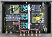
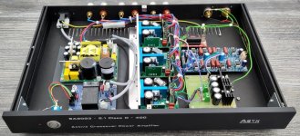
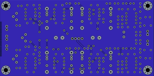
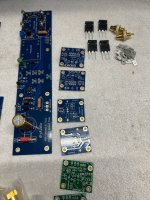
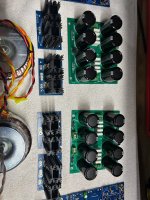
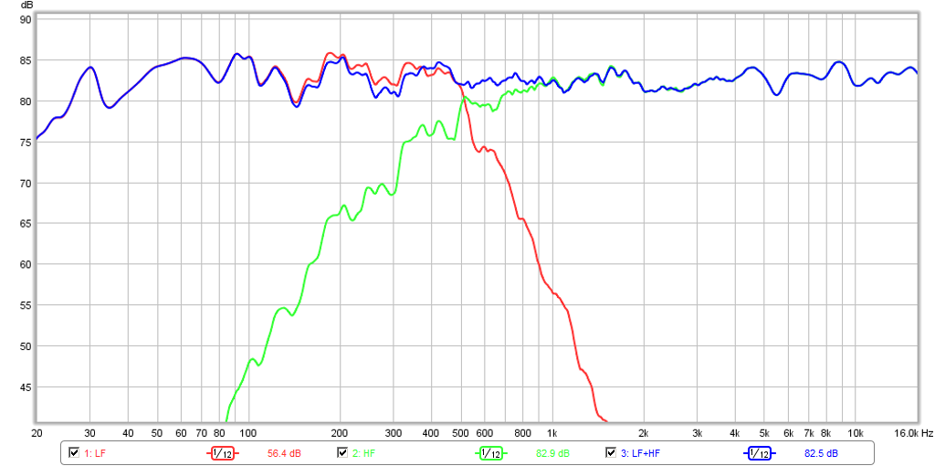
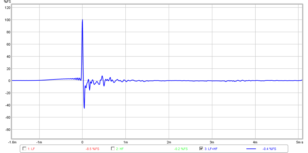
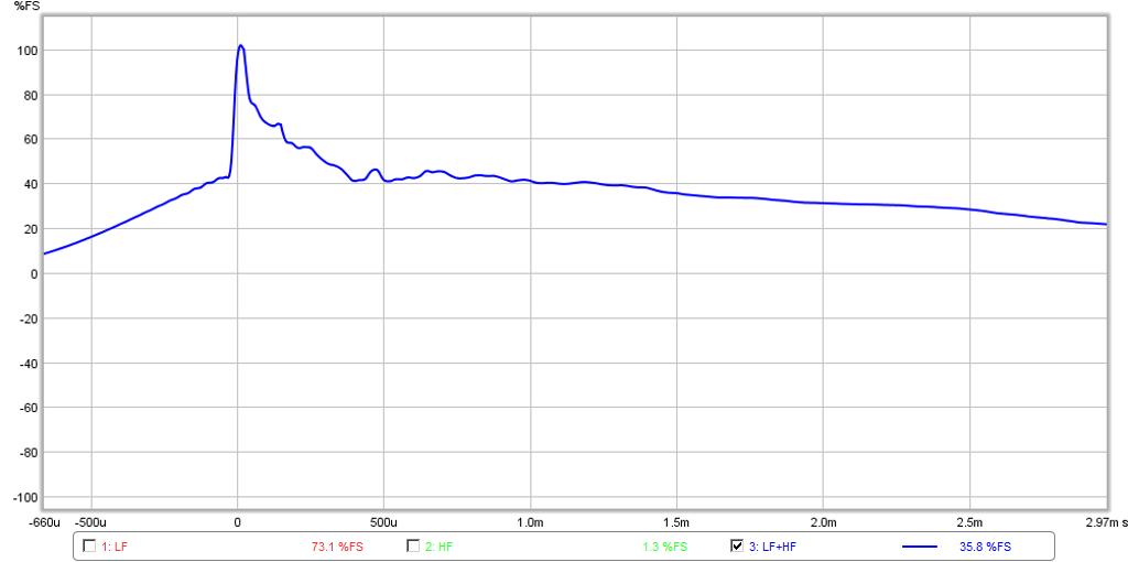
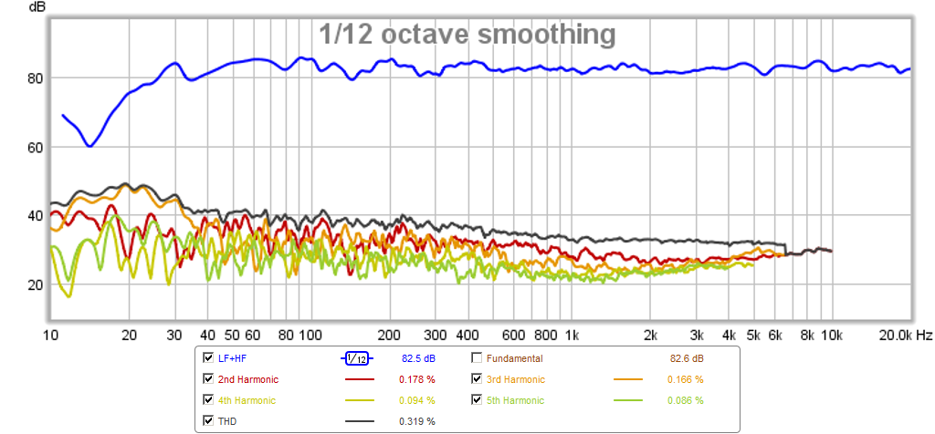
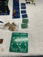
SA2023 2.1 Class D - Active Crossover Power Amplifier using 3 Hypex UCD180 modules

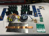
Has been a long time to finish this 2.1 active crossover amplifier project.
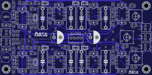
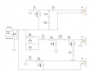
The projects idea started 2017 by designing a 2.1 linkwitz riley 24dB analog crossover pcb.

Hypex components used in this amp:
1 x SMPS400A180
2 x UCD180 HxR
1 x UCD180

Modushop.biz:
1 x Slim Line 01/280 10mm BLACK front panel - 3mm aluminium covers - Rear panel: Without IEC hole. Typ: 1NSLA01280N

Own components used in this amp:
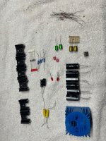
1 x +/-15V powersupply for the analog crossover - +/-21V derived from SMPS400A180
1 x analog crossover pcb
1 x sa2022 grounding pcb
1 x 5V power supply with 230V/16A relay - prepared for MCU control

The crossover frequency is tuned to 80Hz. The 2 basschannels are mixed down to a mono subwoofer signal.
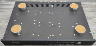
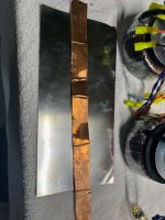
The 1 HE sized case has been diy machined and diy engraved at home using a grblHAL style diy CNC machine.

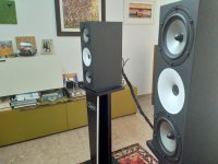
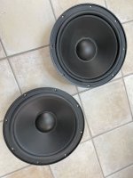
A perfect combination to drive my outdoor 2.1 system (2x Polk audio Atrium 8 SDI and one Atrium SUB100)

Have fun,
Toni

Attachments

  • IMG_20230709_114852.jpg
    IMG_20230709_114852.jpg
    160.7 KB · Views: 238
  • IMG_20230709_114839.jpg
    IMG_20230709_114839.jpg
    196.4 KB · Views: 263
  • IMG_20230709_114509.jpg
    IMG_20230709_114509.jpg
    746.7 KB · Views: 265
  • IMG_20230709_114455.jpg
    IMG_20230709_114455.jpg
    128.2 KB · Views: 266
  • IMG_20230709_114437.jpg
    IMG_20230709_114437.jpg
    82.8 KB · Views: 238
  • IMG_20230709_114428.jpg
    IMG_20230709_114428.jpg
    213.8 KB · Views: 253
  • IMG_20230709_114353.jpg
    IMG_20230709_114353.jpg
    137.8 KB · Views: 235
  • subwoofer_crossover_schematic.pdf
    subwoofer_crossover_schematic.pdf
    38.3 KB · Views: 163
  • subwoofer_crossover_pcb_top.png
    subwoofer_crossover_pcb_top.png
    420.2 KB · Views: 227
  • subwoofer_crossover_pcb_bottom.png
    subwoofer_crossover_pcb_bottom.png
    337 KB · Views: 230

Rockford Prime 1000.1D - identifying smd caps

Hi,
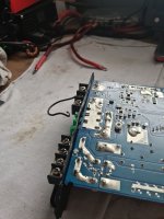
Have this amp for a repair. No class D switching, nothing in short.
Was mounted freely in a trunk, an object hit it really hard looking at the deformed metal heatsink.
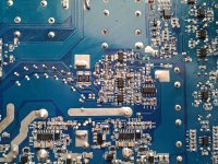
SMD caps C117, C141, C102 were cracked/split in half, maybe I will find more like those while poking around. Does anybody has schematics around the PWM / flip flop ic section or can tell me what are the values for those smd caps in the attached picture ?

Attachments

  • 1.jpg
    1.jpg
    462.6 KB · Views: 86
  • 2.jpg
    2.jpg
    781.7 KB · Views: 86
  • 3.jpg
    3.jpg
    549.3 KB · Views: 84

Measuring enamel thickness and enamel permittivity on winding wire

Does anyone know how one can independently measure the thickness of enamel and/or enamel permittivity of enameled wire?
Of course, if one knows either one of these two qualities, the other can be determined by the salt water immersion test (measure capacitance between the wire and the water.) A large scale transformer manufacturer who buys wire in hundreds of kilometres, the manufacturers would no doubt provide such data. But for me, a one man semi-hobbyist/semi consultant, that won't happen. The IEC published a standard, 60317, but manufacturers of wire readily available seem to ignore it.
One cannot just use a micrometer on the OD because the tolerance on copper diameter is large compared to enamel thickness. I tried various means of removing enamel, such as scrapping, heating with a gas flame then scrapping, but got very inconsistent results. Common solvents such as gasoline, paint stripper, etc have no effect at all on the enamel.
Note: I posted this question a few weeks ago, but the thread was hijacked by people, obviously not involved in inductor/transformer design or making such, seeking to convince me I don't need to know. If I didn't need to know, I would not have asked the question.
In a machine-wound closed packed winding, capacitance is determined by both the enamel and the surrounding air or impregnant. One needs to know both thickness and pemittivity of the enamel because the electric flux is concentrated where the tuns touch - the degree of concentration is dependent on the ratio of these quantities.
some thought there is no mathematical formula one can use to predict self capacitance. But there is - for example Massarini's method, or Koch's method.

Woden Design Linear Quadrupole Designs

Since I've found these intriguing and have not seen any real discussion, I thought it might make sense to start a focused thread on them. Perhaps, they are best not labeled 'Woden Design' as all I've seen are on MarkAudio's site, but it seems appropriate.

Some Initial Questions:

1) Do these result in a similar sound field to that of the MBL RadialStrahler systems and, perhaps others similar (Manger?, Ohm Walsh?)? Without the added complexity of crossovers for omnidirectional considerations.

2) Does the need to site them around four feet from the nearest walls diminish if they are not square to the walls of a rectangular room?

3) There are quadrupole designs for three of the MA 11CM drivers (MAOP11ms, Alpair 11MS, CHN110). Each has different interior dimensions. Could the same dimensions be used for all three with adjustments to the vent length and diameter without any real compromise?

4) If I would like to be able to readily change vent length and diameter without needing to do work inside the cabinet, would using exterior mounted vents without any protrusion into the cabinet work? I'm thinking of round cylinders of wood that would attach to the cabinet with a larger hole in the cabinet, large enough to not alter the vent function.

I'm interested to see the responses and would love to know about any builds.

Skip

Overcurrent protection monitor for a direct bias amp

Does anyone have a schematic, (or sell a PCB), for a circuit that can monitor the voltage drop across a 1 ohm sense resistor and output a latched high output if the voltage goes over the pre determined set point? Whereby if the voltage rises over a set point it will output a latched high that can then be used to energize a relay that cuts mains power via its NC contacts. For example your amplifier loses its bias for some reason, your four 300B tubes worth $1,000 start to melt down and you want the whole amp to simply turn itself off. I see that the INA300 chip does exactly what I need, but I don't want to start from scratch on that.

3 way project - final impedence too low

Hi all
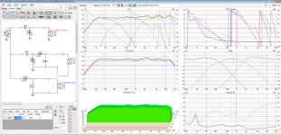
some years ago I built a couple of 2 way speakers based on mid-woofer SB17NRXC35-8 and a tweeter SB26STC-C000-4.
The cabinet was sealed with a volume of 15L
I enjoyed a lot them, but I feel that bass are too poor. So I decided to realize a new project 3 way that is an extension of that one.
I'm evaluating 2 sub-woofer: SB26SFCL38-8 or dayton sd270a-88 (the first one to be preferred bcause it is 8 ohm).

I designed the cabninet, all SPL response and the crossover. My only problem is that the final impedence seems too low (about 2 ohm expecially at high freq) and I'm not able to adjust it. I tried with LPAD, but I'm not so familiar and I was not able to reach good result.

Can someone help me?

Attachments

  • vituixcad.png
    vituixcad.png
    313.7 KB · Views: 208

Open-source USB interface: Audio Widget

Announcement: Audio Widget project

The Audio Widget project is open-source code and schematics for
USB based digital audio. It has functional firmware and software. And
it sounds good!

Cool? You bet! Here you can get started with USB audio without
worrying too much about the USB part of things.

Or you can contribute to a great open-source coding project. The
most important contribution we could need right now is coders for
USB Audio Class 2 drivers on Windows. But other efforts are needed
too. See below.

The code is written in C for the Atmel AT32UC3A3256 32-bit MCU. It
supports USB Audio Class 1.0 and 2.0 (UAC2). On Windows / UAC1 it
works with 24/44.1 and 24/48 with sample skip/insert. Asynchronous
USB is in progress, and we could use your help.

On Linux (>2.6.37) and OS X, using asynchronous USB, it also
supports 24/88.2, 24/96, 24/176.4 and 24/192. The open-source
firmware is in a git repository. It can be selectively compiled to run
on the three different boards. The firmware includes several UI and
display options.

There are three hardware options. The hardware is in a beta state. It
plays music very well, but there is still tweak potential.


1) A stand-alone USB-DAC with stereo audio playback functions only.
This board uses the ES9022 DAC chip. Contact
george.boudreau@YoyodyneConsulting.ca for info on how to obtain
one. More information on the this and other audio designs visit
Yoyodyne Consulting/Audio Hardware

2) USB-I2S module + Analog Board. The module has all the pinouts you
need for digital audio, GPIO, I2C, SPI, LCD display and UART debug.
The module uses 2.0mm pitch pin rows. The Analog Board uses the
module to do stereo playback with an ES9022 DAC and low-noise
VBUS-LDO based power. AB-1 is a straightforward design to begin with,
and if you're into analog tweaking we challenge you to make your own
versions! Schematics and BOM are on
Downloads - sdr-widget - Audio and Control Interface for Amateur Radio SDR and Audiophile USB-DAC - Google Project Hosting.
Go to Q N K T C USB-I2S Module and Analog Board 1 for more information. Contact
borge.strand@gmail.com to obtain a kit.

3) SDR-Widget Beta 2.0. This is the original fork of the project,
open-source HAM radio. The hardware supports both playback and
record. Contact george.boudreau@YoyodyneConsultingl.com for info
on how to obtain one. Visit
Yoyodyne Consulting/SDR-Widget
for more information of pricing and availability.

For more information, go to sdr-widget - Audio and Control Interface for Amateur Radio SDR and Audiophile USB-DAC - Google Project Hosting
and
https://groups.google.com/group/audio-widget?hl=en
This announcement is cross-posted. Please join the mailing lists of
both SDR-Widget and Audio-Widget to continue the discussion there.

SDR-Widget is the original branch, where most of the firmware
discussions take place.

Feel like contributing? We'd always like to see more hands. There's
quite a few tasks planned:

- Firmware for Asynchronous UAC1 / Windows for 44.1 and 48ksps.

- Analog tweaks. Ideas are welcome for PSU, DAC, IVC, preamp etc.
Feel free to make suggestions, or even better, your own Analog
Board for the USB-I2S module.

- Windows open-source drivers for USB Audio Class 2.0. This
protocol is supported in Linux and OS X kernels, but not yet
in Windows.

- Adding more IO control to the firmware


Cheers,
Børge

Jeff Bagbys Universal Crossover Query

Rather than muddy my other speaker post I'll ask for answers here.
If I want to play "Mix&Match" with different boxes as Jeff talked about I'll want to put the XO in a separate enclosure and either use it as a base or as a divider and sit the second box on top.

Would the components get warm enough to need a ventilated box?
I've made standalone crossovers before but I've made those in old amplifier cases so I've never had to think about heat issues

Hello from Korea! Excited to Join DIYAudio 🎶

안녕하세요 여러분.
이 놀라운 커뮤니티에 가입하게 되어 매우 기쁩니다!


저는 하이엔드 오디오 디자인, 특히 DIY 스피커와 크로스오버 네트워크에 깊은 열정을 가지고 있습니다.


최근에 Accuton 드라이버(C25-6-158, C90-6-079, C173-6-191E x2)를 사용하여 4방향 스피커 시스템을 설계하고 맞춤형 패시브 크로스오버를 신중하게 만들었습니다.
AI(ChatGPT)와 철저한 계산을 통해 부드럽고 자연스러운 소리를 위해 주파수 응답과 위상 정렬을 조정했습니다.


이 멋진 취미를 계속 발전시키고 즐기면서 여기 계신 모든 훌륭한 전문가분들께 배우고 제 프로젝트를 공유할 수 있기를 기대합니다.


환영해 주셔서 감사합니다!
제목 없음 - 제외 (2).jpg

DA Ultimax II 18" for Sealed box (first build ever)

Ive had my hsu VTF2 Mk3 forever and I kinda wanted something new. Bringing a whole subwoofer from the US (live in Brazil) checked in on the plane is a huge hassle. I know, cause thats how I brought my hsu sub back home. After online dating with Speedwoofers I've decided that it's easier and better to just buy the driver, amp (not sure if plate or external) and assemble it here in Brazil.

I was thinking. If I get a 150ish liters box (not counting the area of the driver itself, potential amp or braces might take), would that be enough for a good response? I live in an apartment, even my hsu sub never ever reached anywhere near its potential, so I'm really not looking to reach some crazy output. My goal is to have an agile that performs very well for music and can deal with a good range (20hz+) for movies and videogames. 18 inches may sound a bit overkill, but since I can't just swap the driver cause I have to fly to America to get another one, I just don't wanna waste the trip.... does that make sense?

I cant get my hands on 0,25mm MDF here, which is pretty much equivalent to one inch thick. I was thinking maybe using the 1 inch thick MDF would make me require less bracing making the build a lot easier?
Also maybe using a external amp could make my life easier too for the assembly and maybe I could save money with a used external amp... I use a Denon 3313 CI. Do I need anything else? Or is it just the amp, woofer and enclosure?

Any thoughts? The Ultimax II 18" measurements made me really excited!!!
Help me out, and if you think something you might wanna point out is too obvious: don't. I'm stupid, go ahead and say it. I'm just an ******* with a dream here.

Travel speaker build

First, you should know:
I am a seafarer and I spend fully half of my adult life out at sea. I'd like to say it's just a job, but it really does qualify as a life.

Second thing: I built a powered speaker system to suit my job and I'll tell you the things it needed to achieve in order to even make it aboard a ship with me.
  1. Minimum weight: check in luggage has weight limits if you aren't filthy rich. I think the whole setup (2 speakers, MiniDSP Flex & cables) is around 25lbs.
  2. Small box dimensions: keeping things small is actually a good way to keep weight down as well...less wood, less weight...and Small box means small suitcase witch might also weigh less.
  3. Nothing stands proud of the box: it's soo much easier to protect the drive units if the surrounds or domes aren't sticking out into harms way. Just tape a protective piece of cardboard over delicate drivers and done!
  4. Wide bandwidth at the expense of SPL: staterooms aboard ship are tiny so no need to get crazy loud....but I still like bass.
045.jpg
The completed package.

More later.

Russian TV damper diode (6D20P) heater-cathode voltage

Hi,

To make a long story short, I'm working on a SET design with a slightly complex PSU design (200, 270 and 380Vdc from three separate transformer windings).
I plan to use 2x 6AU4GTA in a hybrid bridge for the 380V rail (@140mA) and I also wish to use vacuum diodes for the other two (20mA and 100mA respectively).
To keep the costs down I've been looking at russian dampers (6D14P and 6D20P) for the input and driver tube supply rails but I can't quite figure out how to interpret the heater-cathode insulation ratings in the datasheets:
6d20p.jpg

Would it be safe (in long terms) to use these tubes as rectifiers up to less than 300Vdc with the heaters referenced to ground?
I could connect the heaters to the cathodes but would prefer not to if possible, no other tubes will be powered by the same heater windings though.

PP 6V6 amp from RCA RC-19 manual -- Thoughts?

I'm trying to decide on a push-pull amp to start building. I have most of the parts required, including transformers, and a couple of hand-me-down chassis I can use. I was thumbing through one of my old copies of the RCA Receiving Tubes manuals and found this in RC-19:

1725464422957.png


R18 and R19 (100k) take signal off the 6V6 plates to the 6AU6 driver cathodes for NFB.

R9 and R10 (330k) are a mystery to me. Simulation shows they increase the NFB a little. But how? I guess they feed a little output signal from the cathodes to the grids of the 6AU6s. That would create a little positive feedback, no?

Otherwise the design is straightforward.

I don't have a 9k or 10k OPT, but I do have a pair of 8k:VC OPTs.

The capacitor values introduce high pass filters in a couple of places that result in an infrasonic peak closed loop. I'd increase the values of C3, C4, C7, C8 to smooth that out. Otherwise the design looks well behaved, as the OPT is not within the feedback loop.

I would also improve the power supply; make it stiffer by using UF4007 diodes and bigger reservoir and first smoothing caps, and try to stabilize or regulate the 6V6 screen supply.

QUESTIONS:
  • Would it be better to use plate-grid FB around the 6V6 outputs, or is the 6V6-plate to 6AU6-cathode FB basically the same thing done a little differently?
  • Is the addition of R9 and R10 a good idea? I've never seen that done in any other amp designs I've looked at.
  • I assume using a 6FQ7 or 6CG7 in place of the 12AU7 would be an improvement and would not require much in the way of changes. Good idea?
  • I might also try this with EL84 or even 6P15P outputs instead of 6V6s. Thoughts on that? I think it would be an improvement, and they'd be easier to drive as well.

???

Matching horns to compression drivers, a discussion

A thread to discuss how well a compression driver matches the profile of a particular horn, and how to determine that match - or mismatch.
When choosing a compression driver to go with a particular horn, what is important to know so that the two work well together? Can any driver be used with any horn? Or do some compression drivers work well certain horns and not well with others?

EDIT: April 19, 2023

Attached to this post you will find a spreadsheet, kindly provided by @marco_gea, that allows you to calculate and see the match between a given horn and driver. The spreadsheet takes the parameters of the compression driver throat and calculates an exponential horn that has an equivalent flare rate to the driver throat. With that information you can calculate and see how well a certain expo or hypex horn will match the driver's initial flare rate.
Instructions are included in the spreadsheet.

Obviously the first thing we would look at when choosing a compression driver for a horn is "are they the same size?" In other words, is it a 1", 1.4", 1.4" or 2" entrance to the horn? We normally choose a driver of the exit size as the horn throat. Also to be considered would be the mounting style, such as screw or bolts and the bolt pattern. Adapters can be used for different mount styles and even sizes. For example a common adapter is to use a 1.4" exit driver on a 2" entrance horn. PRV even make a 1" to 2" adapter. But beyond those obvious mechanical matching issues, will a certain driver work well or poorly with a different horn? And how can we determine that for a good match? How do we know the internal geometry of a particular driver?

DE1095TN.jpg
Faital-1inch.jpg
Radian-Altec.jpg


Horns come in many shapes, sizes and profiles. We might look at a Smith horn that has no vertical expansion at all, but a wide horizontal expansion, to a Kilpsch horn with a long narrow vertical expansion and somewhat wide horizontal expansion - to a long horn that looks somewhat like a trumpet, to the Yuichi and others with mixed expansion.
Klipsch.jpg
long-horn.jpg
B-C_horn.jpg


I'll cite a recent example. Forum moderator @kevinkr recently went thru a good deal of trouble and expense to learn what driver works best for his new Yuichi horns. The Yuichi is a wide horn, but not very tall. In fact the horn very quickly goes to over 90° flare in the horizontal axis, while remaining with zero expansion along the vertical axis for about half its length. The horn is very much axi-asymetric, as opposed to a round horn where the expansion is axi-semetric. Is the horn a rapid expansion, narrow, or somewhere in between? What driver geometry would work best on this horn?
This is what the Yuichi looks like inside.

Yuichi-top.png
Yuichi-side.png

Attachments

Who is using a ZEON based machine to render projects.

I recently was glancing at posts and someone mentioned that they had a ZEON based computer with approx 150gig of memory and it was taking several hours to render projects but this was compared to days with a weaker system. I recently was gifted several servers and about a terabyte of ram. Two of the servers can handle 4 cpus. I believe that I can set up a server with 4dies 24cores 48threads and 512gig of memory. The system is absolutely useless for me but it would be interesting to render some of the projects and see how it performs compared to other's systems.

I believe the the model that was being discussed was a wire frame stress model or some such.

At any rate I am requesting some one to tell me what software is needed and offer a project file to be rendered so that we can see the performance.

Jeremy

And now what ..? Anybody has spare Lowther DX3/4 basket cone assembly or planning an upgrade ?

Greed is killing me 🙂 I bought a used pair of DX3 with one reportedly distorting. A common thing with Lowther needing alignment methought . Yeah, right ! There is nothing to be done except $$$ replacement and I will have mismatched drivers anyway.

Attachments

  • 20250427_171216.jpg
    20250427_171216.jpg
    344.3 KB · Views: 49
  • 20250427_171233.jpg
    20250427_171233.jpg
    377.9 KB · Views: 49

Revisiting choke sizing

Hey all,

I'm working on a new amp build - sissysit24 😉 Zen recommended a choke. I have a few questions - hoping to sort things out.

I read up on https://www.diyaudio.com/community/threads/how-do-you-calculate-choke-size-in-a-power-supply.159832/ which covers this topic but is closed so started a new one.

Assuming I did the math right on things:
  1. I think the amp is 25w, need to verify that
  2. I think the current draw, based on the 24v 25w would be approx 1 amp ish. ( per channel )
  3. Based on the formula I think I would need a 2H choke
    1. (24 / .01)/1200 == 2
    2. I'm not sure I'm doing this right!
I'm a little unclear / hazy on where the choke would be placed. If I am understanding things correctly the choke has an in / out. I would place this choke between the dc + of the rectifier and the + in of the power supply board. Is that right?

I'm planning to use the W12 from @rhthatcher . In this configuration I would end up needing a total of 4 chokes - 2 rectifiers per channel. I think each rectifier would be passing .5 amp - is that right? ( each channel would draw aprox 1 a, dividing that evenly I think makes sense?)

When I go to look for a choke from Hammond the size / current I came up with above don't make sense to me. I think I'm either off on my calculations or just don't understand things well enough yet! If my understanding above is correct then something like Hammond 193NP would be a sensible choice?

Thoughts? Am I in the right ballpark here or off? If there is a thread / doc that covers this please let me know. I've googled and searched but not exhaustive. Most of what I found related to using chokes in tube amplifiers.

Vacuum Tube Amplifier Basics Second Edition - EJ Jurich

The most recent edition of my book is available on my website, ejjurich.com. I discontinued using Amazon. The current version of the book is available as a downloadable PDF document/eBook file for $6.00 all of July. After July the price is back up to $12.00.

Summer is usually a slow book sales month. I am trying the July 50% off price to see if it helps sales.

Why PDF?
PDF documents are readable on just about any device. Unlike standard eBook reflowable formats, content remains static. For technical documents, maintaining a static layout is best. Also, in the PDF, many images are color, including project circuit layouts.
A CD version is available only where US postal service is available. The $12.00 price includes media mail postage.

VTAB-Front-Cover-ejunkie.jpg

Alesis M1 MKII simple improvement of bi-amplifier THD by at least -8dB

Hi,
Before I reassembled those powered speakers after repairing one of them, I tried some so simple mod
to improve THD of each amp section.

This can be applied to a lot of amps, when they cheap out a bit on capacitors in the power section…

To prove my point, I ‘ll run a similar mod and video on a Rotel 840 BX II, which doesn’t have the capacitors mentioned on
the schematic ! Increasing many times the original capacitance feeding the power section, is needed to obtain a meaningful
THD improvement 😊, here between -8 dB and almost -20dB on the best of the two power sections…

I cheaped out myself putting only 470uF on some of the two channels, depending on which one it was…the better one or the regular one, to give them a name 😉.
I certainly could have pushed somewhat further than the -80 dB THD figure , I obtained overall, but felt that was ok for these amps 😉!


Login to view embedded media
  • Like
Reactions: Arthur Jackson

Proac Response 1Scrossover diagram needed

Anybody has the original crossover diagram ? Not a DIY/clone version with different woofer , not RS1 and not RS1sc but 1S . Also is Proac version of D2010 with or without ferrofluid ? This was never cleared out with all the cloning mania in the past. I know that the tweeter is not the same becuase I substituted one of the tweeters in Response 2s with standard 2010 and it was different . more efficient and raspy
Years ago I built a clone based on Troels project with optional Hiquphon Owi1 (no ferro) tweeter and original woofer and it sounds like a bucket of rusty nails. Speakers are boxed for several years and it's a waste of a nice tweeter.

Found someones DIY project

I bought these amplifiers from an old man at work.
He brought them in because he heard i love tubes and he wanted to be rid of the heavy turds at 80 something years old...
I offered him $500 for these and the preamp which was also a diy effort.

The workmanship was poor and the amps didn't work. The boards were a rats nest and the builder used 5 different types of green wire.
I bought them for half of what I figured the iron was worth because I knew i could do something with them eventually.
(The preamp has SUTs)

I drew out the schematic and it did not make sense and it also didn't work, so I knew I'd need to overhaul the whole thing in order to make something worthwhile.
Luckily the A-340 dynaco is an extremely easy to use transformer. I could copy the dynaco mk2/3 but I already had 2x small tube sockets.
Instead I went full Williamson.
I am in fact William's son...
I put 6cg7 in the front sockets for va/pi
And driver.
I built a fr4 circuit board with a bias/balance adjustment pot.
I rewired everything using cloth wrapped wire to Retma color codes.
Now they both fire up and bias in and it's time to put signal through them and start fine tuning them.
20250423_084347.jpg
20250422_200010.jpg
20250422_200004.jpg
  • Like
Reactions: arteom and matsurus

Help Tracing lost signal

Hello all,

My Roland Space Echo Re-201 has an issue, and i’m struggling to troubleshoot. When I have an input plugged into the J3 instrument jack, when the SW3 switch is set to ‘Echo’, there is no dry/direct sound outputted. Please can someone help trace where this dry signal goes on the schematic? The echo signal is outputted on this setting, but just not the dry sound. I’ve been trying to trace, but i’m finding the schematic confusing. Ive been inputting a 1k square wave and tracing with a scope from the OP 13 board to the OP 14B board, i will attach.

I have changed all the electrolytics and this hasnt fixed the issue. I suppose it must be simething else, transitor etc. sometimes when i put a loud signal through it, then the direct appears, which makes me think transistor?
Any help or advice is appreciated, Thank you,

Attachments

  • IMG_9698.jpeg
    IMG_9698.jpeg
    465.4 KB · Views: 57
  • IMG_9699.png
    IMG_9699.png
    398.2 KB · Views: 51

K-502 model B with 11BM8 - Seeking Schematic + advice

Hi team,

I have a K502 with a quad of 11BM8 tubes (similar to the thread kcroy created here https://www.diyaudio.com/community/...unsure-what-tubes-to-use.290013/#post-4684440 but the B version of it). Bought from Antique Electronic Supply in 2008

While moving I managed to loose the schematic that was supplied with the kit when I bought it so wondering if somebody has the same kit as myself and has a copy of the schematic to spare.

I have found the schematics of other kits (3 links below) and as I see the differences are minor to negligible but would be great if I could have the original to be able to compare 🙂
The layout is identical, pretty much all caps have identical values, just certain resistors are different I presume for adjust the gain between the different tubes used amongst the different versions (10GV8, 11MS8 and 6005).
Small project behind this amp is:
  • Do some major cleanup + new case
  • Replace the power transformer since now it's 110V and I want to be able to plug it straight into 220V (dual output 11v ac for filaments + I presume somewhere between 165V and 200V for B+ but need to measure)
  • Replace the output transformers
  • Introduce a bias circuit on the tubes
Thanks in advance for any help.

Attachments

  • 20250420_223243.jpg
    20250420_223243.jpg
    659.3 KB · Views: 47
  • 20250416_095951.jpg
    20250416_095951.jpg
    568.8 KB · Views: 46

K81 (2SK81) identification and pinout

Hi. Lately i’m working on an old synth and just for test purposes i’m trying to replace some old transistors. Ordered them from china (they will be with me here in Greece in a couple of months) but i may have a chance to find equivalents locally too.

-The “very” odd ones are the k81 ones. I assume they are similar to 2sk81.
Can’t find any info regarding their pinout in english.
Are they jfet, n channel fet, mosfet, or what?
Some people say that they are close to the j113, with different pinout. What is their type and what is their pinout? Is j113 a correct equivalent, or is there anything other equally mainstream more suitable? Any idea?

-i also look for 2sc2785 equivalents. Similar sources said that bc546 is a good equivalent, with just different pinout. Is this correct? Anything more suitable, equally easy to find?

- And lastly there is a 2sa1175 (as a muting switch i guess). Same sources suggested bc556. Is it ok? Better equivalent that can be found as easily?

Thanks in advance

Hello from AST Conductors, Greece

Hello from an audiophile DIYers team who also happen to be metallurgists and have put a lot of energy and resources to produce the purest possible silver conductors for audio. We do not want to breach any forum rules, we just hope to inform the members (and we have some members here in our team) of our presence and answer any questions they may have.

LEAP 4 lives!

Are you old enough to remember LEAP 4? only the best loudspeaker design program ever written IMHO.

If so and you want to bring back the good old days of DOS, you can now run it on your window machine, cracked and ready to go. Please see my post in the general loudspeaker forum for details and BTW, someone just posted a LEAP 5 crack .... Good times and thank you Chris Strham, you were brilliant and I cherish our many conversations.

Vituix and DSP - Converting my 2-way to 3

Hi everyone,

If you recall, I'm a big fan of XSim, but I'm embarking on converting a 2-way (AMT tweeter + 6.5" mid-woofer, ported) to a 3 way with the addition of a bass cabinet and 3-way plate amplifier. I took my original FRD measurements for the tweeter and mid, and have spliced in the Dayton reference data for the woofer. None of the levels or delays are probably accurate, they are just here to see how far I can get in this design while I consider whether or not to proceed.

Based on my good luck with LR4 in my center channel I'm trying to use that slope again here. Ignore the phase plots, this is VirtuixCAD under Wine/Linux so the graphics are not 100%.

Thoughts?


1740260189399.png

I have Wadia 16 and Krell Schematics

Over the last week or so I have been working on my 1995 Wadia 16 CD player that stopped working back in 2007 and has been languishing up in my attic for more than 7 years. It worked fine for 12 years then suddenly crapped out. I opened it up back then and poked around, but without the prospect for obtaining any kind of dealer or factory support (Wadia was in and out of being a viable company for years), I quickly abandoned my effort. I remember being really pi$$ed off that a $7000 CD player was essentially junk because some tweaky high end "company" knew how to design, but wasn't so interested in the business aspects of running a company; a hobby run amok. If it hadn't weighed 45 lbs. and was in outwardly mint condition, I might have thrown it out in the trash along with a case of Budweiser to ease the pain of the garbageman.

To make a long story short, the 16 is back up and running perfectly. There were a couple of minor issues including a dirty laser, but nothing that was a show stopper. Troubleshooting analog is one thing, but with the advent of microprocessors and FPGA's, modern electronic equipment is becoming more and more non-user serviceable. Thankfully all of this was in good shape, along with the transport, even after 7 years of zero to 100+ degrees F and wide humidity swings.

I think a lot can be said of Wadia's attention to detail when compares the Teac VRDS servo PCB to the Wadia PCB. The Teac isn't even close.

In the end, the last thing that needed to be done was re-solder the servo board digital output shielded cable that runs to the Wadia digital IO board. I broke it loose at the servo board end when I unwisely attemped to remove the bottom chassis plate which has the servo board mounted to it. You get to the servo board from the top. Since I had no idea where it was soldered to I figured I'd email Wadia last Friday and ask them if they had schematics and assembly drawings for the 16. Based on what I've read here in the DYI forums and elsewhere, I wasn't expecting even a reply from them, but it took little effort to at least try.

Wouldn't you know it, they not only replied, but sent me PDF's of all the schematics and drawings they had on the 16! Now that's customer service!

A while ago, I got similar results from Krell, so I also have complete schematics on the KRC preamp and the MDA 500 amps if anyone needs them.

Regards,
Doug

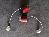
Tube adapters

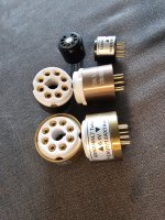
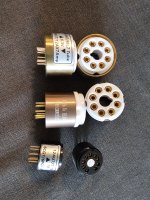
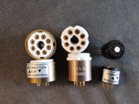
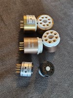
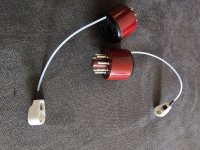
For sale 4 pairs tube adapters.Like new used verry short time and verry good quality.Buyed by Banzai music Germany and Tube Town Germany.
Price for all 8 is 120 euro or best offer plus 7,90 euro tracekd shipping inside EU!The last pair adapters are for 6sn7 to 6f8g!More info on contact.

Attachments

  • 20241019_124338.jpg
    20241019_124338.jpg
    1 MB · Views: 170
  • 20241019_124333.jpg
    20241019_124333.jpg
    1.2 MB · Views: 179
  • 20241019_124353.jpg
    20241019_124353.jpg
    1.2 MB · Views: 149
  • 20241019_124346.jpg
    20241019_124346.jpg
    636.8 KB · Views: 155
  • 20241019_124342.jpg
    20241019_124342.jpg
    918.2 KB · Views: 153
  • 20241019_134505.jpg
    20241019_134505.jpg
    1.4 MB · Views: 137
  • 20241019_134502.jpg
    20241019_134502.jpg
    1.5 MB · Views: 171

For Sale Tube amp transformer

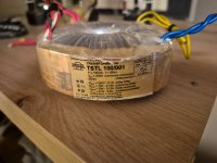
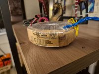
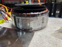
Verry good tube amp transformer for sale.Zransformer with copper shild and specifications that you can see on picture.Price 100 euro including shipping to EU with tracking and insurance.Payment by Paypal.More info or offers on contact.

Attachments

  • 20250309_191244.jpg
    20250309_191244.jpg
    488.4 KB · Views: 161
  • 20250309_191248.jpg
    20250309_191248.jpg
    508.5 KB · Views: 158
  • 20250309_191301.jpg
    20250309_191301.jpg
    478.3 KB · Views: 156

How to use Ferrite Bead in place of Inductors for TPA3118

I didn't find a lot of information out there on this topic. How can I switch out a 30uH inductor for a ferrite bead? I did a little searching and it looks like the low pass capacitor going to ground becomes quite a lot smaller (instead of around 1uF after an inductor, with the ferrite bead that value becomes 0.001uF). But is that all? Are there any other considerations (for it to function)? I did see in the datasheet that layout runs must be compact to the chip. I also saw that it must be able to carry enough current and must go to around 120 ohms at 100MHz.

SylphAudio New DIY Modules

Welcome to SylphAudio thread!

Our New Product Release Roadmap for 2024

1702024090077.png


****

SE800 PFFB High Power Class-D Amplifier
Supply Voltage: dual ± 25V min, ± 85V DC max
Unclipped Power (<1% THD+N, ± 85V): 350W-8Ω, 700W-4Ω
Input configuration: Single Ended
Output configuration: Single Ended
Input sensitivity (PFFB): 2.6V RMS
Voltage gain (PFFB): ~25dB
PCB area: 140mm x 70mm
Overvoltage Protect: ±88V to ±91V DC
Undervoltage Protect: none, UVLO @ ±12V DC
Speaker Protect: none, requires external SP

Can be used with a 2Ω load if powered with a lower power supply voltage around ± 60V DC, can reach 800W output (< 10s burst signal).
Designed with PFFB to reduce load dependency and improve noise and distortion. 5W at 4Ω THD+N is around -82dB, with THD at -94dB.
Rugged and super-stable PFFB design based on TI, implementation by SylphAudio.

ETA: Jan 2024

Sample pictures
1702022880237.png

1702023249531.png


FB100 and FB360
We've applied the largest feedback factor possible without reducing the output power capability. Which results to exceptional performance.

FBUltra
Under development, composite OPA1612 and LM3886 design.

Pass "DeLite" Amp from BAF

EDITORS NOTE: This is the single depletion mode Mosfet amp that Nelson Pass demonstrated at Burning Amp this year. END


I just opened an unexpected arrival from Jon this morning....

After seeing this, who can resist?

(Tea-bag, thanks for the photo)

It's worth noting that I am considering some other tweaks
on this as well.😎

J-fet CCS? 😎🙂

Attachments

  • ba09_ 021.jpg
    ba09_ 021.jpg
    112.4 KB · Views: 10,285

For Sale 50% of Whammy Headphone amp parts

I have some spare parts if someone has a whammy board and they need a good deal on some parts to get them going. This has MOST of what you need to get the power supply completed.

What is included:
- brand new Talema 18VACx2 25VA transformer

- all the heat sinks (low profile)

- 6 Panasonic 3300uf 35V caps

- 4 IN4004 diodes

- 4 5.1 ohm resistors (for the CRC psu)

- red LEDs

- 2 pairs of different 220uf caps

- a pair of Nichicon UEH bipolar 22uf caps

- opa2134 opamp

- a pair of 1uf poly caps

- assortment of Vishay/Dale RN55 1/8th watt resistors.

I am asking $60 shipped and will throw in some Mogami wire.

Attachments

  • IMG_6546.jpeg
    IMG_6546.jpeg
    1.2 MB · Views: 55
  • IMG_6547.jpeg
    IMG_6547.jpeg
    804 KB · Views: 56
  • IMG_6548.jpeg
    IMG_6548.jpeg
    833 KB · Views: 53
  • IMG_6549.jpeg
    IMG_6549.jpeg
    850.8 KB · Views: 48
  • IMG_6550.jpeg
    IMG_6550.jpeg
    870.8 KB · Views: 55

For Sale Parts for Dual Mono M2x Amplifier and other goodies (Includes Edcor Transformers)

Unfortunate work circumstances force me to sell of some DIY parts. I am selling the whole setup below for $325 shipped Conus. I did a rough estimate and sourcing these parts brand new would put you around $450. Keep in mind I only have the 3 pairs of daughter boards.

Here is everything you get. Keep in mind some parts have been used, some brand new, and the m2x boards untested.
  • Two Triad VPT36-4440 (2x18VAC 160VA) Transformers (USED)
  • Four diode bridges using MBR20200CT (USED)
  • Two Power supply boards with 60,000uf per rail and CL-60 installed for GLB (USED)
  • Two M2x boards with 6l6's DC offset modifications (NOT TESTED)
    • Edcors installed with Copper Strips
  • Three Daughterboards - Norwood, Ishikawa, and Cedarburg (BLANK)
  • Set of Gold Plated Binding Posts (NEVER USED)
  • Unmatched set of IRFP240/IRFP9240 Mosfets (NEVER USED)
  • Pair of Gold Plated RCAS (NEVER USED)
  • XRK's Daughterboard testing PCB (NEVER USED)
  • Mu Metal to cover the Edcor Transformers (to shield the Edcors)
  • Spade connectors for the M2x boards and the diode bridges

Some of these parts will show wear from storage or use, but I can guarantee the diodes and PSU's work perfectly. I replaced all of these parts with SLB boards which is why I no longer need them.

Attachments

  • IMG_6588.JPG
    IMG_6588.JPG
    703.7 KB · Views: 138
  • IMG_6593.JPG
    IMG_6593.JPG
    630.1 KB · Views: 142
  • IMG_6589.JPG
    IMG_6589.JPG
    734.7 KB · Views: 128
  • IMG_6592.JPG
    IMG_6592.JPG
    690.8 KB · Views: 125
  • IMG_6595.JPG
    IMG_6595.JPG
    396 KB · Views: 123
  • IMG_6591.JPG
    IMG_6591.JPG
    583.9 KB · Views: 141
  • Like
Reactions: STOXX and birdbox

A Bargain Basement Idea for Budget Installations?

Every year I use dumpster parts to make a garden system for the summer. I live in a block of 5 apartment with a communal garden & a bunch of neighbours who love to barbecue! The system only has to last the summer. I don't care if it gets broken & abused.
The first 2 years I made 2.1 systems using D3116D2 chip amps using a laptop PSU - they worked well.
Last year I went in a different direction . . .
DVD / Blueray Receivers have one moving part that is guaranteed to fail. When that part fails they are worthless. You can pick them for $5 - $20.
What remains is a remote control USB player (possibly with Bluetooth) & 5 or 6 amplifiers and an active crossover in a single box,
I picked up an LG HT902PB - 1000 watts (yeah, right). The garden sounded great: a 10" sub & four bookshelf speakers.

In helping my small business friends out, I have installed faulty DVD receivers in two local restaurants & two hairdressers.
These units have untold hidden benefits, not least the ability to control the volume and delay of individual speakers is something you are unlikely to get on even high-end commercial systems.

The tolerance is also impressive. The subwoofer channel claims to deliver 255 watts into 3 ohms, so I guess there'd be few problems running two subs off the one channel.

Transformer winding material, where to buy?

Where to buy transformer laminations, magnet wire and bobbins, preferably in Europe?
And . . . whatever happened to delatsch.com ?
Delatsch sells transformer winding spreadsheets and used to sell all the materials needed, like laminations, magnet wire etc.
but now materials are removed from the web shop.
Little use then by buying the spreadsheets if the needed materials are not available for sale.

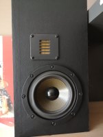
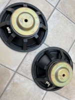
For Sale Four NHT1259 drivers

I have 4 NHT1259 drivers for sale. I purchased these from Madisound back over 25 years ago, for an isobarik subwoofer project. They were (and still are) highly regarded drivers. They have about 100 hours of use, as they have been in storage for the past 20 years. I no longer have the space to store them.

They weigh over 4 Kg each, so shipping costs will be significant, so a local pickup (south-west France) would be ideal.

I will consider any reasonable offer.

note: photos only show 2, however the other two are in identical condition.

Attachments

  • NHT-1.jpg
    NHT-1.jpg
    311.1 KB · Views: 204
  • NHT-2.jpg
    NHT-2.jpg
    338.1 KB · Views: 203
  • nht1259.pdf
    nht1259.pdf
    209.4 KB · Views: 140
  • Like
Reactions: Arez and taloyd

Intro 🤪

Hey all! :king: :hbeat: I'm a professional studio vocalist & vocal producer/songwriter, and have gotten into effects pedal building in the past few years. Being a singer, my most recent and most ambitious project is a diy mic preamp, which I am excited to build from scratch (pcb design, enclosure design, building etc.)
Always been a music nerd, and (audio) technology fascinates and inspires me. Looking forward to learning & growing together! 🤩🤓

Bridge Rectifier Help

Hello,

New to this forum!
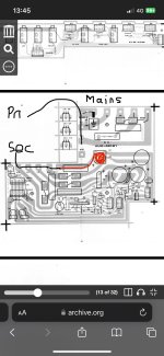
I’ve been trying to fix my Poly 61- the transfomer gets hot when switched on (i heard a bang near the power supply side one time when i was fitting a Midi kit) i have descovered this only happens when under load when other boards are connected, and the bridge rectifier gets very hot, so i’m convinced its this that is at fault. After connecting another board to the supply and taking chips off to lower the current load, the transformer cools and the bridge rectifier still gets very hot. I could’nt find any shorts on the other boards.
In the schematic, you can see this part is connected on the secondry side, and is labelled D3. I will attach.

Please can someone advise me which replacement bridge rectifier part to get? I’m unsure what the numbers mean, and the schematic power supply page is unreadable, it just states the part as 4B4B41?
I’m not sure how to test these components also, and if it is at fault, then it might be tricky to buy another seen as this one is at fault? Will a generic bridge rect diode part work as a replacement? I’m cautious of buying another part and using as it could cause more faults (and obviously dangerous), i’ve spent so much time trying to get to the bottom of this and I can see light (maybe) any help here to advise would be appreciated, thank you


Kind regards
Connor

Attachments

  • IMG_9694.jpeg
    IMG_9694.jpeg
    325.2 KB · Views: 79
  • IMG_9693.png
    IMG_9693.png
    3 MB · Views: 80

For Sale Lot of caps for half price

SOLD -thanks for looking

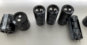
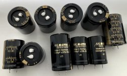
For those interested, here's an opportunity to save a lot of money. I'd like to get rid of some capacitors that I have left over from various projects.

Mundorf MLytic 10.000 uF / 35V 2 pcs.
Mundorf MLytic 15.000 uF / 50V 1 pc.
Nichicon Gold Tune 10.000 uF / 50V 5 pcs.
Nichcon Gold Tune 4.700 uF / 50V 2 pcs.
Panasonic EEUFS1C512L 5.600 uF / 16V 20 pcs.
Panasonic TSHA 4.700 uF / 35V 2 pcs.
Panasonic EEUFR1H221B 220 uF / 50V 20 pcs.
Kemet LH 4.700 uF / 63V 3 pcs.
Panasonic TSHA 5.600 uF / 50V 4 pcs.
Panasonic EEUFR1V222L 2.200 uF / 35 V 6 pcs.
Panasonic EEUFM1V182 1.800 uF /35 V 6 pcs.
Yageo A750KK477M1AAAE016 470 uF / 10V 6 pcs.
Panasonic 16SEPG270W 270 uF / 16V 6 pcs.
Panasonic 16SEPF150M+TSS 150 uF / 16V 6 pcs.
Panasonic PLG0G182MDO1 1.800 uF / 4V 20 pcs.

New completely 254,9 Euro -so now I ask for the half: 125 Euros plus shipping.

The expected shipping costs can be viewed here (select parcel up to 2 kg including tracking): dhl.de

Due to the current customs chaos, I would only sell them outside of Europe subject to checking the effort involved.

The capacitors are new, guaranteed to be genuine, not from Ali or eBay (or similar). They are stored under good conditions, in a well-tempered, smoke- and pet-free environment.

The buyer receives some additional capacitors for free.

Attachments

  • Elko4.JPG
    Elko4.JPG
    119.6 KB · Views: 63
  • Elko3.JPG
    Elko3.JPG
    69.9 KB · Views: 46
  • Elko1.JPG
    Elko1.JPG
    96.8 KB · Views: 45
  • Elko2.JPG
    Elko2.JPG
    107 KB · Views: 49
  • Elko5.JPG
    Elko5.JPG
    85.3 KB · Views: 42

Pioneer PL-5 Speed Issues

I recently bought a Pioneer PL-5. I got it hooked up and found that it didn't play speeds properly. I found a couple YouTube videos that addressed this problem. I took the turntable apart. Cleaned it, oiled the motor bearing, cleaned all the switches and pots with contact cleaner so and so forth.

I put everything back together and tried it out. I was able to adjust the 33rpm with the adjustment pot, but I couldn't get the 45prm to adjust at all and runs too slow. The speeds will would skip fast for a second and the back to normal and there is an audible noise as well when it happens.

I have a feeling that I will need to recap the circuit board, But I wanted to see if anyone else had any other ideas before I start doing that. Is it even worth the trouble recapping it? This isn't my only turntable and fortunately I didn't pay much for it.

Any input would be great!

Thanks

Need Crossover advice, AR 8B (Teledyne) bookshelf speakers

Hello All, I recently was gifted AR 8B bookshelf speakers. Of course the foam surrounds are dry rotted and I have the kit to refoam the woofers.
While I am doing that I got inspired to tweak the crossover thinking that i can improve the sound over the original. The woofer is running free-range with no LP filter. The tweeter uses a 5.0 uF capacitor only. Per what I posted below, it sounds like this was done as a cost-cutting effort and not necessarily to deliver the best sound. I'm thinking a 12 db per octave LP crossover at 2000 Hz is a good idea to prevent distortion. According to AR, the tweeter has an "effective" rolloff of 18 db at 2000 Hz using the single 5.0 uF cap. Should a more sophisticated HP filter be used incorporating an induction coil and a cap, and should the HP filter use a 12 db/octave slope as the tweeter was designed to have a natural rolloff giving an effective 18 db/octave slope? Or should the HP filter use a 3rd order filter? Please advise, the more I look into this the more I am getting confused! Thanks!

"The two-way AR8B is the smallest and least expensive speaker system in the current Acoustic Research line. Like all AR speakers, it is an acoustic-suspension model, and it has a newly designed 6-inch woofer that crosses over at 2,000 Hz to a 1-1/4-inch “liquid cooled” cone tweeter. (The tweeter presumably uses ferrofluid or a similar material to damp and cool its voice coil.) The crossover network has been simplified and its cost reduced by designing each driver to have a natural rolloff outside its operating frequency range. As a result, only a capacitor is needed to protect the tweeter against damage from powerful low-frequency signals. The effective crossover slopes are 12 dB per octave for the woofer and 18 dB per octave for the tweeter."

6S41S Single-Ended Cathode Follower Amplifier

I thought that I should share my recent amplifier build:

DSC_0016_zpsl4soctwf.jpg


DSC_0015_zpsxaoablla.jpg


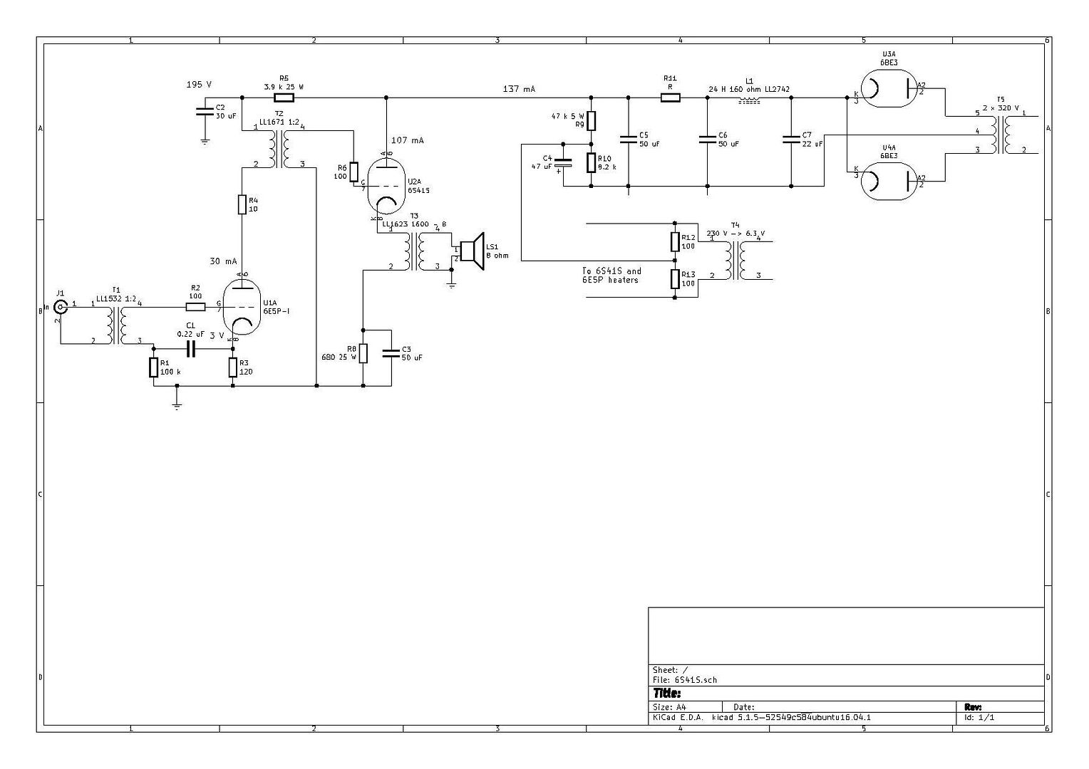
Single-ended 6S41S cathode follower amplifiers that deliver 7 W each. Here is the schematic:

schema_zps1pvsxtw7.jpg


Running the output tube as cathode follower gives a very low output impedance for a single-ended amplifier. These amplifiers can drive difficult loads, but the concept has its cons. The output tubes need over 500 V peak to peak to deliver full output. The driver tube 6E5P-I is a small power tube with high amplification when connected in triode mode. It has a gain around 50 and can deliver quite a bit of current. By using an interstage transformer, I can get the required voltage swing without a very high supply voltage. Also, I step up the signal 1:2 with the interstage transformer and I also step up the signal with 1:2 with the input transformer.

The sound quality is great. It is most certainly the best-sounding amplifier that I have tried with my current speakers.

Lost my way a bit

A couple of years back I scored a decent pair of the old RadioShack Optimus 8B speakers for $50- with some other stuff tossed in for free
Somebody over at AudioKarma was desperate for a set of the mid range and tweeters so I took them out and flipped them [ at a reasonable profit] and the boxes with that great woofer have been sitting in the shed for a long time and I have no idea what to do with them now.
The boxes are in excellent condition although missing the original grill, which I suppose is why they were only $50-
I'm at a loss as to how to proceed so I'd appreciate some thoughts and inspiration from the collective minds of the forum members. I haven't actually finished anything since I made that huge 18" part sub and I am feeling frustrated
Edit
Nova 8B

Greetings

I'm looking to build an Aleph Mini, currently trying to gather parts to order, for now I have found:

https://www.ebay.co.uk/itm/266392011176?mkevt=1&mkcid=1&mkrid=710-53481-19255-0 - the pcb
https://www.ebay.com/itm/156560013829 - mosfets
alternatively, but I'm not sure if it'd be quite right - https://www.ebay.com/itm/115126018088?mkcid=16&mkevt=1&mkrid=711-127632-2357-0&ssspo=wGG0QMocRHa

https://a.aliexpress.com/_EIU0SPC - enclosure

I'm just not quite sure about the PSU, what board / transformer should I use, and how to wire the potentiometer, switch.

10F/8424 & RS225-8 FAST / WAW Ref Monitor

Some sound clips of this speaker recorded with my phone and powered by my SuSyLu 100w Class A amp:

Test of SuSyLu 100W Class A Amp - YouTube

Example of speaker in dark “espresso brown” stain and satin lacquer with Duratex coated baffle.
802945d1576612905-10f-rs225-fast-speaker-xo-pcb-gb-10f-rs225-speaker-system-photo-jpg


Example of beautiful build by as8912:
989264d1633830891-10f-8424-rs225-8-fast-waw-ref-monitor-speaker_4-jpg


Another Example of a floor standing FAST TL by Plott:
1000718d1638010198-10f-8424-rs225-8-fast-waw-ref-monitor-psx_20211127_113955-jpg

This is a great shot of the internals as provided by Plott:
psx_20211124_202322-jpg.1284323


Example of a floor standing TL version of this speaker by Moutik:
975793d1629314524-10f-8424-rs225-8-fast-waw-ref-monitor-497cdaea-6041-443e-b8af-7a10922cfc5c-jpeg


Example of a smaller sealed version with PS95-8 full range drivers by Jimk04, here.

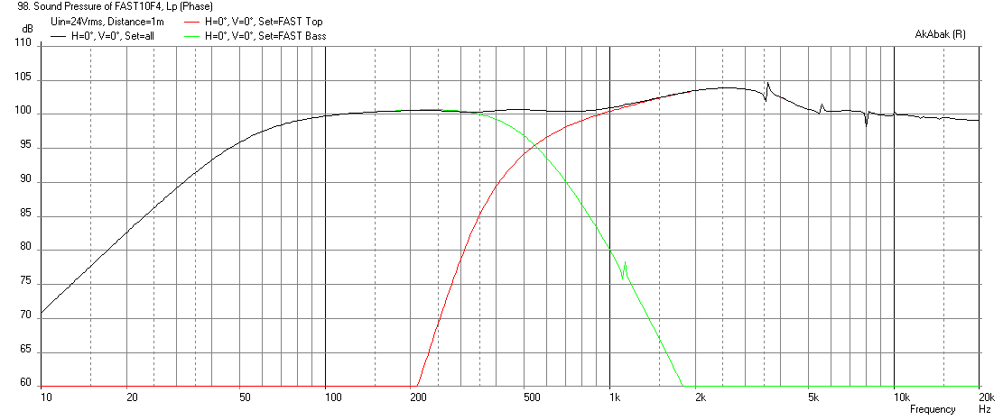
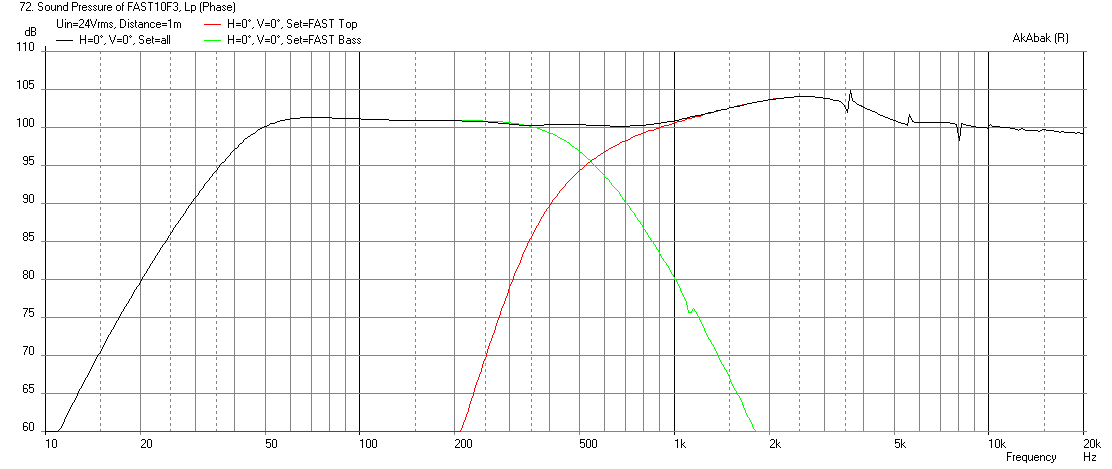
I wanted a speaker design worthy of the exceptionally high performing ScanSpeak 10F/8424 Discovery 3.5in full range driver. I decided that a short sealed Dagger TL coupled with a sealed bass unit would give me the best overall transient response and clarity. I decided to mate the 10F/8424 with the superb Dayton RS225-8 aluminum cone woofer for bass duties. The design ended up as a 24 liter volume for the woofer and a 1.1 liter 3-sided pyramid Dagger for the 10F/8424. The important external dimensions are: 10.0in wide baffle, 7.5in CTC distance from woofer to fullrange, and 24 liter internal volume (sealed). You can make the height and depth to suit your individual case, but it will need to be deep enough to house the Dagger. The internal dimensions I settled on were 8in wide x 12in deep x 16in tall.

However, if you make it out of 18mm plywood like the ones I had my cabinet maker build - make the box using these dimensions.

Dimensions of sealed box version: most important is to make the width 10.0in (external) and CTC spacing between drivers 7.5in and adjust the depth and height so that you have about 24 liters volume. If you make it out of 18mm plywood it ends up about 18in H x 13.5in D. The 10F is located 4.5in top to center. You will need a rear chamber for tweeter (fullrange) so use a sports cone or wooded “Dagger” tall 4 to 5 sided pyramid. Stuff Dagger and main box with polyfill or fiberglass to taste.

New SketchUp Plans by @jrKC for sealed version here.

1713273330665.jpeg


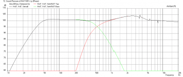
The short sealed TL is made of three 6in wide x 12.5in long triangles. Construction will use 1in thick pink XPS foam and regular foam core for the short TL. The front baffle will also use a thin sub-floor plywood in order to provide adequate support for the heavy 8in driver. The design will have the option of a bass reflex vent that can be sealed for use with a Linkwitz transform, or opened up for some additional bass when group delay is not an issue. The system will use miniDSP for XO and EQ duties and bi-amped. Here are predicted results in 4pi space with baffle step and diffraction effects accounted for. XO will be at 500Hz with 4th order LR. The RS225-8 is an exceptionally flat response driver and choosing a slightly higher XO frequency will keep the distortion on the 10F very low while giving more weight to the mid bass as it comes from an 8in woofer. Calculations show that with Linkwitz transform, bass extension should be about 42Hz (f3) with max SPL around 101dB.

SPL vs freq for sealed case at 24v (no Linkwitz transform) - the hump at 2.5kHz is the baffle diffraction:

479643d1430055264-10f-8424-rs225-8-fast-ref-monitor-10f8424-rs225-fast-freq-1m-sealed.png


Impulse response for sealed case:

479644d1430055264-10f-8424-rs225-8-fast-ref-monitor-10f8424-rs225-fast-impulse-sealed.png


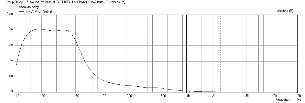
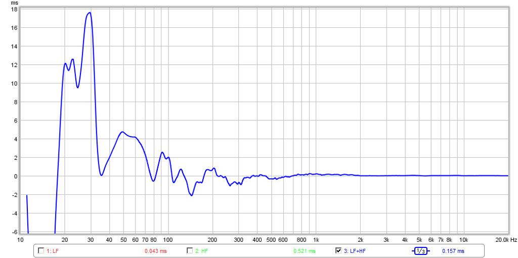
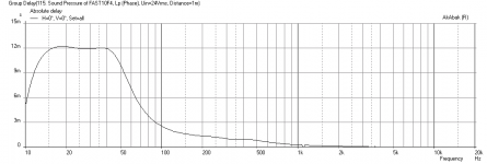
Group delay for sealed case is 2.5ms at 100Hz and 5ms at 50Hz:

479645d1430055264-10f-8424-rs225-8-fast-ref-monitor-10f8424-rs225-fast-group-delay-sealed.png


For bass reflex option, here is SPL vs freq at 24v:

479646d1430055264-10f-8424-rs225-8-fast-ref-monitor-10f8424-rs225-fast-freq-1m-br-xmax.png


Here is group delay for bass reflex (2.5in dia x 11in long vent - rear firing) case, not too bad actually (about 10ms at 50Hz)

479647d1430055264-10f-8424-rs225-8-fast-ref-monitor-10f8424-rs225-fast-group-delay-br.png


Here is the Sureply thin baffle with driver holes and drivers to show basic look:

479648d1430055264-10f-8424-rs225-8-fast-ref-monitor-10f8424-rs225-fast-baffle.jpg


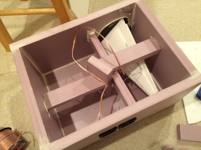
Here is construction on XPS enclosure beginning:

479649d1430055457-10f-8424-rs225-8-fast-ref-monitor-10f8424-rs225-fast-box-baffle.png


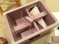
Here is the enclosure with Dagger TL internally mounted and bracing, wiring, and terminal cups installed:

479650d1430055468-10f-8424-rs225-8-fast-ref-monitor-10f8424-rs225-fast-bracing-tl.png


Currently waiting for liquid nails glue to dry...

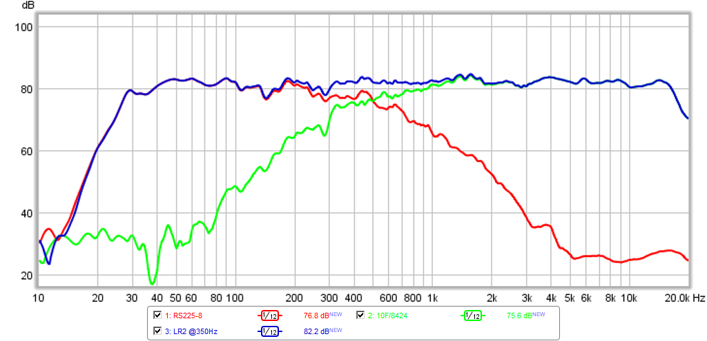
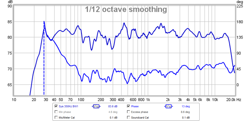
Edit April 27, 2015: New LR2 XO @350Hz and new sound clips of many different genres. Have a listen, this speaker sounds fantastic!

10F/8424 & RS225-8 FAST Ref Monitor - Page 2 - diyAudio

Here is the new LR2 XO @350Hz:
479800d1430134934-10f-8424-rs225-8-fast-ref-monitor-10f-rs225-fast-lr2-350hz-xo.png


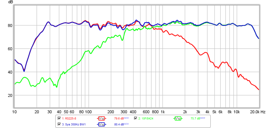
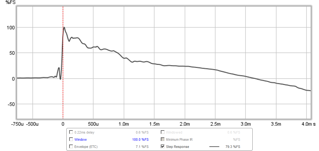
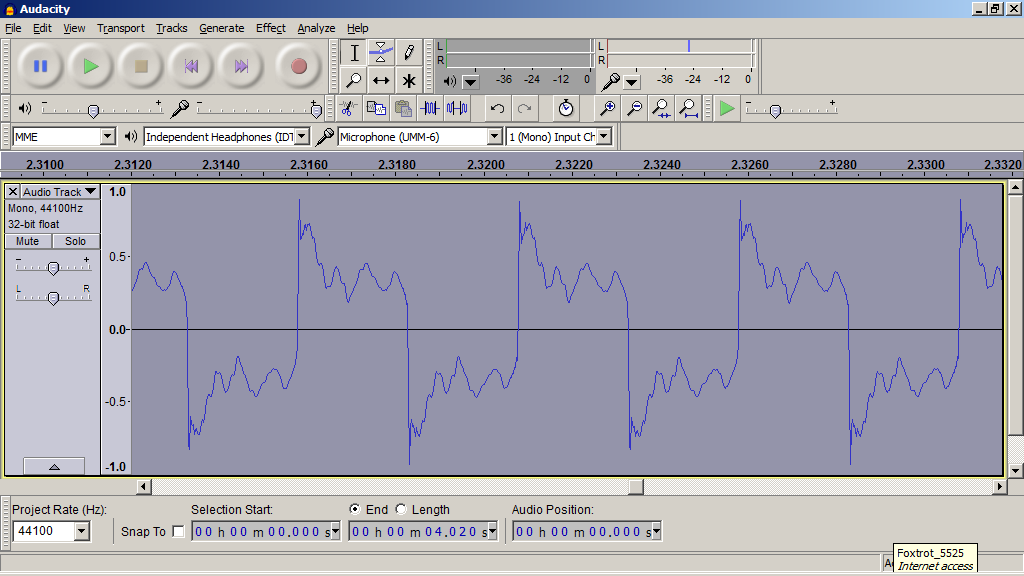
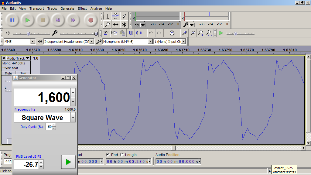
Update April 30, 2015: New Butterworth 1st order linear phase XO (BW1 XO):
480322d1430370786-10f-8424-rs225-8-fast-ref-monitor-10f-8424-rs225-8-fast-bw1-350hz-xo.png


Phase for BW1 XO:
480327d1430370786-10f-8424-rs225-8-fast-ref-monitor-10f-8424-rs225-8-fast-bw1-350hz-phsae.png


Step Response for BW1 XO:
480328d1430371582-10f-8424-rs225-8-fast-ref-monitor-10f-8424-rs225-8-fast-bw1-350hz-step-0.22ms.png


200Hz Square Wave with BW1 XO:

480540d1430448087-10f-8424-rs225-8-fast-ref-monitor-sqwv-200hz.png


1.6kHz Square Wave with BW1 XO:

480543d1430448087-10f-8424-rs225-8-fast-ref-monitor-sqwv-1600hz.png


New sound clip with 1st order BW1 XO: http://www.diyaudio.com/forums/atta...or-10f-8424-rs225-8-fast-bw1-350hz-clip-b.asc

Edit May 14, 2015: Stereo Pair completed!

482977d1431581904-10f-8424-rs225-8-fast-ref-monitor-10f-rs225-fast-stereo-photo.jpg


Edit Dec 16, 2015: forgot to post final lock-down configuration with Harsch XO:
495043d1437630819-10f-8424-rs225-8-fast-ref-monitor-harsch-10f-rs225-xo.png


IR:
495045d1437630819-10f-8424-rs225-8-fast-ref-monitor-harsch-10f-rs225-ir.png


Step response:
495046d1437630819-10f-8424-rs225-8-fast-ref-monitor-harsch-10f-rs225-sr.png

More info on final setup here: 10F/8424 & RS225-8 FAST Ref Monitor

Distortion:
495051d1437631905-10f-8424-rs225-8-fast-ref-monitor-harsch-10f-rs225-hd.png


Group delay about 5ms at 50Hz:
495047d1437630819-10f-8424-rs225-8-fast-ref-monitor-harsch-10f-rs225-gd.png


Edit Jan 5, 2018: using passive 1st order transient perfect XO for past 2 years.
654804d1515144021-10f-8424-rs225-8-fast-ref-monitor-10f-rs225-1st-xo-v2b-jpg


Recent implementation with film caps and air core:
654791d1515138232-10f-8424-rs225-8-fast-ref-monitor-passive-xo-completed-jpg


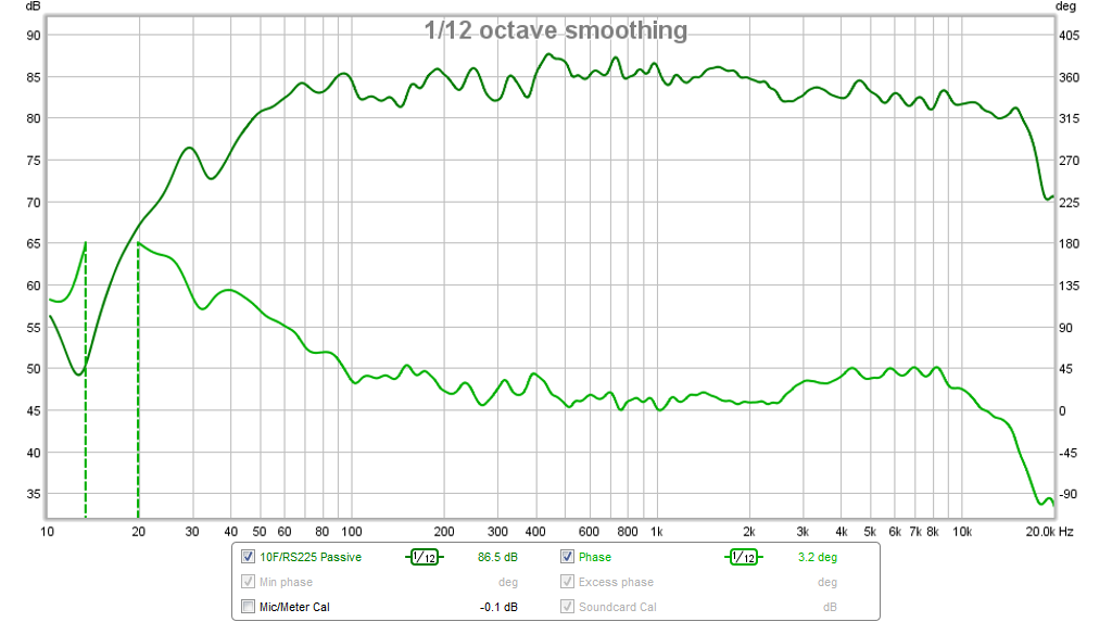
frequency response and phase using passive XO:
554262d1465632129-subjective-blind-abx-test-enabled-ff85wk-round-6-10f-fast-phase.png


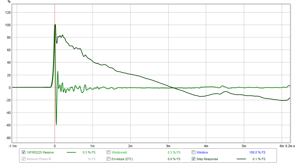
Impulse and step response:
554264d1465632129-subjective-blind-abx-test-enabled-ff85wk-round-6-10f-fast-ir.png


Latest tweaks to the passive 1st order XO with simulation files:
10F/8424 & RS225-8 FAST Ref Monitor - Page 95 - diyAudio

656203d1515700364-10f-8424-rs225-8-fast-ref-monitor-xrk971-10f-rs225-fast-schematic-jpg


656204d1515700364-10f-8424-rs225-8-fast-ref-monitor-xrk971-10f-rs225-fast-freq-jpg


Edit Dec 3, 2018: BOM for XO is here.

Edit: Dec 27, 2018 - Wxn just built a pair using SB23NRXS45-8 and TG9FD-4 with DSP from a DCX2496 here. The results look great and he did a great job on the cabinet:
724817d1545927339-10f-8424-rs225-8-fast-ref-monitor-img_20181216_214834-jpg


Nice waterfall:
724814d1545926498-10f-8424-rs225-8-fast-ref-monitor-waterfall-png


Edit: Dec. 27, 2018 - I should have mentioned that Aatto built a nice set using the SB23NRXS45-8 with 10F/8424 as well but using a bass reflex box and miniDSP and also with passive XO, but can't remember what he is currently using here:
684637d1527970725-10f-8424-rs225-8-fast-ref-monitor-_dsc6937-jpg


Also, forgot to mention the nice set with RS225/10F that I built in espresso brown stain - these are working out real well as the WAF is excellent as evidenced by the fact that they are upstairs next to the TV 🙂 :
692536d1531955116-10f-8424-rs225-8-fast-ref-monitor-abd2023f-99ce-4eee-bca1-71d043d3a184-jpeg


And of course, here is my current setup. These have been my main speakers for over 2 years now and, I keep coming back them because they sound so nice and balanced. The sharp percussion and wonderful stereo imaging also bring me back. Here they are in my speakerlab, now re-done post basement flooding (back in July 2018) with a new engineered wood flooring, so the echos are a mess and sound treatment is definitely needed now that carpet is missing. Looks nice and clean though - the clutter is building up again (mostly foam core speakers in storage around the corners).
717764d1543098044-10f-8424-rs225-8-fast-ref-monitor-speraker-lab-post-flood-01-jpg


Edit Dec 16, 2019: Thanks to JPS64 for making a super layout for the XO PCB. This will make building this speaker that much simpler.
802499d1576506546-10f-8424-rs225-8-fast-waw-ref-monitor-10f-rs225-xo-pcb-layout-v1-0-eagle-jpg


Edit Dec 21, 2019: new TL floor stander for RS225:
10F/8424 & RS225-8 FAST / WAW Ref Monitor

Measurements of TL here.

803725d1576909032-10f-8424-rs225-8-fast-waw-ref-monitor-10f-rs225-fast-tl-render-png


Edit Dec 22, 2019: Just wanted to remind folks that there was a design made for this speaker XO with an RS100-8 and RS225-4 here:
10F/8424 & RS225-8 FAST / WAW Ref Monitor

660274d1517604025-10f-8424-rs225-8-fast-waw-ref-monitor-rs100-8-rs22-4-fast-500hz-transient-perfect-xo-jpg


Edit Mar. 20, 2020: Revised plans for the TL in all 3/4in BB plywood.
826339d1584679921-10f-8424-rs225-8-fast-waw-ref-monitor-rs225-tl-0-75inply-v2-jpg


Photo of the TLs in action next to the sealed version:
838913d1588149174-10f-8424-rs225-8-fast-waw-ref-monitor-10f-rs225-fast-tl-build-04-jpg


Edit March 30, 2020: Vistaton B80 Variant with modified XO
828413d1585383617-10f-8424-rs225-8-fast-waw-ref-monitor-b80-rs225-fast-build-finished-04-jpg

828798d1585500885-10f-8424-rs225-8-fast-waw-ref-monitor-cb2a9f2d-ed27-4caf-be57-1dae2c081ea2-jpeg


Edit May 19, 2020: this is the XO for the 4ohm RS225-4. You can use your favorite 8ohm 3.5in full range on top. Just make sure it’s 8ohms and adjust R1 to taste.

660274d1517604025-10f-8424-rs225-8-fast-waw-ref-monitor-rs100-8-rs22-4-fast-500hz-transient-perfect-xo-jpg


Edit July 24, 2023: Keantoken developed a crossover specific to the TC9FD-8 to be used in this speaker with the RS225-8. The response looks very smooth and has a wonderful step response. More info here:

https://www.diyaudio.com/community/threads/10f-8424-rs225-8-fast-waw-ref-monitor.273524/page-196

Schematic:
1688172695823-png.1188269


Measured frequency response appears to have 1st order XO near 1500Hz.

crossover-response-2-png.1190875


Nice stuffing/padding plan collected by GUJoe:

1701065448513.png

Attachments

  • 10F8424-RS225-FAST-Freq-1m-Sealed.png
    10F8424-RS225-FAST-Freq-1m-Sealed.png
    32.3 KB · Views: 52,063
  • 10F8424-RS225-FAST-Freq-1m-BR-xmax.png
    10F8424-RS225-FAST-Freq-1m-BR-xmax.png
    13.6 KB · Views: 50,569
  • 10F8424-RS225-FAST-Group-Delay-BR.png
    10F8424-RS225-FAST-Group-Delay-BR.png
    23.6 KB · Views: 48,164
  • 10F8424-RS225-FAST-Bracing-TL.png
    10F8424-RS225-FAST-Bracing-TL.png
    476.5 KB · Views: 51,566

Dividing MM Carts into electrical parts with individual Transfer Functions

In a joined effort, Bill, Dagfinn and I went into much detail by developing replacement diagrams for MM cartridges, divided into two parts, first the output section with coil, that we called the Generator, and second for the complete Cantilever assembly.
An achievement never realized before to the best of our knowledge.
Having developed the transfer functions for both both parts, we were able to prove that these two parts don't "see" each other, in other words, the external load on the Generator does not influence the Cantilever's movement in any way.
Another benefit by having the replacement diagrams, was that it was now possible to find the optimal load in LTSpice for a specific cartridge as regards to it's FR.
Because being too long to put it in a posting, we have added the results in the attachment as a PDF.

Happy reading,

P.S. A few typos haven been corrected and further explanation has been given to indentation.

Attachments

Port Design Question

I have been playing with WinISD and have decided to attempt to design a speaker with a slot port. This is what I have made in SolidWorks pretty quickly. The slot is 1in x 8in with a total length of 32in measured from the centerline of the port. I included rounded corners to hopefully lower air speed.. I am asking here if this is realistic and if this works. I found a woofer that I could use to tune the enclosure to 25 Hz.
These are supposed to be decent-sized speakers. The total dimensions of the enclosure is 27x13x9.5, this is a section view to show the port path.
1745700250774.png

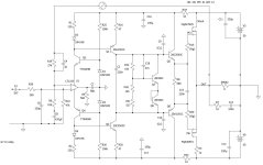
Fast MosFET amp with LT1223 opamp front end

I was following Ian Hegglun's thread "Towards a wideband non switching Auto Bias power amp",
and I was inspired by one of his ideas - Alexander-type input stage and VAS based on op-amp LT1223.

I wasn't familiar with this op-amp, as it seems too fast for typical power amplifier.
There is no point to use expensive ($10.00), high slew-rate op-amp, just to throttle it
later on in order to make the amp stable.

But, if it's driving VAS not from the output, but via rails (like Alexander amp),
the whole amp is more stable and less temperamental.
This amp here shows slew rate of well over 200 V/us, and it's a very simple schematic.

My past attempts show that it's very difficult to actually build stable amp that
can achieve slew rates over 150 V/us. This is first amp I see, that shows phase margin over 75, and
also decent gain margin. In the sim, it seems to be solid, well behaved amp.
So I think I'll give it a try.
First, I came up with LatFet version (dual-die Exicons ECW20N20 & ECW20P20) - that's the one I'm
going to build, and later on with HexFet version.
Both versions show similar results in LtSPice.
Noise floor (1kHz FFT) is at -280dB, and all harmonics are below -120db (inaudible).

Update 29 March 2025: Based on the actual build, C4 should be removed. With it, amp had tendencies to oscillate (when using LT1223).
I keep it in the schematic, purely for the simulation purposes. Apparently LTSpice sim is slightly disconnected from reality.
Also, gate resistors have been changed to R2: 220 Ohm and R3: 100 Ohm.

Update 30 March 2025: If using different op-amp, C4 should be present (2pF).
The following op-amps have been confirmed to work correctly (besides LT1223):
LT1357, TLE2071, TLE2081, AD711, OPA134, LF356. These op-amps were not simulated in LTSpice, just confirmed that they seem to work OK
in the real amp. The schematic and sim may not be optimal for these op-amps, so there might be some space for improvement
if using non-LT1223 op-amp.

Update April 2025: Actual amp has been built and finished. See Post #47.

Update April 2025: HexFet version has been built and tested. See Post #55.


lt1223_schematic.03.ok.jpg


thd_1khz.jpg


fft_1khz.jpg


olg.jpg

Attachments

For Sale Spring Cleaning DIY Speakers/Drivers

Hi,

I'm trying to offload several DIY audio parts and even a pair of full speakers. I will charge actual shipping/insurance costs to your destination based on your preferred shipping arrangement (coming from Aurora CO 80016). Here are the items I have for sale:
Sold - $1000 - DIY Aleph J in 5U Chassis
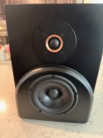
$1000 - DIY Bookshelf Speakers with 15W/8530k-00 ($220/ea retail) + Seas Millennium ($482/ea retail) + Jantzen Crossover
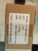
Free - Pair of planar magnetic tweeters of unknown manufacturer - will ship with first person to buy > $100 worth of gear from me
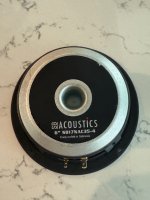
$110 - Pair SB Acoustics SB17NAC35-4 (1 impedance measurements never mounted + 1 BNIB)
$180 for 4 or $100 for 2 New Peerless HDS 830875 Midwoofers (1 taken out of cardboard to look at but never mounted or measured)
$180 for 4 or $100 for 2 used Seas ER19RN-TRD mid woofers (These were in surround sound speakers for about 2 years)
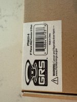
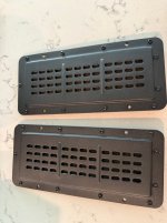
$80 for pair of GRS PT6825-8 8" planar mid/tweeter (new)
$70 for pair of GRS PT6816-8 8" narrow planar mid/tweeter
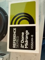
$80 for pair of Dayton RS52AN-8 2" Dome Midrange (new)

$1500 for all remaining

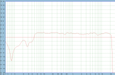
While there is a bit of ambiguity purchasing a DIY loudspeaker designed by me. All I can say is that these sound excellent. Except for overall output level, everyone who has listened to the bookshelf speakers prefers their sound over the pair of Kairos (Jeff Bagby design) I built previously. They image very well and don't require any EQ to my ears unless I use them in my office as desktop speakers. I've built lots of speakers from LX521, Troels "The Loudspeaker" and really find their sound signature second only to the LX521. "The Loudspeaker" was fun because it had no practical output limit in a domestic setting. Of course they are 5.5" drivers so best crossed over to subs if you want to play loud but without or for near field they sound fantastic. There is just something special about this pairing of great drivers. I've attached the final simulated response captured as a screenshot. I can provide design files in SoundEasy but can't launch the app anymore due to lack of support on modern computers. If I remember correctly I did end up padding the tweeter down a little more by ear but you can always manipulate L-pad to your liking.

For references check out my eBay/Reverb rating (user jf4828 on both). I'm happy to do transactions through those platforms if you prefer but would have to charge a bit more to cover selling fees....

I'm happy to snap some more photos if needed; just let me know what you'd like to see 🙂

Joel

Attachments

  • IMG_0943.jpeg
    IMG_0943.jpeg
    620.9 KB · Views: 109
  • IMG_0954.jpeg
    IMG_0954.jpeg
    735.7 KB · Views: 38
  • IMG_0953.jpeg
    IMG_0953.jpeg
    788.6 KB · Views: 37
  • IMG_0952.jpeg
    IMG_0952.jpeg
    704.5 KB · Views: 41
  • IMG_0951.jpeg
    IMG_0951.jpeg
    528.8 KB · Views: 39
  • IMG_0948.jpeg
    IMG_0948.jpeg
    546.2 KB · Views: 39
  • IMG_0947.jpeg
    IMG_0947.jpeg
    558.6 KB · Views: 42
  • IMG_0946.jpeg
    IMG_0946.jpeg
    618.8 KB · Views: 40
  • IMG_0945.jpeg
    IMG_0945.jpeg
    558 KB · Views: 37
  • IMG_0944.jpeg
    IMG_0944.jpeg
    728.8 KB · Views: 44
  • IMG_0942.jpeg
    IMG_0942.jpeg
    640.7 KB · Views: 38
  • IMG_0941.jpeg
    IMG_0941.jpeg
    539.2 KB · Views: 37
  • IMG_0940.jpeg
    IMG_0940.jpeg
    495.6 KB · Views: 43
  • IMG_0939.jpeg
    IMG_0939.jpeg
    552.8 KB · Views: 62
  • IMG_0938.jpeg
    IMG_0938.jpeg
    492.8 KB · Views: 54
  • 15W-Final-Response.png
    15W-Final-Response.png
    62.1 KB · Views: 50
  • BookshelfPlans.pdf
    BookshelfPlans.pdf
    462 KB · Views: 28
Projects by fanatics, for fanatics
Get answers and advice for everyone wanting to learn the art of audio.
Join the Community
508,473
Members
7,921,247
Messages

Filter

Forum Statistics

Threads
407,846
Messages
7,921,247
Members
508,473
Latest member
Ala Electronics