Does anyone have a schematic, (or sell a PCB), for a circuit that can monitor the voltage drop across a 1 ohm sense resistor and output a latched high output if the voltage goes over the pre determined set point? Whereby if the voltage rises over a set point it will output a latched high that can then be used to energize a relay that cuts mains power via its NC contacts. For example your amplifier loses its bias for some reason, your four 300B tubes worth $1,000 start to melt down and you want the whole amp to simply turn itself off. I see that the INA300 chip does exactly what I need, but I don't want to start from scratch on that.
I'd use an arduino to that, powered by it's own psu and equipped with some display. The arduino may
be used to control the power and after sensing overcurrent should display the reason for power down in the
display, that's why it should have it's own psu.
Just breaking power without any more disgnostic outputs won't tell why the amp just shut down.
be used to control the power and after sensing overcurrent should display the reason for power down in the
display, that's why it should have it's own psu.
Just breaking power without any more disgnostic outputs won't tell why the amp just shut down.

If that's solely the only function of the circuit, I would imagine it would be obvious why the amp shut down. That's just my .02.Just breaking power without any more disgnostic outputs won't tell why the amp just shut down.
You can buy simple comparator PCB kits online, no problem. But a circuit that turns off the power when the current is too high sounds a lot like a fuse... ahem
You could consider fusing the cathodes of the tubes, and maybe the anodes. I think that if the 1 ohm resistor is sized (in terms of watts) properly, that might work as well, eg as a fuse. This is assuming that you've got that resistor in between the cathode and ground.
Of course, that's not an easy reset 🙂 But I would imagine that losing bias would not be a common thing to have happen, and if it did you'd probably need to open up the amp anyways.
Edit: but yeah, an inexpensive SBC that has enough oomph to drive a mains relay could do that with very few parts.
Of course, that's not an easy reset 🙂 But I would imagine that losing bias would not be a common thing to have happen, and if it did you'd probably need to open up the amp anyways.
Edit: but yeah, an inexpensive SBC that has enough oomph to drive a mains relay could do that with very few parts.
Few years ago (during the Covid) I played with fixed bias protection problem.But a circuit that turns off the power when the current is too high sounds a lot like a fuse... ahem
Simulated this schematic, but I've never tried it in practice.

BTW I used fix biased SE amps for decades ... never needed anything like this before.
Yes, arduino IS an inexpensive SBC that can control a relay and has analog input(s)%%%snip%%%
Edit: but yeah, an inexpensive SBC that has enough oomph to drive a mains relay could do that with very few parts.
... For example your amplifier loses its bias for some reason, your four 300B tubes worth $1,000 start to melt down and you want the whole amp to simply turn itself off.
If you want to protect in the event of ''lost bias'' you could just power a relay off the bias voltage that opens the heater/filament circuit and you'd hear the loss of the music. You want enough bias filtering capacity to make that loss a slow and smooth process, but drop the heater quickly.
Yup. So is a Teensy, lol and there are others, including very inexpensive older Raspberry Pi models.Yes, arduino IS an inexpensive SBC %%%snip%%%
Anyways, any of these that include an ADC and a single digital output pin can be used for this purpose. It should be a trivial exercise to use any of these SBC to perform threshold detection in code that will drive the logic for a relay.
But a circuit that turns off the power when the current is too high sounds a lot like a fuse... ahem
So simple, just disconnect the $250 tube! Thanks Merlinb! (excerpt below circled red):
Patrick Turner (RIP) had circuit schematics for this very purpose on his website. The complete mirror site is here https://atrad-audio.co.nz/turneraudio/www.turneraudio.com.au/index.html there are several examples under various projects.
If the tubes are pentodes, fusing the plate supply will leave the screen grids hanging out there if the fuse opens, tasked with providing a current they are not made to handle. This would not be a problem if the output stage were ultralinear, since both plate & screens would disconnect when the fuse opens. I'd fuse the AC voltage driving the power transformer and not any of the DC voltages. Fusing a high DC voltage could cause a plasma in the fuse to ignite, since there are no zero crossings to extinguish the arc. The plasma could cause a fire, and conduct enough current long enough to allow damage to the circuit the fuse is there to protect. A fuse in a low voltage circuit would likely be okay, since a plasma would likely not form in that setting. Fusing the cathode circuit could cause excessive heater to cathode voltage when the fuse opens, possibly ruining the tube.You could consider fusing the cathodes of the tubes, and maybe the anodes. I think that if the 1 ohm resistor is sized (in terms of watts) properly, that might work as well, eg as a fuse. This is assuming that you've got that resistor in between the cathode and ground.
Of course, that's not an easy reset 🙂 But I would imagine that losing bias would not be a common thing to have happen, and if it did you'd probably need to open up the amp anyways.
Edit: but yeah, an inexpensive SBC that has enough oomph to drive a mains relay could do that with very few parts.
That´s why I use LM339 comparators set up as window detactors with SCR latches to monitor the differential between B+ and neg bias voltages on my power amps. That´s one method. .....all this dirt easy stuff but like Turner some can be fairly complex. The SCR latch can either switch-in a common cathode resistor or go for the whole hog disable B+ function, which is my preferred. This method also protects against a higher mains voltage, eventually a higher B+.The circuit made to reset by either cold or hot power reset. The other caveat to avoid false tripping or inhibit function when using SState sensing is the neg bias supply must appear before the B+.Just breaking power without any more disgnostic outputs won't tell why the amp just shut down.
Music wise, I´ve come across tube amp systems handling extremely heavy bass beat note headrooms that can easily overload an output stage which with other methods can result in false tripping.
One method I´ve used is current sense monitoring each power tube within a specific parameter and when drifting out of spec actuates a window comparator eventually to a flashing led ajacent to the suspect drifting tube. This requires a long TC integrator DC filter, plus trip voltage comparator but I found this method can be fooled by using loudspeakers with lower impedances. (Maybe not such a bad idea after all)
Tubes are pretty robust with abuse but reliability with fuses is not. As others mentioned, P Turner configured many circuit ideas on these issues.
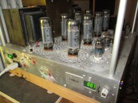
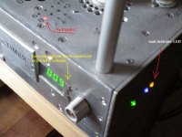
The pics below one close-up of sensing section of the 500W power amp. A close up of the "fault" pic indicates No8 tube (deliberately fitted) has failed accompanied by a fault yell LED on front panel. This behemoth amp uses the total B+ shutdown function.
.........Ingenuity abounds......
Bench Baron
Attachments
I've used Pat Turners circuit in a few amps: saved my ar se a few times especially whilst testing. It does need a separate tfmr & PSU to power the circuit though. On the positive side it works & uses a few resistors & caps as well as a thyristor.
Andy.
Andy.
Thyristors or SCR´s may be historical but make excellent fast switches and latches, but the smaller types TO92 sizes etc require careful layouts around sensitive gate-cathode to avoid spurious triggering, esp when lab breadboarding. I always use them with small relays in post AC rectifier circuits (100Hz) as the back emf of the relay keeps the device once triggered, into conduction. Break the power and relay releases with the specified drop out time. I´ll dig out a circuit or two.
To require resetting once latched, the power off function has to drop below the holding current which makes a good equipment protection feature. (I used them alot in tram and train motive power drives of the early 1970´s and are very reliable without latch up, a parasitic failure mechanism of IGBT´s, and when these big ones fail, they are akin to handgrenades. This is when power electronics becomes a dangerous occupation).
Bench Baron
- Home
- Amplifiers
- Tubes / Valves
- Overcurrent protection monitor for a direct bias amp