Project Overview:
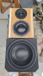
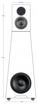
1. The project will be for a 'modular' (I will explain this below) 3 way plus subwoofer configuration in a 0.56 cubic foot Dayton/Denovo cabinet.
2. The cabinet will share the 7" or 8" woofer and whatever midrange is selected.
3. The cabinet's interior is limited to a 7" cutout but given that the actual driver will be mounted in the baffle and that it tapers toward the magnet I can probably get up to 7 1/4 inch cutouts in this cabinet by using a dremel to lightly remove small 1/8" areas from the MDF of the interior walls on each side (maximum) without violating the integrity of the cabinet.
4. I am going for a 'sealed' configuration for easy integration with the 2 x subwoofers.
5. The speaker will be 100% active and audiolense XO automatically time aligns to minimum phase or linear phase depending on your choice so from a crossover perspective all I have to feed audiolense are a few things as shown below. Audiolense will automatically flatten the response using psychoacoustic algorithms to whatever curve you've drawn up for the overall speaker response peaks and such are automatically handled. Dips however are a concern as I prefer only to cut not boost so big dips likely will reduce overall speaker sensitivity.
a. The crossover point between each driver.
b. The 'octave width' of the crossover point. I can make digital slopes that are EXTREMELY steep, I've successfully used 0.5 octaves for the crossover point width before.
c. A target response config/room curve i.e. whatever I draw, the harman curve, B&K curve, toole curve, etc.
d. The 'correction' profile i.e. if I want per driver time alignment, phase type, number of taps per correction file, etc.
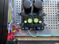
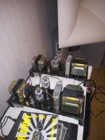
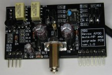
6. Each driver will have it's own dedicated amp channel of 80wpc capable of 4 or 8 ohm loads so likely 4 is preferred in all cases to get the additional sensitivity out of the driver.
7. The room is my office and is maybe 10' x 16'. I sit at one end of the narrow range of the rectangle.
8. The speakers will be stand mounted 4-6' out from me on either side.
9. I listen at moderate levels, ideally I would like to target output levels of 89-94db with very low distortion or strain on the drivers, I don't really care about MAX SPL, what is more pertinent is that I be able to listen in that 89-94db range with no audible strain/distortion.
10. I would like to spend under or around $100 per midrange or midbass driver. If there are compelling reasons to spend more I will entertain them for sure.
11. I like 'detailed' in a driver versus 'analytical' i.e. I want a lot of detail but not to subjectively enter analytical territory where any music that isn't perfectly recorded sounds granular/grainy.
12. I listen to all types of music. This will be 100% for music not HT.
13. Given that my office is an audio laboratory I don't care - at all - about driver appearance or WAF. These drivers can be as ugly as we want.
Alternately:
I could make a dedicated cabinet for the 8" woofer that stands on it's own and then 'stack' the other modules for the midrange and tweeter on top of it if we encounter cabinet volume limitations that are compelling. I would use a piece of ISO rubber (Bridgestone ISO pond liner) between each 'module' for isolation.
Details:
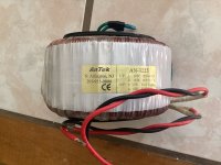
1. Subwoofers are dual M&K MX70B's. They are about -4db at 20hz and are +1-2db once you hit 30hz or so.
2. Active crossovers will be implemented using Audiolense Convolver and Audiolense XO.
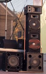
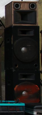
3. By modular I mean this. 1. My cabinet has around 6 pairs of front baffles of the same size that have been pre-cut that I can swap in and out using 6 x machine screws that go into threaded inserts in the actual cabinet. This lets me swap speaker configurations at any time and then simply select the convolution file that matches to that 'speaker'.
4. On the baffle I intend to have a cutout for the 8" bass driver and above it the cutout for the midrange driver. The tweeter/waveguide will sit on top of the speaker. I have a ton of little precut stand alone baffles on L brackets that I set on top of this stand mount making it 'modular' in the tweeter section as well.
5. I usually cross both M&K subs at around 80-120hz (I know I'm getting a little directional if go over 80hz) depending on the configuration of the drivers currently in the box/swappable baffles.
Questions:
1. The speakers will be angled facing me on each side. Does this mean that since I'm always on access that beaming of driver is less of a variable or no variable as far as driver selection goes?
2. Should I build sub-enclosures for the midrange inside the box or is it fine if the midwoofer/midbass driver share the same air volume in the sealed enclosure? This will likely be a variable on if I share the cabinet or go fully modular with separate enclosures.
3. Driver selection....bring it! I'm open to all manner of suggestions, the ones I have suggested were just based on research.
4. Crossover points, again, bring it! I'm open to suggestions.
Driver Selection Options:
Woofer/midbass
1. Dayton RS225-4
a. I'm assuming I'd go 4 ohms go squeeze as much out as I can unless there is a compelling reason not to.
b. Do I go for aluminum or paper?
c. Perennial recommendation regarding low distortion and high value in many threads.
d. Looks like I can get flat response from just short of 100hz (which is fine) until maybe 1500-1600khz at which I'll need to hand off to the midrange. I am far more likely to do this at around 500hz or so.
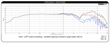
e. Dayton RS225p-4a frequency response below. Not sure which one is preferable, would love to hear advice:
2. Dayton PA-200.
a. High output pro woofer.
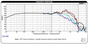
b. Efficient and nice looking performance graphs for this application see below:
3. Peerless by Tymphany 830869 8" Nomex Cone HDS Woofer - Cutout too large at near 7.5 inches.
4. FaitalPRO 8FE200 8" Professional Midbass 8 Ohm and/or FaitalPRO 8FE300 8" Professional Midbass 8 Ohm
- Maybe an option but Sealed 43 is slightly over 100 hz which isn't optimal. Given that it's efficient I could probably flatten the entire frequency to compensate for it and still not have significantly lost efficiency.
5. Peerless SLS 830667, 8" - Frequently recommended option, the Dayton seems better based on graphs/specs as far as I can tell.
6.
SB Acoustics SB20PFCR30-4 8" Paper Cone Woofer- 4 ohm-Looks really good for a really low price but who knows how it sounds/distortion specs.
7. Classic P21WO20 8" Woofer Poly Cone, looks like a remake of the scan-speak by Madisound.
8. SB Acoustics SB23NRXS45-4, 8" Woofer
9.
Scan-Speak Discovery, 22W/4534G00, 8" Midwoofer,
4 ohm
Midrange/Full Range:
1. I already have the venerable Tymphany TC9FD18-08 and Tectonic TEBM65C20F-8 3-1/2" BMR Full-Range Speaker 8 Ohm
2. Dayton Audio RS100-4 4" Reference Full-Range Driver 4 Ohm and Dayton Audio RS100P-4 4" Reference Paper Woofer 4 Ohm - Well loved and commonly used.
3. Dynavox LY401F 4" Full-Range Driver: Fascinated by this driver.
4. Faitalpro FE32: Not sure why I'd pick the Neo but it's in here in case I'm missing something.
5. Faitalpro FE35 This seems like a stellar candidate, might be near the top of my draft pick list. I'm not quite sure how to mount this to avoid issues/diffraction.
6. Tymphany NE149-04 seems popular but inefficient to a degree but not prohibitively so.
7. Tang Band W4-1337SDF 4" Titanium Full Range Speaker
8. Tang Band W5-2143 5" Paper Cone Full Range Driver 8 Ohm
9. Tang Band W5-1611SAF 5" Full Range Speaker
10. Tang Band W4-2142 4" Paper Cone Full Range Driver 8 Ohm
10. Peerless By Tymphany NE123W-08 4" Full Range Woofer Speaker again seems popular but inefficient.
11. Dayton Audio RS52FN-8 2" Reference Fabric Dome Midrange 8 Ohm/Dayton Audio RS52AN-8 2" Reference Aluminum Dome Midrange - Lots of discussion regarding these.
12. Visaton B 80 3.3" Full-Range Driver 8 Ohm
13. SB Acoustics SB12MNRX2-25-04
14. SB15MFC30
15. SB15CAC
16. BMS 5S117 $137
17. Scanspeak Discovery 10F/4424G, 4" Midrange 4 ohm
18. Lots of recommendations for Morel MDM55 dome.
19. Beyma 3FR30
20. b&c 3.5NDF26
21. Scanspeak 15M/4624G Discovery, 5.5" Midrange
Crossover Points:
1. Woofer to midbass/woofer anywhere from 80-120hz, lower is better.
2. Midbass to midrange around 500hz to avoid having a crossover point in the critical lower end range unless I'm off target on this.
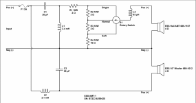
3. Midrange to tweeter -> Given that this is a modular design the ability to crossover higher is better to maximize my choice of tweeters and reduce the strain upon them. This is all TBD. Probably the most demanding tweeter that I own as far as needing to be crossed over high is a pair of cheap Foster E100T10's whose response is below. I don't HAVE to design around these, it would just be nice to have them as an option: