There was an amp I worked years ago called the CFH7. More info on that thread here. It was basically a VSSA current feedback front end married to the Class AB hexFET output stage of the FH9. After some mods and testing by other members, most notably, Thimios who identified some oscillations and how to fix them, we went on to make higher output device counts on this amp. We ended up at 2 output pairs (4), 2 drivers, a Vbe multiplier temperature compensation (1), and the input pair (2) for 9 actives. A member added a cap multiplier for each rail to clean up the front end rails which is technically 2 more. The name remained at CFH9 but had a CX designation for the cap multiplier. Technically it’s a CFH11CX2. The naming follows Apex Audio’s convention: C for current feedback amp, F for FET output stage, H for hexFET (vs laterals), 11 for number of actives, we added CX, for cap multiplier, I added the 2 for second generation. A big thanks to the others who provided help, discussions, inspiration, and assistance in testing and layouts: Shaan, Gaborbela, Thimios, Apex Audio, Mjona, MG2016, Ashok, Thiago, Saddevil,… it really was a community project.
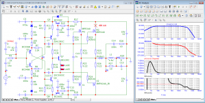
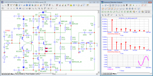
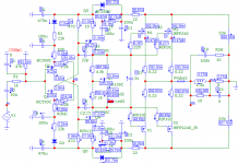
It’s a very simple amp:

But the predicted performance is quite amazing - here is 1W info 8ohms, essentially no distortion (THD is 0.000023% - that’s 0.2ppm - in reality it won’t achieve that due to imperfect models or parts but we get the idea that it can be very transparent given such a low parts count):

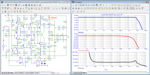
Here is a bit more power 50Vpp into 8ohms:

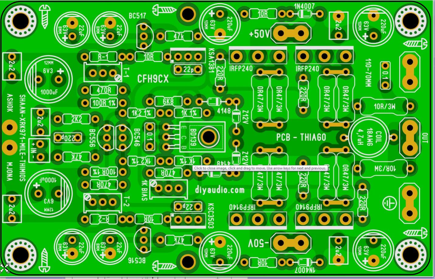
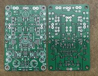
A nice layout was made by Thiago and that has recently been verified to work by fazildiken:
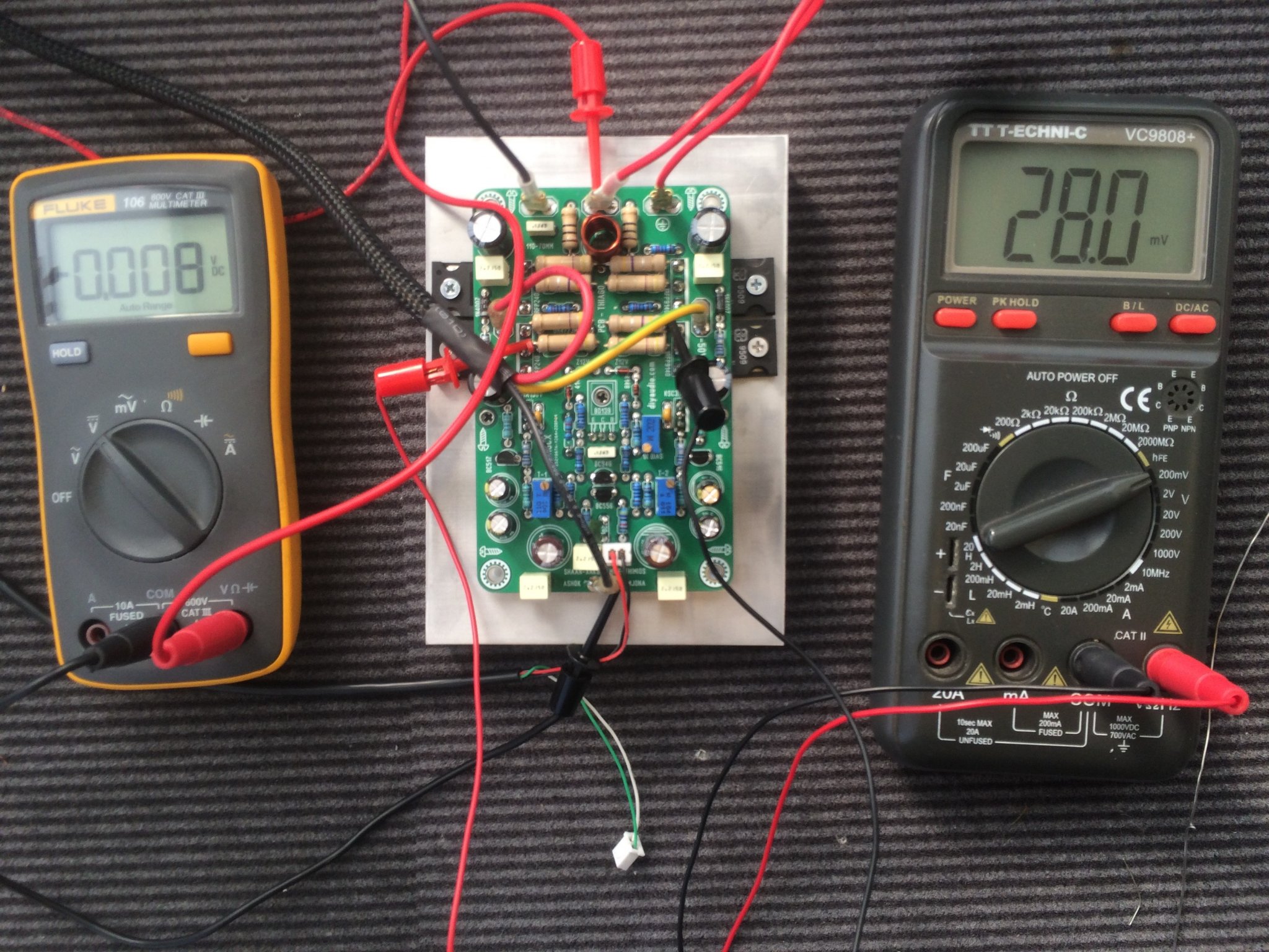
Fazildiken’s build:
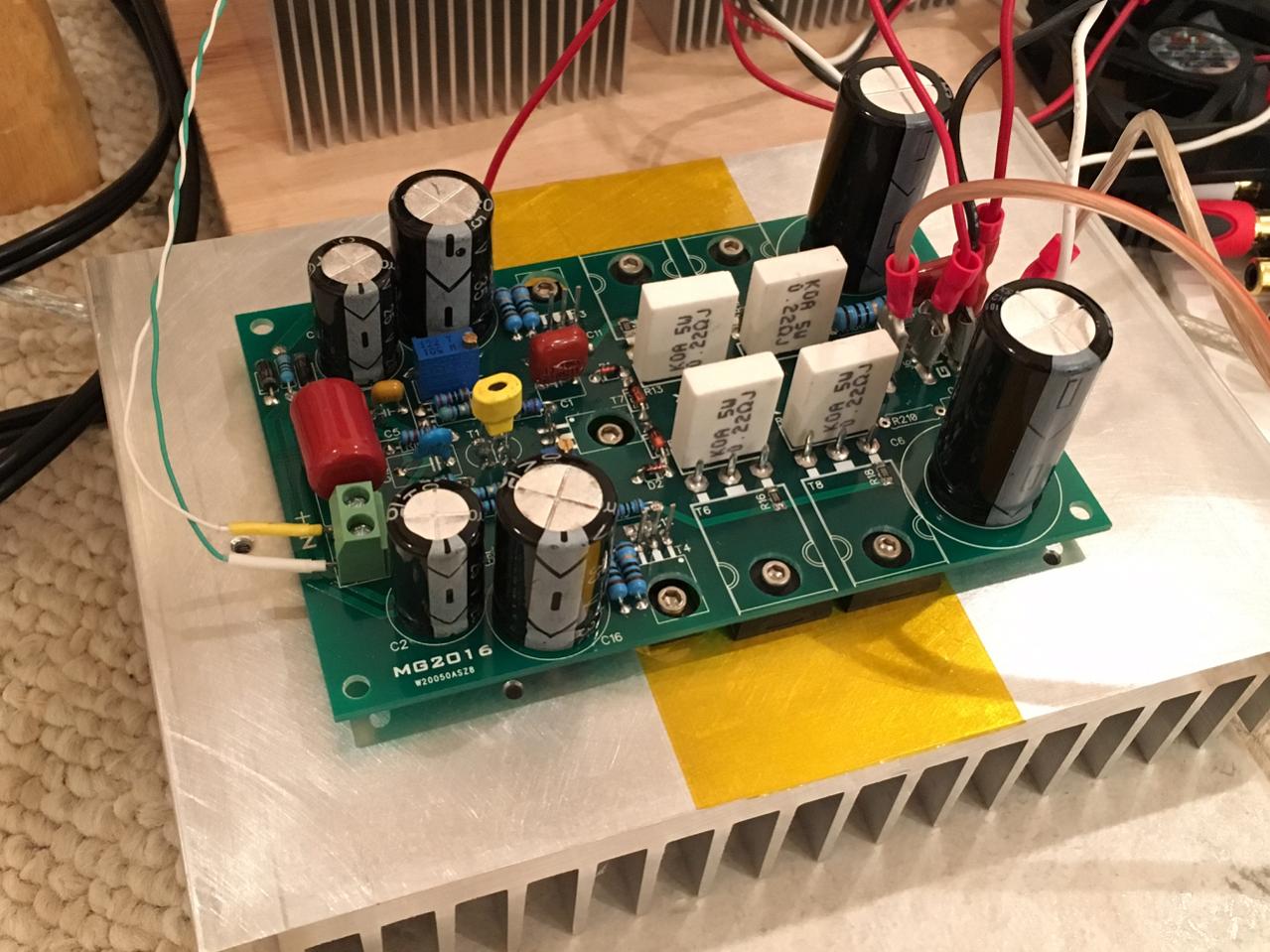
This was my CFH9 with MG2016’s layout being tested:
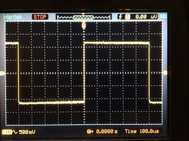
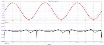
Square wave test:
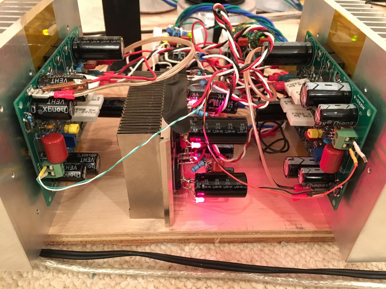
I even had it running as stereo on a plank amp:
I am thinking of taking this as a starting point and doing a few more mods to it and maybe a new layout one of these days. No rush on this project but just getting it out there and to start thinking about it.
It’s a very simple amp:
But the predicted performance is quite amazing - here is 1W info 8ohms, essentially no distortion (THD is 0.000023% - that’s 0.2ppm - in reality it won’t achieve that due to imperfect models or parts but we get the idea that it can be very transparent given such a low parts count):
Here is a bit more power 50Vpp into 8ohms:
A nice layout was made by Thiago and that has recently been verified to work by fazildiken:
Fazildiken’s build:
This was my CFH9 with MG2016’s layout being tested:
Square wave test:
I even had it running as stereo on a plank amp:
I am thinking of taking this as a starting point and doing a few more mods to it and maybe a new layout one of these days. No rush on this project but just getting it out there and to start thinking about it.
Last edited:

https://www.diyaudio.com/community/threads/cfh7-amp.294834/post-7090185
The bias current is running pretty hot at 824mA (412mA per device) for about 90W dissipation per channel
I would like to have 2pairs of the pcb
Looks like you can have two pairs of boards as I don’t see anyone else asking for them. PM me and I’ll get your info.
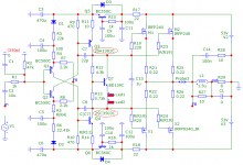
I apologize to the author of the topic, I inadvertently did not replace two models of transistors
Attachments
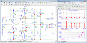
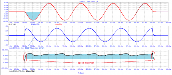
What arousal are you talking about?What is the excitation frequency? Looks like you are way up in the ultrasonic range?
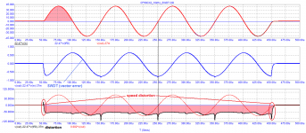
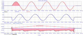
What is sine wave excitation for above FFTs? Looks like 10kHz (based on 100usec peak to peak timescale) in which case second harmonic is 20kHz and third is 30kHz etc. ultrasonic and inaudible to most. Most people show FFT for 1kHz excitation. Also, what is meant by speed distortion? Is this distortion due to a rapid step response?
My sims show 0.0008% THD for 50Vpp into 8ohms for 1kHz excitation.I apologize to the author of the topic, I inadvertently did not replace two models of transistors
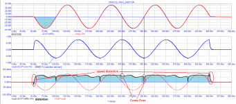
... what is meant by speed distortion? Is this distortion due to a rapid step response?
This is a consequence of the slow transient response, the result of a long signal propagation delay (Group Delay or time Propagation Delay).