Oscillations and other minor issues in LM4780 hifidiy.net PCB

Recently I made LM4780(obsolete) chipamp on a hifidiy,net PCB (no further info on this site about schematics, etc.) as per standard BOM values printed on the PCB itself later changed after running into oscillations issues. LM4780 pin 11 was broken (-V) but "patched". As it was lying in my drawer for the past 10yrs, I ordered PCB from Aliexpress to finish these projects. This PCB lacked any place for spk gnd and input capacitors. So I connected spk gnd to supply gnd and somehow connected input DC blocking caps . I have also recv. XY LM3886 PCBs for another pair of LM3886. Any suggestions for improvement will be incorporated in the final build of both chipamps.
During initial testing phase itself the IC would get crazy hot and put out 1.6V DC at both outputs ,with very faint audio and heavy static and weird noises. So I slapped in 18K resistor +47pF ceramic series in feedback, as I had only those available in my drawer. The DC got reduced to 0.75V but still unbearable noise levels. Then I soldered 47pF on both + and -ve inputs each. LM datasheets recommends 200pF between + and -ve inputs and 20K +50pF The amp is now behaving normally with one ch. 18mV DC and other 110mV DC heatsinks runs cool to touch. No zobel was used , I just installed 2.2R resistor just to protect from accidental short. I will be making changes as per datasheets BOM incl Zobel in the final build
I was wondering how could other diyer's iteration of such PCBs would have turned out, as no ceramic pF for reducing oscillations are used in even Audio Sector PCBs too.
My question is -
1. Is 47pF ok on + and -ve inputs? Should I bother to change it to 200pF?
2. Does the large heatsink, directly mounted to metal tab which is connected internally to -V, plays any role in noise or oscillations. Should I isolate it using Mica washer?
I won't be using any boutique parts, this project is just to make a budget biamp, based on single LM4780 configured as stereo / dual for highs, & pair of LM3886 for mids and lows with lower carbon footprint in mind.( +/- 20V ). I will be extensively testing them first on elcheapo speakers and dummy loads for oscillations to avoid damaging tweeters.
Thanks

Attachments

  • WhatsApp Image 2022-08-25 at 2.00.18 PM.jpeg
    WhatsApp Image 2022-08-25 at 2.00.18 PM.jpeg
    11.2 KB · Views: 157
  • WhatsApp Image 2022-08-25 at 2.37.33 PM.jpeg
    WhatsApp Image 2022-08-25 at 2.37.33 PM.jpeg
    87.1 KB · Views: 169

Monetizing design. DIY ethos

Just a quick question. Certain that it's been discussed enough. Not sure how to search for it here.

ampslab-spk projects. The designer is prolific. The designs appear well conceived and executed. There is a broad range of price/performance. The site is lacking somewhat in organization. Subsequent versions of namesake projects, such as versions of the Warbler and the Cardinal, are seldom compared clearly to one another. I've also had zero luck getting any response to numerous emails to the site.

That said I have a difficult time finding much commentary on these designs. Is this simply because they are only 'semi-diy' according to diy ethos since the crossover design itself is pay-walled and cannot/should-not be shared freely? I am expressly not criticizing this enterprise. Just a question about diy ethos.

New aftermarket radio ground loop issue

I have a new aftermarket radio I just installed in the car it features carplay/android auto and hdmi in with a rca to hdmi adapter.

I had it professionally installed and everything works fine until I plug in a fire stick to the hdmi input the video and audio work but I get really bad ground loop noises because it needs to get power from a cigarette to usb adapter for power the normal usb ports won't power the stick. I get video and audio but again the noises are really noticeable.

I'm trying to find the right usb isolator for my application but alot of these adapters on amazon say they're rated for 1 or 2v which I believe the stick needs 5v and/or the amp rating is way too low. I'm not an expert and I haven't bought anything yet I just want to make sure I buy something that'll work for this application I don't want to blow the adapter or worse something in the car, any advice would be appreciated.

World's first soundbar?

I stumbled upon this Sanyo msp-5 sound bar that some say it's made in 1981 and believe it or not it works and sound pretty cool for its format.I sent wikipedia this information too as they pretended Altec Lansing was the first to release a soundbar in 1998.They'll probably tell if I'm right or not .If that's not a 2.1 , battery (rechargeable) opperated independent of the signal source soundbar I don't know what is...I dont't have the external power source and I have no ideea if it has charging capabilities.
Login to view embedded media

Attachments

  • 20220822_202049.jpg
    20220822_202049.jpg
    525.5 KB · Views: 112
  • 20220822_202830.jpg
    20220822_202830.jpg
    460.5 KB · Views: 110
  • 20220822_202855.jpg
    20220822_202855.jpg
    612.7 KB · Views: 106
  • 20220822_204117.jpg
    20220822_204117.jpg
    546.1 KB · Views: 116
  • 20220822_205945.jpg
    20220822_205945.jpg
    413.1 KB · Views: 107
  • 20220822_210007.jpg
    20220822_210007.jpg
    390.4 KB · Views: 102
  • 20220822_210035.jpg
    20220822_210035.jpg
    404.8 KB · Views: 102
  • 20220822_210102.jpg
    20220822_210102.jpg
    558.9 KB · Views: 118

Kicker ZX750.1 zener @ Q250?

Found this lil bad boy reading 8 Ω between bottom 2 legs, found it while looking for a problem that is preventing my LM361 from outputting, it’s getting input on both inputs, looks like a wave trying to start at gates of output FETs but noda :/

so while searching I came across this, searching came up with this “39w” @ Q250, seems to be an “rd3mw” a dot-23 39v .3ma Zener? Never seen a zener like this before. Can’t find any in stock either, left pad on board doesn’t look used but I’m not sure so wanted to check with the Kicker gurus 🙂

if I can’t find a sot-23 package can I use something else since left bottom pad doesn’t look used? Like say a glass zener of similar specs, band side being soldered on top pad? (only zener I knew of, guess they come in all forms 😅)

Thank you 🙏🏻

Attachments

  • F34A4A77-1DD6-4D8F-8450-FC4DA3CE2882.jpeg
    F34A4A77-1DD6-4D8F-8450-FC4DA3CE2882.jpeg
    528 KB · Views: 94
  • F4CFE07F-1896-4DC3-B2C7-DA1D4FF5B238.jpeg
    F4CFE07F-1896-4DC3-B2C7-DA1D4FF5B238.jpeg
    113.4 KB · Views: 91
  • image.jpg
    image.jpg
    689.4 KB · Views: 110

about Arcam Delta90 static voltage,

Hi, I have an ARCAM delta 90 amplifier that needs help. The r58 and R59 resistance of the last stage triode emitter is 0.22 ohm. It is tested that the voltage at both ends of r58 is DC voltage of 1mV. Is the real standard 23.1mv? Is the adjustment adjusted through rv1? Attach the circuit diagram,
IMG_0570.JPG
IMG_0569.JPG

Attachments

Adding a remote control?

Very newbie question so my apologies!

I just picked up an Alps Alpine motorized Potentiometer (100k) for a preamp board I’m working on, but I’m curious how I actually go about incorporating a remote to control the volume pot?

I’ve seen a few PCBs (both digital pots and ones that physically move a motorized pot) on Aliexpress but curious if there are any better options out there

And suggestions or pointers are very appreciated!

Thanks 🙂

Question about 'build out' resistor placement in cathode follower

I understand a build out resistor is necessary to keep a cathode follower from high frequency resonance or oscillation when driving capacitive loads (like long runs of cable).

However, I've seen a couple different ways of placing that build out resistor in circuit, so I wanted to ask what happens when you move that build out resistor to different places in the circuit. I drew up an example showing the three I've seen:

1661255819314.png


I usually place Rbo (the build out resistor) as in Ex. A.
I understand that placing Rbo as in Ex. B will add slight additional cathode load, but in use it's pretty much the same as Ex. A.
Will Rbo placed as in Ex. C also act to dampen high frequency resonance with high Cload, as in Ex's A and B? Or will it not work at all that way?

Rotel RA06SE output offset.

Already addressed the "usual suspect i.e. the 100uf caps on the feedback side of the input long tailed pairs.
That snot it. One channel is about 5v positive, other a couple of volts negative. This is of course triggering
the DC protect to prevent speaker flames. Suspicion is on the input pairs (2 x A1016 and 2 x C2362 per channel )
PITA to get a pile of these things to gain match them.
Any other "usual suspects" I have missed?.
M

Total noob here, Hi

Hi All,

I stuble across the forum here and than for years now, and finally registered.
I am an electrical engineer for planing and prototyping industrial machines.

And my hobbies are gaming PCs, home cinema and cars.
But somehow I am just to stupid for electronics, i managed to fix some
dead amps and stuff but can't quite keep up to redesign, modify and especially
improve existing schematics.

Build a phono pre amp a few years ago but it sucked and since then I never really
got into it again until now.


Greetings from austria,
I hope you can help me out with my noop questions here and there.

Jean Hiraga "Le Monstre" Build. Throw me some thoughts and ideas!

Hi to all my DIY'ers out there.

So want to do a quick dirty build of this popular amplifier as now there seems to be a number of kits you can buy at a very reasonable price.

I know there are many versions of this amplifier build circling the forums so i'm sure there's a number of you with great experience who can help.

I got these kits from a nice gentleman named Igor off ebay:

Hiraga "Le Monstre" enhanced 8W (15W) A class Amplifier D.I.Y. Red edition | eBay

Hiraga A Class Power Supply PCB D.I.Y. (Aleph , Zen-X) | eBay


Please see attached schematics and pics:

Screen Shot 2018-02-22 at 23.44.26.png

Screen Shot 2018-02-22 at 23.44.36.png

Screen Shot 2018-02-22 at 23.44.57.png

vPeo0tf.jpg


jGSFT9s.jpg


eMHqGqD.jpg


iSp8dIJ.jpg


So far i have bought 16x25v@47000uf capacitors, i also have two toroidal transformers 160va 2x12v 6.67A.

I have a few questions about the power capabilities of this amplifier, now i know it runs at 12V and i know that probably after rectification and going through the capacitors the voltage will increase, so what i want to know is . will this be ok? Can these amp boards take the high voltage? If not what would you suggest i change in terms of components to handle the extra voltages? Or will it be ok?

I'm not fussed if it's 8w or 15w, i just want to learn how to set it all up i.e the bias and to get it sounding as good as i can with what i have.

I need a soft start and speaker protection modules? I will be building the chassis and heatsinks myself!

Can i buy one soft start board and attach both transformers to it? I dont need to buy two soft starts aslong as the board can handle it correct?

The board i am thinking is this:

220V Class A Power Supply Amplifier Board Soft-Start Delay Temperature Protect | eBay

and speaker protection:

Amplifier DC Audio Speaker Protection Board with Delay Partially assembled | eBay


This should be a quick and easy build really! but happy to do some mods along the way.

On the amplifier boards where R12 and R13 are 5W 1R's i was thinking of replacing these for 10w items so they can handle more load as the voltage with be higher then 12v.

Still learning and enjoying about all of this! At present i have parts for Jean Hiraga super class 30w but taking time to build due to expense! The power supply cost is huge.


Any tips would be greatly appreciated especially with bias settings and generally how to warm and setup the amp once built!

Thanks All

Vish

For Sale Various Octal Rectifier tubes for sale: 5AR4, 5U4GB, 5Y3GT

RECTIFIER TUBES

All tubes come in generic white tube boxes unless otherwise noted. Prices listed for each tube or pair.

Testing data from HIckok tube tester, tested values listed over the tube minimum

Shipping to be decided at time of sale, I will combine shipping.

Tubes are clean and pins cleaned as well.

5AR4 TUBES

ALL SOLD


5U4GB TUBES

-GE PAIR $35/pair $30/pair
date 62-13 92-88/80
date 62-22 92-89/80


5Y3-WGTB (6087)

SOLD

IMG_0953.JPG

Floorstanding 3-way speaker: woofer choice for a newbie

Hi,

I’m still working on my 2-ways, but in my “spare time” 🙂 I’m thinking about a floorstanding 3-way speaker for “general music listening”.

Concept so far:
  • Floorstanding tower shape.
  • Sealed or ported, no preference really
  • Cabinet size can be large, but not coffin-size large.
  • Should have a really good low-end. I will not be adding a subwoofer.
  • Woofer 8'' or 10'' probably. Need to keep the baffle width acceptable.
  • Passive XO
  • Crossover woofer at BSC range
  • Crossover midrange 3k or 4k or so
  • Sensitivity doesn't need to be super high for the ensemble, I'm probably not going to double the W to go super high-sensitivity.
Because the low end is important, I wanted to start with the the woofer selection. The more I read and look at graphs, the more I’m confused.

These are some candidates I found:
  • SEAS Prestige L26RFX/P
  • SEAS Prestige L22RN4X/P
  • SEAS Prestige CD22RN4X
  • Scanspeak 25w/8565
  • Scanspeak 26w/4558t00

Sensitivity: not much difference between them. 88dB, 89dB,..

Material: alu or paper or some paper-hybrid. Word on the street is "alu is more precise, clinical. Paper is warmer." Even if that is true, does it matter with a low-crossed woofer? I can still use a paper midrange.

LF response: the SPL of some of these drops faster than others. E.g. CD22RN4X (only 8 inch). But others remaing stronger for longer like the L26RFX and the 25w/8565.

The 25w/8565 is a bit rocky in the low end though. Is that audible?

1661247537536.png


So given my concept, how on earth do I choose between these drivers? If I were to search more, I'd probably find even more drivers than seem to fit my wishes.

They are too expensive to just buy and test.

Thank you
Vincent

NAP200 Clone materials

Hi all
I bought a ZERO ZONE Naim NAP200 clone but the materials that included differ from the values marked on the board. So instead of 0.22Ω resistors it contains 0,39Ω. The seller on ebay say to adjust the voltage to 5mV across the 0.39Ω (R13) resistor so the idle current calculated to 5/0.39=12.82mA. It is correct? because I read on some threads that this current must be about 22mA so I have to change the voltage from 5mV to 8-10mV. It's OK?
Best Regards
Spiros

Magnat Monitor 802 Improvements?

Hello,

I've been reading posts here for a while now, and now thought to register and ask a few questions.

I have 6 Magnat Monitor 802s in my home cinema and I like them quite well.
They are all driven by Behringer A500s, which I want to modify too.
The thing is I am not quite pleased with the heights.
My dad has two Quadral Signum Towers in his livingroom and the heights just sound
so much better.

Anyone has any suggestions on changing the tweaters on a budget?
Or maybe modifieng the crossovers?

Looking forward to your suggestions.


Greetings from Austria,

Plermpel

Morrison Micro 45 Cathode Resistor Value

Hi folks. Really apologize if this one's been covered ad infinatum, but my poor search skills didn't uncover the answer to my question. I'm building a Morrison Micro 45 and need a "ballpark" value on the 45's cathode resistor. I'm thinking it's in the 4K to 6K range, but power resistors in that range seem to be limited in value, and 25 watts seems to be the go-to. I'll fire it up with a variac to preserve my precious stash, but if the voice of experience would weigh in, that'd be great. I've got all the other parameters covered, and this is the missing piece.

HDMI pins ?... on Bluray player; Sony UBP-X800 in a "I2S project"

Hi there 😎

It all comes down to Super Audio CD handling / playback using a Sony Bluray player: UBP-X800 and an external DAC:
In my case Topping D90SE which has a HDMI / I2S, which is pin configurable as you can see here:

Topping D90SE-I2S.JPG


I intend to buy a 'HDMI to I2S box' and place it between my Sony UBP-X800 / HDMI 2 (audio only) and the DAC, connecting with two 1.4 HDMI cables.
I need to know the HDMI pin config for the Sony UBP-X800 in order to replicate the pin setting to the DAC / HDMI / I2S.

Does anyone know where I can get that information ? (Sony customer service: don't give a camel s... !!)
I am thinking a repair manual: Sony UBP-X800, for technicians, but it might not even be there !

Next question; Which box to buy ? I'm not going for the reputable boxes around 1000-1500 us $...like GEERFAB AUDIO D.BOB and the likes !
Even this one at 79€ (plus shipment) is overpriced : https://www.audiophonics.fr/en/diy-...-hdmi-mhl-to-i2s-coaxial-optical-p-13419.html
This one is more in my price range but a box with less jitter will be nice: https://www.audiosciencereview.com/...-blackbird-review-hdmi-audio-extractor.36478/

I appeciate any box recommandation you have testet with SACD yourself or know about first hand around 30-80 us $

Thanks...all the way 🙂

FS in Los Angeles: Rythmik Audio 15" servo subwoofer and overbuilt box - $517

Partner moved in and her grand piano in the living room (stereo room!) displaced the grand subwoofer and so ... it has to go. :-(

For those unfamiliar with Rythmik, they exclusively make non-accelerometer-based (read: reliable) servo subwoofers using excellent components: spun aluminum cones, shorting rings, cast frames in the drivers, toroidal transformers in the linear amplifiers, or Hypex based for the class D. Really nice stuff.

The unit I have is an older one, comparable to the current DS1502 kit on this page, but with a 370 watt RMS amplifier:
Rythmik Audio 15" servo subwoofer " DS1500 Custom Installation subwoofer

Here's the page for Rythmik describing their servo technology, and why they developed it in the first place.
Rythmik Audio • Servo subwoofer products

And the FAQ page:
Rythmik Audio • FAQ - Frequently asked questions

The box I'm using was built by a fellow hi-fi enthusiast, and far exceeds most anything commercially - it's a sealed box built around a bandpass box, resulting in a thickness of 1.5" (2 x 3/4" MDF), and solid as concrete. That's also why this is strictly pickup only - I can barely push the box on my own, let alone pick it up and load it into a car/truck. It's black, large, and very impressive. The box is 3.6 cubic feet, so ~exactly~ ideal for this driver/amplifier combination.

Looking for $517, locally picked up in Los Angeles (right by Pasadena).

Here are the details for the subwoofer driver itself:
Rigid anodized aluminum cone (black or silver)
* Rigid 12 spoke cast aluminum basket
* FEA designed aluminum short circuit ring to reduce 2nd order distortion
* High linear excursion capability of 1.4" peak to peak (xmax)
* High mechanical excursion capability of 2.6" peak to peak (xmech) to reduce risk of bottoming
* Very low inductance
* 24 ohm ultra thin sensing coil for servo operation keeps moving mass low
* Woven wire lead in the spider to prevent rattling during high excursion
* Gold spring loaded terminals for easy solderless cable connection
* Single 2.8 ohm voice coil
* Available with rubber mounting gasket (15-5/8" outer diameter and 3/4" depth)
* Mounting without gasket (15-5/16" outer diameter and 7/16" depth)
* Two 1" stacked magnets for a total magnet height of 2"
* Cutout: 14"
* 7" clearance in depth
* 350W RMS max power
* Proudly made in USA

add digital out to Technics SL-PG 200

I need to add a digital out to above player. The same PCB is apparently used for the 400 and 500 models which have a digital out.

I have located the datasheet of the decoder
http://www.datasheetcatalog.com/datasheets_pdf/M/N/6/6/MN6626.shtml

but it is more than basic.

Does anybody know if the dig out is disabled / enabled by software as in most Philips chipsets?

Why would the digital output interface on the chip have an input named MEMP?


Thanks

What to build in a Dynaco A-10 Cabinet?

Hi All
Recently came across a pair of Dynaco A-10's. Brought them home for a listen and found them to be decent, if uninspiring. Did a little reading and found that Morel made a tweeter (forget the number now) which is a direct drop in for it. Then I started wondering about replacing the woofer too. Just a 6.5 inch woofer.
Anyone ever built anything into these cabinets? Nice simple classic cabinets. I can do speaker building, but I have no where to build cabinets. Any thoughts?
Erik

Definitive Technology PF15TLPLUS subwoofer

Hi,

I have an older Def Tech sub and recently it began humming when there was no signal for a short period of time, for example in a movie when there was no bass. I noticed it about 2 months ago and would unplug it from the wall and then plug back in to "restart" it which temporarily fixed the problem. Earlier this week I turned on my receiver which is set to ARC and before anything was even on the TV screen, the sub started blaring a sound that sounded like a tornado alarm. It was so loud I can barely describe it.
I've read through a number of these threads in hopes that someone might be able to shed some light on what is causing it as I would really like to fix this but from what I've read, the solution is not as common as I originally hoped. I am going to call Definitive and know this is out of warranty but if anyone has experienced this and could point me in the right direction that would be extremely appreciated. Thanks

Ceramic socket mounting

I've got a small little 3W guitar amp I'm building that uses a 6F6 for the power tube. I'd like to try a 42 as an option by adding the additional socket. Most of the 6 pin sockets I see are entirely ceramic and, never having messed with those types, was wondering the best way to mount them? It's seems like they'd be prone to breaking. I see other 6 pin sockets with the regular metal mounting tabs, but its gonna take a month to get any as they all seem to come from China, except the NOS ones which are just way to expensive for this project.

Attachments

  • H7b72414ed5284b07bd01b97bee8cc33aY.jpg
    H7b72414ed5284b07bd01b97bee8cc33aY.jpg
    23.2 KB · Views: 75

Info about damping materials and box volume.

I would like information on the use of the damping material. I know that in a closed box, filling it up all the apparent volume increases slightly. but in the case of a bass reflex, covering the walls with for example 1 or 2 cm of felt and then polyester (as troelsgravesen does) what happens? the volume of the cash register increases, decreases or is it irrelevant?

since my cabinet must be about 5 liters, making a mistake even a little can be significant ... thanks!

OPA454 Front End for LuFo Amp

This is a new Yarra/M2X format daughterboard that will be used to drive the new 39w LuFo SE Class A amp. I decided to use an OPA454 opamp capable of +/-50v rails and 50mA output. We will power it with a custom +/35v DCDC converter on the lower mezzanine and coupled to the upper mezzanine through a 3pin header. The DCDC converter will take +18v to +30v input from the main amp board. It uses LT8364 converter with SEPIC topology and a coupled inductor. JPS64 has done the beautiful layout and Jhofland designed the DCDC converter. I have designed the OPA454 to provide the LuFo with 22.4dB of gain. This should be perfect when driven by an external preamp with circa 6dB of gain. The OPA454 was chosen since it has capability to handle up to +/-50v rails and can drive up to 50mA of output and had only 0.0007% THD.

We have made provision for a nice Mundorf 2.2uF EVO M cap on the input. It will be DC coupled output and AC coupling will be handled on the main LuFo amp board.

attachment.php


attachment.php

Attachments

  • 7C3E47CC-B3E3-4E01-B0F4-86AD7B710AB5.jpeg
    7C3E47CC-B3E3-4E01-B0F4-86AD7B710AB5.jpeg
    208.1 KB · Views: 1,917
  • 15DA7D41-0987-4779-978B-4711AA55363E.jpeg
    15DA7D41-0987-4779-978B-4711AA55363E.jpeg
    258.4 KB · Views: 4,615

Recommend USB Stereo DAC that can be plugged into a mixer? (For DJ)

Hi!

Could you recommend a USB Stereo DAC that can be plugged into a mixer? Preferably a DAC where I can experiment with different op-amps. Looking for a sound signature that works well on large club dance floors.

Notes: A guest of mine loaned me a custom-built DAC for a few days; after trying several of his op-amps, I found the OP2134 gave a nice result on the dance floor. It had a punchy? aggressive? warm? signature that sounded really good in the club. Wanna get a DAC to experiment some more.

Cambridge Audio CD640c v.2 repair advice

G'day all,

Is it worth to repair a cambridge audio cd 640c v.2? Optical and coaxial output are working but no signal from the analogue output. I have recently replaced laser assembly for $35. I don't know enough to diagnose what is the problem with the analog output.
All fuses are fine, no leaking/bulging caps. Few big ones have brown goo at the bottom, but it looks like a glue.
Local shop wants $100 for checking the player. Repairs up to what they say usually no more than $250.
It works as a transport well, but i need an analog output too. Is this problem a common thing or something unusual?
Thanks for any advice.

Kristof

John Broskie / TubeCAD Triadtron headphone buffer

For my next project / for-the-fun-of-it I'm thinking of building John Broskie's Triadtron HP buffer, as shown here: https://www.tubecad.com/2021/12/blog0549.htm

My DAC has plenty of drive and I have a ton of HP amps that are low THD and ultra transparent - this will be more for the single-ended sound and flavour (and because I haven't built an amp for ages).

Before I start slinging solder blobs does anyone have any thoughts? Are there better BJT options than the MJE350 and D44/D45H11G?

For Sale Pass DCB1 Hypnotize version with Salas reg, 2pcs

2 ready built versions, fully functional and with “extra all”:
Auricap, Nichicon Muse, Gold
Tune, Caddock TF ultra precision , Vishay resistors.

Price for both 250€, add shipping from Sweden.

https://reverb.com/item/50271724-salas-dcb1-super-pack-kit-with-board

Attachments

  • FE6E8E3D-8CB0-40DD-BAC2-5A0C86889C2C.jpeg
    FE6E8E3D-8CB0-40DD-BAC2-5A0C86889C2C.jpeg
    382.9 KB · Views: 216

Audiopipe power supply driver card

I had an Audiopipe 2000 watt amp come into the shop that had a very heavily damaged power supply driver card. I just so happen to have an Audiopipe 1500 watt in the shop waiting for parts with an intact driver card. The difference being the the driver circuit was on the main board verse a daughter card like the 2000 watt amp had. The driver circuits were the same so I was able to reference the 1500 to repair the 2000.

Having said all of that, I thought I would post some pictures of the circuit for future reference for anyone else that may need it. I used KST812 PNP for the M6 transistor and KST1623 NPN for the L6 transistor and MMBT5551 NPN for the G1 transistor.

David

Attachments

  • F515FAC2-C3DD-44C8-9F84-82FCE6C7BB7D.jpg
    F515FAC2-C3DD-44C8-9F84-82FCE6C7BB7D.jpg
    1,001.6 KB · Views: 198
  • Like
Reactions: Crazylogix

6V6GT tubes. Pairs and singles.

Pairs:
Magnavox, made by Sylvania. 60 shipped conus.
GE - early 1950’s - so actually Ken Rad design still. 60 shipped conus.
I’m keeping the uglier ones as I like these types in a 70’s Princeton guitar amp.

Singles:
RCA. 40 shipped conus.
Tung Sol reissue. 25 shipped conus.
Used briefly in a single ended Vibro Champ.


All in strong working condition and sound great.
Will ship in usps flat rate boxes well packed.

Thanks, Don

Attachments

  • B4518D92-D239-4356-9F00-CA1E252B820A.jpeg
    B4518D92-D239-4356-9F00-CA1E252B820A.jpeg
    1 MB · Views: 95
  • 6FAFBCCD-2A26-44A1-BF9D-618930394229.jpeg
    6FAFBCCD-2A26-44A1-BF9D-618930394229.jpeg
    918.8 KB · Views: 92

Choosing between 2 woofers for Open Baffle sub

I'm planning to build my first open baffle sub as an experiment. I'm scoping out driver options and would like some help understanding what the likely differences are.

This will be driven with DSP equalization and a 100W class-d amp, I'll build a simple H frame enclosure. I'm only going to get 2 drivers to start with and I'll aim for flat response 30Hz~100Hz after correction.

I'm looking at two very different options at a similar price point:
GRS 12SW-4HE, 12", 12.5mm xmax, 84.5dB/W, $60
https://www.parts-express.com/GRS-12PR-4-12-Paper-Cone-Rubber-Surround-Subwoofer-4-Ohm-292-820

GW-1558, 15", 3.9mm xmax, 95.6dB/W, $84
https://www.parts-express.com/Goldwood-GW-1558-15-Pro-Woofer-290-384

Plugging them into Basta with a 70cm square baffle shows me the obvious stuff:
The 12" high excursion driver will take ~3x the power, but will play ~6dB louder at 30Hz.
The high excursion driver will kick out a load more vibration, (MMS 237g vs. 70g).

What else should I be considering here?


1661294866810.png

A padawan needs guidance here

HI again. I just had another idea. Feel free to rip this apart. Keep in mind that i will have active EQ and 6 channels of amplification. Ok what i propose is and correct anything i say wrong i can go back and read all the data again till i understand it exquisitly. here is a cheesy picture to clarify my written description.

http://i4.photobucket.com/albums/y121/madmike2/Basic.jpg

i want to take Surgical packing foam, it comes in a grayish black colour and flat sheets of 5/8's thick and sandwich it. Front baffle will be 1/2 inch white pine and the rear support and baffle will be 1 inch mdf that i have. each panel will be 4 x 8 inch woofers wired series paralell to a single channel. In the middle of these sitting side by side will be a 4 inch mid and cd5 fountek ribbon tweeter either wired together to one channel with a simple 12 db crossover since there will be an active x-over removing 400 Hz and lower. Or i can run the tweet on a channel the mid on a channel and the 4 x 8 array on the 100 watt channel with the Dbx doing crossover duty. The front baffle will be in the range of 90 % decoupled from rear as i will use 2.5 inch black mushroom bolts and polyurethane donuts on the back side with wingnuts to cinch the speakers to the front baffle. Almost all the transmission of energy that does make it to the back will be through the poly as the medical foam is CDC certified for vibration absorbtion.

So from what i understood part of the problem with an open baffle IS the baffle. Will taking its effects out or shrinking its footprint in the reproduction picture help ?
Just so you know i just backspaced a whole freaking book back to here, just to ask it in a way i SHOULD have asked it. WIll this design affect or lesson the baffle effect in this design assuming that this array would be valid? Or will it just destroy the point of the open baffle.

I will be reading SL page while i wait for the flaming to begin 🙂

Michael

Alternative driver for JBL 2404 baby butt cheek horns

I've been planning to improve my RCF lousdpeakers (which are being discussed also here,) by adding a tweeter to improve the high range which is somewhat lacking as the current mid/highs have a sensible roll off at the end of the range.
I would like to use a compression driver mated to JBL2404 horns due to the off-axis response of these wonderful horns, of which own a pair, unfortunately without drivers.
I do not want to compromise on off axis response because in my opinion/experience this is a primary requisite to obtain a wide and precise soundstage, which is among my primary requisites. My speakers are not lacking in this regard and I don't want to compromise the high end by choosing any other horn than the 2024.
So I am looking for a compression driver, to be mated to the 2404's exceding 102db spl 1w/1m to match or exceed the current mid/high SPL.
The idea is to cut the current mids at about 5K and let the 2404's manage the rest of the high range.
I am not asking for perfect linearity up to 20k, I would be happy with anything which is (more or less) linear up to 13-14k.
Not being a hardcore audiophile the use of equalizers for mild room correction and/or to compensate for a few db in lack of llinearity of the drivers/speakers is fine for me.

I am planning to use RCF CD1411-M compression drivers, they have somewhat similar dimensional characteristics to the original drivers, except (unfortunately) the frequency response. Also the Mylar diaphragm of these drivers make them better candidate for "Hi-Fi" use than other using stiffer materials.
I have always been an RCF components enthusiast, and furthermore I can get them pretty cheap (about half the average retail price) as I am friends with the area wholesaler. Still the frequency response of these drivers seems to leave some to be desired (at least for my intended use).

I wonder if the amazing linearity of the 2404H was due to drivers response alone, or if the horn design contributed significantly to the final result, because of course this would make the RCF drivers more interesting.
Also, it would be equally interesting to know if the response of the RCF driver can somehow be tweaked (through the crossover ?) in order to make them more linear in the 5-14k range or in order to achieve an overall better linearity of the speakers.

In this regard it should be considered that:
- the current mid-highs are rated 102db w/m @ 800/900Hz, have a similar "slope" to the 1411 (posted below) and, according to the factory crossover design, require an adjustable attenuator to match the 96db w/m of the woofers
-the 1411m drivers are rated at 108db w/m @ 1200Hz, and are about 102db@ 5k, according to the factory datasheet attached below.

As a last resort I may evaluate an alternative compression driver as long as it is easily available in EU and don't break the bank (like importing two of the original JBL drivers...)

Here's the response of the 1411 vs the 2404 original drivers (coupled to the small buttcheek horns).
It shoulf be noticed how the high end slope of the 1411 matches the increasing impedance, hopefully the horn could help in this regard ?

RCF CD1411-M (driver alone, without horns)

rcf_cd1411.PNG


JBL 2404H (driver + horn)

jbl_2404.PNG

807PP amplifier for sale

For sale nice build top sounding amp with cerry good parts. Look at pictures. I have build this around two years back and still sounds verry good without hum or hiss. Tubes 12sl7 Tungsol black glass and output matched quad Sylvania 5933 jan wa. Output transformers from Ogonowsky, top sounding better than hammond or edcor. Coupling caps Ampohm Tinfoil pio 0,47uf.Power caps vishay bc and mundorf tube poly. Heater for 12sl7 with Rod Colkeman low nois reg. All resistors are Takman metal and carbon film and power resistors are Milles. On the back is Alps Rk27 blue buaty for volume, if you dont need this just take this out. Wiring is from neotech and sommer. Little capacitors are nichikon Kz muse. Amp is 20watt pro chanel and build on this schematic. B+ delay with sophia electric module. You must made your own front baffle.I try to make this but the sound was so good I never come than to make this and now I have made 2a3 monos and this amp is in not use for about 6 months. Amp is heavy, but the price is 1000eu including registered shipping inside EU,or best offer. Alone all parts have cost a lot more. So payment paypal. More info on contact.

Attachments

  • IMG_20220821_131225.jpg
    IMG_20220821_131225.jpg
    493.8 KB · Views: 183
  • IMG_20220821_131229.jpg
    IMG_20220821_131229.jpg
    476 KB · Views: 180
  • IMG_20220821_131233.jpg
    IMG_20220821_131233.jpg
    428.9 KB · Views: 165
  • IMG_20220821_131506.jpg
    IMG_20220821_131506.jpg
    742.7 KB · Views: 157
  • IMG_20220821_131347.jpg
    IMG_20220821_131347.jpg
    371.9 KB · Views: 156
  • IMG_20220821_131511.jpg
    IMG_20220821_131511.jpg
    598 KB · Views: 153
  • IMG_20220821_131516.jpg
    IMG_20220821_131516.jpg
    491.6 KB · Views: 149
  • IMG_20220821_131536.jpg
    IMG_20220821_131536.jpg
    544.3 KB · Views: 139
  • IMG_20220821_131523.jpg
    IMG_20220821_131523.jpg
    399.8 KB · Views: 159
  • topcap_schema (2).gif
    topcap_schema (2).gif
    10.6 KB · Views: 181
  • topcapv_schema_voeding.gif
    topcapv_schema_voeding.gif
    12.6 KB · Views: 181

D3A nos tubes for sale

I have n.100 nos D3A Siemens tubes. I intend to sell lot of three tubes for €50 but if you want more I accept reasonable offer. Due the lack of time I can't match the tubes.

SELLING SUSPENDED ! Someone is stating that the X on the boxes mean a not conforme product, I was unaware of this, so I'm going to check them with a tube tester, until then the tubes aren't available.

Attachments

  • DSC_0342.jpg
    DSC_0342.jpg
    231.9 KB · Views: 217
  • DSC_0347.jpg
    DSC_0347.jpg
    119.4 KB · Views: 210

Pair of Seas 21F-WB 8" woofers

Up for sale are a PAIR of vintage SEAS 8 ohm, 8" woofers from the mid 1980's. Info available on the SEAS site under 21F-WB. Full model number on the back is 21F-WBMX H150.

These drivers were in a transmission-line enclosure and were part of a 3-way system offered by New York Acoustics that I bought back around 1985. Just removed them from the original cabinets to put in a different driver to use as a woofer below 100hz.

They are in VERY GOOD condition. Had them re-foamed maybe 10 years back.
$40 plus shipping - 12lbs from zip 13820 - Email me for a pic

hum/ground loop in phono pre

hello everybody,

I am new to this forum and I have made a phono preamp clone of the 834 following the thread on lencoheaven,
I am very happy with the sound and all works fine with the kit I purchased from douk but I want to try another power supply,
I have bought an assembled board trying to upgrade the one coming with the kit but I have a strong hum:
first 4-5 seconds it is silent and then the hum increases for about another 4-5 seconds and gets very loud
with the other power supply it is silent but I want to know what I have made wrong in order to learn a little bit before I begin another project
here is a pic of the wirring

7B5B0CD7-D5F8-46E8-81E6-D19D19F9DCF8.jpeg


the transformer on the top right is HT 300-0-300, the red wires are 300 v and the black one is 0v connected to the chassis ground along with the brown wire coming from the board ground,
there is one missing wire in the picture: the ground coming from the phono board which is also connected to same point as black and brown, the heaters are also missing for clarity purpose

can anyone give some advise to wire the power supply properly to avoid the hum?

Hookup Wire as Speaker Cable

Hi,
I was looking for Hookup Wire online and found the Carol Brand(General Cable) hookup wire from Amazon.com for cheap. Its 14 AWG copper conductor wire.

Does anybody have experience with this brand? I heard for the first time. Below is the link. I got 500 feet for just $15. I checked online the brand seems fine. Didn't understand the configuration much though.

https://www.amazon.com/gp/product/B007IAQPZ4/ref=ppx_yo_dt_b_asin_title_o00_s00?ie=UTF8&psc=1

Spec Sheet - https://www.masterelectronics.com/datasheet/76812.r8.03.aspx?p=10924804


I was just wondering if I can use this hookup wire as a Speaker Cable. I can wound two wires together to create a single wire out of it to get a lesser AWG. Is it fine?

Thanks,
Simar

GB: Singing Bush Power Supply PCB Kit

PCB Kit to make the Singing Bush SIT amplifier. Kit includes 2 Power Supply PCBs, 2 CL60/AC Cap PCBs, and 2 Bridge Rectifier / Snubber PCBs.

The power supply PCB is set up for 50mm diameter Cornell Dubilier Electronics (CDE) 5-pin 382LX/383LX series capacitors.
It has positions for 2 LEDs: 1 for on-board, and one for a front panel LED.
It can be configured as CRC or CLC.
PCB Connections can be hardwired or use 5.08mm quick disconnect spades (e.g. Molex 19708-4013 or similar)

All PCBs are designed to fit on the 10x10mm grid in ModuShop chassis bottom plates.

$25 + Shipping. 4 kits available now. Can make another GB batch based on interest.

PM me, or buy direct here:
Singing Bush Power Supply PCB Kit | Etsy

Attachments

  • Singing Bush PSU Kit-00a.jpg
    Singing Bush PSU Kit-00a.jpg
    645.9 KB · Views: 925
  • CL60 Cap PCB-00a.jpg
    CL60 Cap PCB-00a.jpg
    852.3 KB · Views: 938
  • Singing Bush Power Supply PCB V1.0a.jpg
    Singing Bush Power Supply PCB V1.0a.jpg
    563.2 KB · Views: 928
  • CL60 and AC Cap PCB v1.0c.jpg
    CL60 and AC Cap PCB v1.0c.jpg
    606.6 KB · Views: 887
  • Rectifier Snubber PCB v1.0d.jpg
    Rectifier Snubber PCB v1.0d.jpg
    536.4 KB · Views: 885

3-way surround AIWA with LM3886

Hello everyone!
I'm a beginner in the field of audiophilia and I'm taking the first steps to build my first sound system (always according to what my wallet can handle 🤣).
I started with an AB LM3886 50W/8 Ohms amplifier per chip. As I am using two ICs, I will have 100W in total.
Then I bought two used aiwa boxes, they are not in very good condition, but it is the beginning of my adventure, so I think it is ok for that. They are SX-FNV800 model.
My question is:
1 - These speakers are 3-way with front surround, and the information on the back of the box is: Main speaker (6 Ohms) and surround speaker (16 Ohms). Knowing that the box has 4 speakers, how do I find out which wires coming out of the back of the box are from the surround and which are from the main?
2 - Which speakers belong to the main speaker and which ones belong to the surround? (Woofer, Mid-range, tweeter, super tweeter)
3 - To make the connection to any amplifier, even if there is no impedance matching (as in my case), can I ignore the surround?
4 - If I can't ignore the surround, is there a way I can connect them to the main speaker (because I'm limited to 2 channels)?

That's it folks, I'll be following the thread and if you have any questions I'll try to explain it with other words. I hope you understand my situation, one day I will finally get some complete and well-made systems!

Attachments

  • WhatsApp Image 2022-07-28 at 13.14.20.jpeg
    WhatsApp Image 2022-07-28 at 13.14.20.jpeg
    148.2 KB · Views: 641
  • WhatsApp Image 2022-07-28 at 13.13.59.jpeg
    WhatsApp Image 2022-07-28 at 13.13.59.jpeg
    214.6 KB · Views: 330
  • WhatsApp Image 2022-07-28 at 12.11.00 (1).jpeg
    WhatsApp Image 2022-07-28 at 12.11.00 (1).jpeg
    68.1 KB · Views: 253
  • WhatsApp Image 2022-07-28 at 12.11.00.jpeg
    WhatsApp Image 2022-07-28 at 12.11.00.jpeg
    118.7 KB · Views: 479
  • H7b5e3d8afeca4fe3adb1b241aa17c495Y.jpg
    H7b5e3d8afeca4fe3adb1b241aa17c495Y.jpg
    75.2 KB · Views: 309

WTB: RUSSCO Studio-Pro turntable - rebranded versions OK too

Hey folks, I’m looking for a Russco (or Russco rebrands like BE, Micro-Trak, etc.) Studio-Pro turntable for a restoration project. Normal wear OK but must be functional and complete - no tonearm is OK. No stripped out parts tables, please.
Will consider a Cuemaster model but prefer the Studio-Pro.
I’m in the area of Bakersfield, California and can pick up within a 100 mile radius, unless we can work out shipping.

Thanks, Duane

Aurak, technical reference as addendum to Cart. Dyn. Behav.

There have been in the past several thread split off's, all dealing with finding answers to the mysteries of MM Carts.
Topics were level dependency of linearity, interaction with the LP, type of mechanical resonance, reason for a dip at 10kHz that most Carts have, etc ,etc.
Since many designs are spread all over these various threads, the idea of this thread is to keep those designs together and not so much as a discussion thread.
Please see it as an technical addendum to the thread "Cartridge Dynamic Behaviour"

One of the tools used for investigation has been the so called Aurak preamp that LD or Luckythedog brought forward.
This a phono amp that goes one step further as replacing the 47k termination resistor by a much lower value of ca 10k creating a 75usec pole.
The advantage of doing such things is that the influence of cable capacitance on the FR becomes much lower, thereby coming "closer" to the sound that the Cart is producing.

The Aurak preamp takes this even one step further by offering a virtual gnd input to the Cart, a so called transimpedance amp with neglectable sensitivity for cable influences.
In principle the FR of an Aurak goes quite a bit beyond that of the 47k//200pF type of preamp, a big advantage when investigating the supersonic properties.

When using a transimpedance amp, a pole is created at Rc/(Lc*2Pi) Hz, resp the inductance and resistance of the Cart, usually somewhere between 100Hz and 300Hz.
This pole has to be corrected to get the Riaa curve as needed.
The basic Aurak version therefore asks to add a resistor in series with the the Cart, who's values is 2*Lc(mH)-Rc. Example: for a 450mH/ 750 Ohm Cart, 150 Ohm has to be added.
This boils down to creating a pole with a 500usec time constant. Internally the Aurak shifts this pole to 75usec, being T3 of the Riaa curve.
Now a second amp stage is still needed for only the 3180usec and the 318usec Riaa time constants, resp called T1 and T2.

There are cases however that the math of this basic version with 2*Lc-Rc is giving a negative result. In that case 3L-R or 4L-R can easily be achieved by modifying the internal correction network.

The image below shows the basic Aurak. First stage shifts the 500usec pole to 75usec. The second stage takes care of T1 and T2 that Riaa prescribes.
Between the two stage is visible a fourth filter, 2k2//1n5. This is optionally the unofficial T4 timeconstant of 3.15usec, creating a pole at 50kHz.
More to follow.


Hans


Erratum:
A somewhat cryptic formulation in the above text might possibly lead to a misunderstanding.
The false impression could have been given that in the Aurak the usual 47K terminationresistor was replaced by a 10K resistor, but that's of course not at all the case.
The intention was to showing several ways how to connect an MM Cart to a preamp along a timeline going from:

1) The original 47k termination, to
2) Attempts by some to reduce the effects of cable capacitances from Cart to preamp, by replacing this 47K with a ca. 10k termination, thereby creating a 75usec pole (f.i. Barney Oliverand Bob Cordell) and
3) A transimpedance as a next step, such as this Aurak, where the Cart is connected to a virtual gnd, completely differing from step 2.


Attachments

  • Aurak#204.jpg
    Aurak#204.jpg
    77.6 KB · Views: 853

Advice Needed, cut losses or venture on.

Hey everyone,

So I have a problem, I love DIY stuff. Which has lead me to buy a bunch of stuff to basically never use it, and let it sit and go to waste. I have probably $500 in XO parts in a box and tally for drivers is $2k. I mainly use speakers for my home theater and music when it tickles my fancy. Just about every day im on Parts Express with some new idea and I have to shut my self down. Prices are stupid- anyway I have a bunch of drivers and well no use for them. And no matter what I do I can never get even a good frd measurement so I get really annoyed and stop.

Always wanted a design with at least one to two 8" woofer NOT PA- so i can have decent bass and a CD/waveguide as I feel they sound better then normal tweeters. (hence the 10 225-4)(Something like JBL HDI) . Im not apposed to using normal tweeters- hence the others-

The most happy ive been with a DIY speaker was when I owned ported volt 10s- but they are no longer sold- the woofers are $150 each now and coaxial are so fing expensive or garbage. Dayton has a 12" one with a "starter" xo diagram they provide but only 2mm xmax, yea useless if im going for around 40/60hz extension. (also I looked at it in WinISD- ewwww bad.)

See even now im trying to do something else- and it just always ends up costing me more money that sits on a shelf-

Anyway- should I just sell off the lot- or is there a diamond in the pile lol, or a great knockoff diamond.

Sorry for the ramble-


XT25SC90 - 5 pieces
SDS-160F125PRO1 - 5 pieces
RS100-8 - 4 pieces
RST28F-4 - 5 pieces
RS225-4 - 10 pieces
JBL D220TI - 4 pieces
Faital Pro 10FE200 -1 Piece-
Faital Pro 6FE200 -4 Pieces
Celestion TF1020 -3Pieces
Celestion CDX1-1746 -3Pieces
JBL 14-45 Waveguide
Dayton Audio H6512 3 pieces

Fake Op Amp Tester? My Op Amps Genuine or Fake?

I recently bought TL074 from AliExpress and they are not performing as expected.

Can you help identify if they are genuine or fake based upon the voltage follower waveform (square wave input) and the laser marking?


I created an square input signal with an NE555. The output is connected to the TL074 through a 1.1k Ohm resistor. Then for a little level shifting of the input square wave the input of the op amp is connected to Vcc with a 2k Ohm resistor and to GND with another 2k Ohm resistor.

The output is viewed with a $10 DSO138 oscilloscope. An LM317 is used to provide 15V for Vcc.


Outputs from the AliExpress purchased sample (laser marked Ti TL074) are compared with a reference genuine Ti TL074 sample purchased from an authorized distributor. The authorized distributor is Mouser.

The slew rate does not look the same. The AliExpress purchased sample is very very slow. Also the maximum and minimum output voltages are different too. So the voltage follower output signal "signature" is quite different for these AliExpress purchased samples.


Perhaps this simple and low cost test setup can be the basis of a basic fake op-amp detector? Many other DIY members have access to a scope of some sort plus NE555 to create a database of signatures and to compare their own questionable devices.

Attachments

  • Laser Marking   Left TL074 From Authorized Distributor    Right From AliExpress.jpg
    Laser Marking Left TL074 From Authorized Distributor Right From AliExpress.jpg
    345.1 KB · Views: 1,054
  • Output of Genuine Ti TL074 Sold By Authorized Distributor.jpg
    Output of Genuine Ti TL074 Sold By Authorized Distributor.jpg
    576.1 KB · Views: 924
  • Output Of Op Amp Sold as TL074 on AliExpress.jpg
    Output Of Op Amp Sold as TL074 on AliExpress.jpg
    363.1 KB · Views: 790
  • Left TL074 From Authorized Distributor Right From AliExpress.jpg
    Left TL074 From Authorized Distributor Right From AliExpress.jpg
    860.6 KB · Views: 1,238

Sennheiser HD5699 'hybrid' (an HD560S with HD599 drivers)

Hello!

I have two HD599 pairs, which I enjoy quite a bit.
I also have a pair of HD560S, which I tried to like but to no avail..

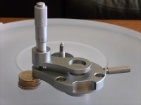
So, I went ahead and swapped the HD560S 120Ohm drivers with the 50Ohm drivers from one of my HD599 pairs.
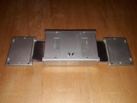
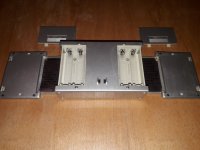
You just unscrew the baffles from both pairs, desolder the drivers and then solder and screw the HD599 ones in the HD560S housing.
NOTE: You can use the HD559 as a 'donor'. They're using the exact drivers/baffles.

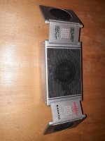
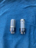
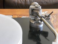
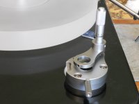
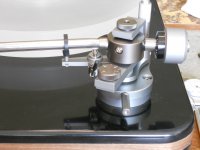
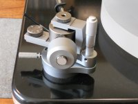
Here you see the HD5699 'hybrid'!
20220722_111217.jpg
Basically it looks like a typical HD560S.
Until you put them on and notice that something HAS audibly changed.
---------

From here on I attest my personal opinion (and rant), so please bare with me:

The 'HD5699' doesn't sound 'sterile' and/or flat anymore..

HD560S, while it's measuring good, I think it lacks body and impact. It has soundstage and is not grainy, I'll give it that.
But some important parameters for real music enjoyment, namely body, pace and impact, were missing.
When you create a headphone simply to look good on papers, based on whatever current 'target response', you might end up with a 'flat' sounding pair.

Sorry Sennheiser but this is still an HD5xx series headphone and folks enjoy them for their laid-back, full-bodied character that gives life to music.
For uber-technical 'neutrality' and 'follow the graphs' orthodoxy, there are myriads of other models out there. I have an HD600 for that I think..

My point is, who cares if it measures great but it hurts your ears after 10 minutes, or you need a graphic equalizer to enjoy music?
-End of rant-
-----------

How does this 'hybrid' sound?
In a nutshell, a bit better than the good old HD599.

Probably due to the slightly different shell of the HD560S (wider grill holes and no plastic overlay).
It gives more focus and impact to the sound.

Lows are better articulated and go deeper, mids keep their presence but are better controlled and highs become less grainy.
Soundstage increased a bit, both in width and in height.
Separation of instruments and sense of depth also improved.

Maybe, it has to do with reduced resonances resulting in better driver control?
I don't know, but the result is good (to my ears at least). 🙂

So folks, if you enjoy the sound of your HD599/598 but feel your HD560S falls short of your expectations, you might want to give the 'HD5699' a try.
You can always revert back to stock, if you are not impressed.

Have fun and thanks for reading!

Bose AM5 series 1 modification

Bose_Acoustimass_5_Series_1.jpg
I know, I know, not worth it...
But, it is very easy and cheap to do.
Original crossover schematic reveals parallel RLC circuit in unsuccessful attempt to linearize the frequency response of the double-cube satellite. The first low value resistor actually is a lamp for protection. Two 33 microF capacitors, for total of 66 microF, are the high-pass filter for the satellite.
Bose AM5 Series 1 XOver.png
It can be done much better, with different values of R, L and C. I wanted to replace both inductors (L=0.31 mH) but they were glued with excessive amount of gooey glue and were impossible to remove, so I left them. I replaced 15 microF capacitor with 6.8 microF and 3.3 ohm resistor with 10 ohm. Much better - see the measured on-axis frequency response of the dual-cube satellite before (red) and after the modification (green).
Bose AM5 Series 1 SPL.png
Frequency response at 30 degrees horizontal is in blue (after the modification). Not bad!
Bose AM5 Series 1_hor_30 deg.png
Forget about the direct/reflecting marketing trick, just aim both cubes straight in the room.
As you can see, satellites go down below 300 Hz. Subwoofer go down above 160 Hz, so there is some 6 dB dip in between, centered at about 210 Hz.

VTA on the fly for Jelco tonearms

Saw this on Audiogon and decided to try one for my Jelco 750E (I believe they make them for other models/mfrs). Well built, very smooth and with the thumbscrew tightened down, rock solid. Makes very precise adjustments a snap and there is no backlash in the adjustment like other systems. The adjustment plunger appears to be from a micrometer. $200.

Purus Audio Cables

Not affiliated with the mfr, just a satisfied customer.

Before and after shots attached.

Attachments

  • DSCN1595.JPG
    DSCN1595.JPG
    256.9 KB · Views: 870
  • DSCN1596.JPG
    DSCN1596.JPG
    254.5 KB · Views: 855
  • DSCN1597.JPG
    DSCN1597.JPG
    256.4 KB · Views: 880
  • DSCN1598.JPG
    DSCN1598.JPG
    252.7 KB · Views: 1,000
  • DSCN1599.JPG
    DSCN1599.JPG
    253.5 KB · Views: 915
  • DSCN1600.JPG
    DSCN1600.JPG
    254.8 KB · Views: 571
  • DSCN1601.JPG
    DSCN1601.JPG
    253.3 KB · Views: 566
  • DSCN1602.JPG
    DSCN1602.JPG
    257.7 KB · Views: 689

What is a good 11.2896 MHz oscillator / crystal for es9023 DAC?

Hi

I have never purchased an oscillator / clock / crystal and any assistance would be greatly appreciated. I need to replace a 50mhz oscillator with 11.2896mhz on an es9023 DAC. I would like to use something with low jitter/high performance but not over priced.

My DAC is a basic es9023 the same as this; AUDIOPHONICS I-Sabre LTE DAC ES9023 Raspberry Pi A+ B+ 2.0 /3.0 I2S - Audiophonics

It has a universal footprint for oscillator placement.

What would you suggest??

Reasons for replacing:
I wish to connect to a Wiimu/Linkplay A31 media streamer module. The A31 operates in slave mode requiring LRLCK and BCLK. It however will only send data via 44.1khz 256 (16 bit; bit clock 2.8224 MHz). The es9023 data sheet which has very little information indicates I would need a clock of 11.2896 MHz.
Similarly, the A31 has been adapted to the ADAU1401 by replacing the oscillator with a 11.2896 MHz however I wish to use my es9023 DAC; I assume it will work?
Wiimu A31 module in combination with ADAU1401/1701 DSP
20141004215048554855.jpg

What to do with a Mitsubishi LT20

Hey everyone,

Simple question I think. I acquired a super clean Mitsubishi LT20 turntable for free that mostly works - tonearm stops moving halfway across the record.

My question is whether I should keep this or sell it, and if I sell it, what might it's value be? I have a Project Debut Carbon currently and want to upgrade to something in the $1000-1500 range. Is this Mitsu LT20 comparable to something like that? I hear a lot about how nice it is, but honestly, listening to the first track on a few records it sounds unexciting unless more is wrong with it.

Thanks and hope ya all have a great day!

A little help on this crossover

First time using Xsim.

Bookshelf = Woofer (60W) + Tweeter (25W). (ignore Sony label)
bookshelf.jpg

Sub = 2 x 120W (philips SW8100P/37 - ordinary and very cheap)
sub.jpg

Weird LC values...but the final response seems (reasonably) flat.

EDIT : I'm doing a 3-way passive filter now (for the sake of completeness)

Files :

ZMA and FRD files

Crossover :

crossover.jpg


Freq Response (Woofer / Tweeter / Sub) :

Woofer SL-651R Curve 1.png
Tweeter curve 1 (similar).png
sub_1.jpg

SIT THF51S with Output Transformer. Any ideas, experiences?

Hello All,
I am interested in gathering information about building an amplifier that uses a sit like THF51S as its final device with an output transformer like Hiraga's Nemesis or Susan Parker's Zeus. The output transformer would also make it easier to adopt a working point other than the usual low voltage / high current. Probably the THF51S at 250volt and 300 / 400ma is more linear than the usual working points and could be an alternative to an SE of 845 or 211 with the advantage of only needing 10 / 15volt of signal (against the 160volt of the 845 or the 60volt of the 211) In my case this amplifier would work in a multi-way system where it would drive the mid-bass horn from 100 to 700Hz, so it would be easier to build the output transformer by limiting the response at the bottom.
Any suggestions?

Giveaway - SJEP120R100 pair

While we’re all waiting in anticipation for the next vfet amp, I thought it would be fun to give away a pair of some other unobtainium - ye olde Semisouth jfets. Some time ago I was the recipient of a completely unexpected, unearned gift of four SJEP120R100 from a very kind and generous guy that some of you may know. Anyways, I’ve been having my fun with them and have come to the conclusion that I’m completely happy with just a pair of these. So I thought I would extend the generosity and pass this extra pair to someone else in the Pass forum who hasn’t had the opportunity to play with them.

Rules
  • - if you don’t currently own any SJEP (DIY or production amp) you’re eligible
  • - I’ll cover shipping within reason. If you’re in some remote corner of the world and shipping exceeds, say $10 USD, I may ask you to help cover the rest
  • - These parts are used, but work just fine. If for some reason they arrive and were damaged in transit, that’s too bad - I don’t have another pair to give you.
  • - I’ll keep entry open until 8pm EST tonight (10 March, 2021) From there, I’ll take the last post that contains all entrant names, randomize with random.org, and the person at the top spot will be the winner. I’ll post the screenshot - it’ll be winners responsibility to pm me with their shipping info.

To enter just copy the previous post with entrants names, add yours, and make a new post.

Attachments

  • 1541E4A1-01DB-40B9-A3D7-011660442445.jpeg
    1541E4A1-01DB-40B9-A3D7-011660442445.jpeg
    425.3 KB · Views: 1,308

G'day from ChrisCables in NL! ;)

Hi from a very warm little workshop at the top of my house in the Peoples Republic of Vleuten in the Netherlands!

I thought it was about time I registered an account after lurking for a while, so here I am!

Been making my own interconnect, speaker and headphone cables for around 30 years now, as well as collecting bits and pieces of hifi, headphones and Walkmans. Big Nakamichi fan and have a nice little clutch of tapedecks including a Dragon, RX202 and CR4E.

I'm a headphone guy at heart and so tinkering with headphone cables and finding nice matches between different compositions, geometries and types of cables and headphones has been enormously interesting to undertake. So much so that it is currently my 'paid hobby' building cables for others. Hoping to go commercial at some point in the near future and maybe segue into a fulltime career with it!

But for now, hoping to share info, stories, tips, tricks and experience with other like-minded souls on this great forum!

A few of my creations....

01_1.JPG
04_1.JPG
05_1.jpg
06_1.JPG
07_1.JPG
11_1.jpg
17_1.JPG
bert_013_1.jpg
DSC_0013_1.JPG
  • Like
Reactions: evonimos

passive membrane vs passive radiator

hi everyone, i was wondering if there is any sound difference in the passive membranes mostly used in portable speakers and passive radiators ( passive speakers with spider etc.), wich 99% of the time are used in the DIY community. the passive radiators seem to have better control because of the surround AND spider but is this really important or is this just a minor thing. passive radiators have a mass (added) limitation and are not that flat while a passive membrame can hold more (moving!) mass because the weight is more distributed over the piston erea instead of a heavy loaded spider wich can become uncontrolable( like a camper behind your car wich goes out of balance on the highway) and is way more flatter( so less space ).

Custom Build Mixing Console

Hi guys,

As I always dreamed about building my own custom mixing desk we decided to start building one. I know it's more oriented to studio etc but here it goes. We started this around a year ago. For the basic preamp we use the neve 1084 design. We like the sound of this preamp and have good experience with building this preamp. We then devised a way to make Inline modules based on the 1084 and also added a balanced insert point. There is ofcourse a lot more to it then this.

The power supply is 3phase Full wave rectification. This way it will have low ripple and the buffer capacitors will have an easy life and will last long. A neve 1084/1073 wants a good power supply. The concept of this console is also to build something that will last and if something happens the session can continue and it can easily be fixed. The raw rectified power supply is then split up in 4 seperate lines. In the console are the smaller power supplies using lm317/lm337. there is one small power supply for each pair of channels. So if something fails the rest will keep on going.

Then the VU meters are set to 8dbu=0VU. Normally this should be 4dbu = 0VU but for some reason today's engineer like to record quite hot.....don't know why you would do that when you have 24bit adc....... but ok. Doing this we avoid that the meters are continuously pegged to the right....

So now some pictures:

first things first and we started out with a small frame prototyping.
test1.jpg


After this was tested and checked, the work started on the frame.

An externally hosted image should be here but it was not working when we last tested it.


And after some more work:
An externally hosted image should be here but it was not working when we last tested it.


the work also started on the soldering some PCB's....

preamp.jpg


EQ.jpg


Elma Switches for the gain switch
elma.jpg


P&G faders


pgfader.jpg


after the channelfronts have arrived:
channelfronts.jpg


after the Faderpanels have arrived:
faderprints.jpg


The inside of 1 channel module:

inside.jpg


inside2.jpg


the power supply build:
ps1.jpg


ps2.jpg


Last update untill now.
total1.jpg


VU.jpg


faderknobs.jpg


I have more photo's but this will do for now. I will add more as progress goes.
  • Like
Reactions: adason

For Sale JVC RC-EZ31 donor parts for Shigaclone

Hello,

I have these parts coming from a JVC RC-EZ31 boombox for sale:
- The transport
- The control board
- The remote control
- The puck (which sits on top of the CD)

These parts have been removed (unscrewed) from a JVC RC-EZ31 boombox several years ago, but I never built it.
There has been no soldering or modifications done to the parts whatsoever.

Asking $150 + shipping.

Attachments

  • PXL_20220822_211925198.jpg
    PXL_20220822_211925198.jpg
    711.4 KB · Views: 222
Projects by fanatics, for fanatics
Get answers and advice for everyone wanting to learn the art of audio.
Join the Community
507,726
Members
7,885,945
Messages

Filter

Forum Statistics

Threads
406,125
Messages
7,885,945
Members
507,726
Latest member
analog_audio