Transnova-Schade OS/Amp

Here is a nice and long-known circuit, (Jim Strickland's Transnova) with Schade feedback added (see the plot of the output characteristic in the attachment), transforming it into triode-like push pull output stage (or stand-alone amplifier with voltage and current gain).

What's nice about it:
- Great PSRR. Thanks to symmetrical topology the ripple waves from both rails cancel each other so when nicely balanced (no DC offset on the load) there is no noise on the output. Totally black background. No RC/LC filtering is needed (they actually make the situation worse - I put the 0R1 resistors in the rails just to check the current easier). Good and ample filtering capacity is all you need (with +/- 20V rails, at about 60,000 uF total per channel is when the low of diminishing returns starts to kick in).
- easy to work with. Lateral MOSFETs have Source on their body so mica or similar insulation is not needed, just connect heatsinks to GND. They also need no degenerative source resistors here, therefore enabling the square law mode i.e. extended class A current regime) and there are no thermal worries too - no temperature compensation is needed.
- High voltage swing, unclipped output is about 36Vpp on +/-20V PSU.
- Very fast and stable - see the 20 kHz square wave at the output with 5R load. Adding a 1uF in parallel to the load just makes the lines straighter with no ringing. I tested output level up to 95 kHz and it doesn't drop.
- Power supply rails are floating and each channel needs its own transformer with two identical secondaries so whether you want it or not you'll have dual mono amp. 🙂
- Clean, detailed and lively sound - no muddiness or harshness with complex orchestral music.

What's not so nice:
- Relatively high Zout - changing the load from 5 Ohms to 2.5 Ohms brings the Vout from 6.4 V to 4.5 V . It's not a problem if your speakers have high (8 or 16 Ohms) and steady (doesn't change a lot with frequency) impedance module. If not, you can encompass it into feedback loop with preferred gain stage or change your speakers... 🙂
- Relatively low Zin - as drawn it is about 1k (R1 || R4). R5 is there just for GND reference. Zin can be higher but at the cost of the bandwidth. In spite of that a lot of good preamps/gain stages will happily drive it: BA-3, LSK preamp, a lot of good OpAmps (AD829, AD797, to mention some).

How it works (attached schematic shows the test bed):
we see a complementary pair of Lateral MOSFETs, their Sources connected to GND and their Drains are AC-wise (through PSU caps) connected to each other, and load is connected between the Drains and the GND which makes it a push pull common source stage, giving voltage and current gain.
MOSFETs are biased through voltage dividers (R3+R2/R1 for Q1 and R6+R7/R4 for Q2). R2/R1 and R6/R4 relation is a local Schade feedback ratio and it sets the gain (R1 must equal R4 and R2 must equal R6 or you'll be introducing 2nd harmonic distortion). You can make this ratio higher or lower, depending on your preferences but you must have in mind that the bias current will need a new setting too.
R3 || C2 and R7 || C3 are DC shifters that enable us to separate biasing from gain settings (caps are short circuit for AC signal). As it is drawn, the bias current in real circuit is about 460 mA and DC offset at the load is 9 mV.
To adjust it at will change R3 and R7 into serially connected 15k resistor and 10k or 20k pot so you can finely adjust it to preferred bias current and 0V DC offset at the output (pretty much as described in F5 article - start with the max pot value i.e. minimum Vgs). There's not much point in biasing it to class AB although it will work...
Using a different rail voltage is OK, you just have to calculate your R3, R7 values anew (google: voltage divider calculator).
To increase the Zin, make R1 and R4 higher value but you'll have to change R2 and R6 accordingly (to keep the same gain ratio) and R3, R7 too (to keep the same bias current). Don't go too high with R1, R4 because it will lower the bandwidth (RC pole with MOSFETs' parasitic capacitance)

As you can see, the circuit is simple and rewarding. It opens a lot of space for experimenting and is highly accommodating to broad spectrum of applications.
Have fun with it...

P.S. If you still haven't grown out of "capacitor-in-the-signal-path" phase, this thread is not for you. 🙂

Attachments

  • tsdc.gif
    tsdc.gif
    24.3 KB · Views: 2,721
  • tssch.gif
    tssch.gif
    12.8 KB · Views: 2,811
  • tst.jpg
    tst.jpg
    111.9 KB · Views: 2,786
  • tsm1.jpg
    tsm1.jpg
    87.2 KB · Views: 2,389
  • Like
Reactions: mterbekke

LM1875 SPICE Model and DC-Offset adjust

LM3875 and LM3886 are very hard to find and buy.
LM1875 is however around in plenty.
So. let us use LM1875 to build good sounding chip amps.

I have the LM1875 SPICE Model.
You can download it from here: https://www.ti.com/product/LM1875?keyMatch=LM1875#design-development

In my attached image I use the potentiometer R5 to adjust for DC-Offset.
It is nice to have close to zero on the output.

Attachments

  • LM1875_image1.jpg
    LM1875_image1.jpg
    30.2 KB · Views: 404
  • Like
Reactions: NanoFarad

Mosfet replacements for Mordaunt Short ms909w sub amp

Hi, unfortunately, all the labels on these MOSFETs appear to have been scratched off 🙁
Does anyone know of correct/suitable replacements for this model?
It's a 300w amp with "Digital subwoofer ds-300" stamped on the back of the PCB.

An externally hosted image should be here but it was not working when we last tested it.

An externally hosted image should be here but it was not working when we last tested it.


Big pics here:
https://1drv.ms/f/s!AhEaoM8TIFO4niEpBhk_KlwxRhOZ

Thanks in advance for any help

FS: Distractions (clone) bookshelf speakers

These diy builds were made a couple of years ago, based on the Distractions that were well received in this link:
https://sites.google.com/site/secdiyaudio/2012-event/winners-and-awards
I already had built the solid red oak 0.5cuft. cabinets with leather covered sculpted baffles from a previous project and
adapted them to build the Distractions but using Peerless 0.75 dome tweeters in lieu of the rather expensive Hiquphon OW1.
The best stand mount speaker that I have built.
Peerless 6.5” nomex woofer. crossover as original.
$200 including shipping to Conus.

Attachments

  • 9548A1E8-BFA6-4C55-90FA-02C076B768F6.jpeg
    9548A1E8-BFA6-4C55-90FA-02C076B768F6.jpeg
    234.4 KB · Views: 164
  • 47D03162-BCA7-4D9C-AABF-FAB6BD3172B1.jpeg
    47D03162-BCA7-4D9C-AABF-FAB6BD3172B1.jpeg
    284.7 KB · Views: 164

if building for this driver:

what do you think would be the ideal cross-sectional area for these four drivers? The plan is to get it into an ODMLTL enclosure that looks like the drawing/sketch up (with 4 drivers?)

I need enough room to fit the drivers this way, but the Vas in these car audio drivers wants to be kind of small and sort of making it difficult??

if playing with the SIM is there a comfortable CSa that you would recommend that’s bigger or smaller( or whatever) you feel is ‘best’? what I have there is an example can be looked at in the wizard as the Upper section will be lined with open cell foam in a decent thickness as well as layers of poly filled required to knock down the endpoints of the bandwidth which at the bottom are kind of curly as you might notice???

Wood is too expensive and I simply don’t feel confident doing anything right now without calling in the voice of collective reason(diy audio). ( third generation Toyota four Runner SUV, btw)

Attachments

  • 3B8D3C27-F99B-498B-AFB3-D53863E4D6B6.jpeg
    3B8D3C27-F99B-498B-AFB3-D53863E4D6B6.jpeg
    112 KB · Views: 151
  • image.jpg
    image.jpg
    529.1 KB · Views: 162

SAE D102 - Reverse engineering LED display module

The Corona pandemic gives me reason to stay indoors and burn up some brain cells trying to fix a problem which seems to plague a lot of SAE CD Players. Often the digital display will lose segments or go completely dead. Unfortunately the display is not just simple 7 segment LED's. It is a complex self contained unit that communicates serially with the main board. When it goes bad it is not really repairable. The chip on it looks like a glob of glue. This part is unobtanium. I have tried to negotiate research with the manufacturer and they tell me it is too old to research.

The SAE D102 is based on a Phillips/Magnavox chassis. The Phillips/Mag players tend to exhibit similar problems and use Green LEDs instead of Red. I was inspired when I saw that someone in the Netherlands had reverse engineered the display module for a Phillips unit. I actually tried to contact that person but my questions failed to get a response. I can understand when people don't want to share their hard work so I decided to reverse engineer the SAE display module on my own. The SAE variant is a little different. It has more pins (12 instead of 9 or 10) and addresses all 35 display bits to not only update four 7-Segment LED's but also drive 5 other stand-alone LED's such as Pause, Error, Index, Time and Repeat.

I made some progress this evening. In the photo you can see that I have at least two of the four 7-Segment LED's working on some mock-up jumbo LED modules. Once you solve the equation for 2 digits the others are easy to figure out.

attachment.php


The second photo shows the original module from @ 1987. Below the module are the new IC and 7-Segment LEDs that will replace it. I have to finish drawing the printed circuit board in CAD and then I will get a number of PCB's printed up for formal testing. It will be a long process but time is in abundance lately!

attachment.php

Attachments

  • 20200417_214138.jpg
    20200417_214138.jpg
    638.2 KB · Views: 1,257
  • 20200417_213937.jpg
    20200417_213937.jpg
    614.3 KB · Views: 1,221

Diamante -a discrete medium power opamp

Hello and happy New Year!

I wanted to post something for the forum on the first day of 2008 in the hope that we all have happy and enjoyable new year, and hopefully some of you can use it in your audio pursuits.

I have designed a discrete operational amp/headphone amp I have named "Diamante" mostly because it has a diamond buffer type output stage.

The design is pretty simple and not at all expensive to build. The cost/performance ratio is very high. The prototype was made with all BC550 and BC560 transistors but others with the same pin configuration can also be used. I chose BC550/BC560 because of their low noise and high gain. Many transistors have reverse pin configurations and they can also be used but you will need to put them in reversed of course.

The basic schematic as shown is configured as a 6db voltage gain headphone amp. But you can configure the board any way you like. The amp is unity gain stable with 10pf at C5. Choose RF and RG so as not to overly load the output stage.

The output R (R26) is a 3W type with magnet wire wrapped around it (15-20 turns is fine) to form an output inductor. This will prevent ringing into capacitive loads, but it is not required. The amp is stable without it. if you wish to omit it you can jumper it with wire or take your output at the resistor pad.

Rbias sets the bias for all stages. I should be a 1K pot, when initially setting up the amp set it to full 1K resistance. Then slowly adjust it downward until you get about 25mv across the emitter resistors (R1-R6). This is a safe bias point.

Once you have the bias properly set, then adjust Roffset to get 0V offset from output to GND.

Wait around 5 minutes and re-check bias and offset.

This amp is pretty simple to scale. As it is presented it should be about to do 100ma or so without much problem. If you change the output devices you could get even more output.

It drives headphones with ease and that's really the purpose I had in mind. I will easily drive even 32ohm cans. 300ohm types such as HD650s are cake for this amp.

Noise floor is very low with the transistors specified. I can't hear any noise through the cans - nada.

Distortion is very very low, though I don't have any pretty graphs to show you yet.

So happy new year to all. I am providing PDFs and the Schematic for those who want to etch boards for DIY use only. The amp can actually be built pretty easily on prototyping board too.

Here is a picture of a prototype (slightly different CCS) in use. Special thanks to Brian Donegan who etched stuffed the first boards and encouraged me to finish the project.

Cheers!
Russ

Attachments

  • ha1 012.jpg
    ha1 012.jpg
    95.1 KB · Views: 8,217

Is a Parasound HCA-2200ii still reliable?

I have the opportunity to get a Parasound HCA 2200ii but won't have the chance to listen to it first. I love vintage gear so this doesnt seem very old to me, but doing research it seems like most threads are about some kind of problem.

I would be replacing a Yamaha MX600 which has ran flawlessly. I know anything can have the potential to have problems, but some products are prone to it and some are not.

Thoughts? Experiences? Are there certain things that always go bad on this amp that I should just expect to fix?

Thanks!

After 10 days of planning and 2 days of building; thanks to one forum member / an OB

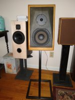
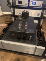
After 10 days of planning and 2 days of building: an OB

With about 365 times less procrastination than last time After a decade of planning, thanks to forum members after reading The 'Circles of Doom'.....Open baffleless full range speakers. I thought - it’s about 14 years since I’ve tried OB, so…

My goal was to use drivers I could get my hands on within a week or so and build something easy.

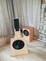
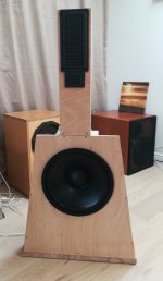
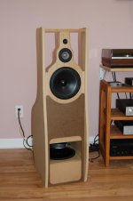
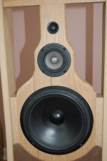
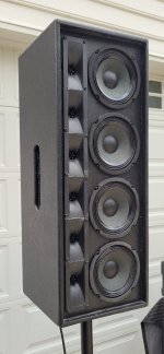
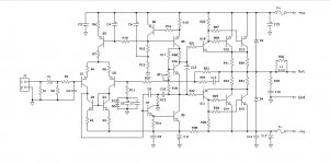
The Neo3 and Neo10 happened to be available and are irresistible. I did some simulations and decided to use the Neo3 on its “side”, underneath the latter, with minimal gap aiming for (and it turns out achieving) a 3kHz LR24 crossover. The baffle is routed out behind and flat in front. A quick test baffle showed this is fine, with baffle effects on the Neo3 significantly below the crossover (I had wondered about scalloping out the wood either side of the Neo3 but decided not to).

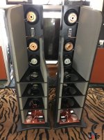
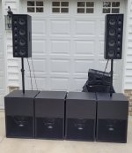
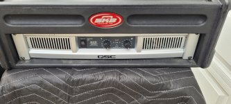
I’ve got four subwoofers of three types and decided to use those up to ~90Hz. This decision is based on room modes and consideration of the location that the new speakers would have to occupy, to be far enough from walls.

The aim was to use an LR24 crossover around 700Hz from the Neo10 to an OB base driver with proportionately larger spacing (it’s 660mm c2c, and the crossover is a little under 700 Hz). The lower baffle is mildly U-shaped, with tapered rear “wings” mainly for bracing. I wanted to keep the base width no more than 2’ or 61cm.

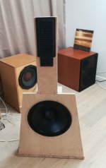
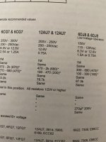
After looking at easily available bass drives of trustworthy/known quality, I chose the B&C 14NDL76 as a cautious compromise. A 15” would also fit in the tapering baffle at the desired height, but I knew that the 14NDL76 has a smooth response and would give some margin to adjust the crossover upwards if I had trouble with the low end of the Neo 10 (no sign of that, however).

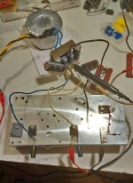
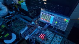
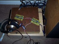
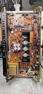
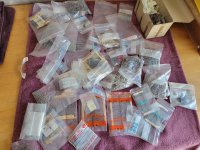
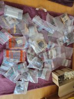
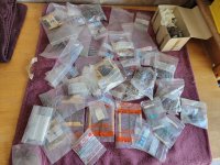
The drivers arrived promptly, and it took about 8 hours to build the speakers in two sessions split by varnish drying overnight, an hour to burn-in the bass drives, and an hour or so to wire, test and set up the EQ. I only have limited hand tools and very limited skill, which none-the-less proved sufficient (a nice new saw, electric drill/screwdriver, electric jigsaw with thin blade, files, sandpaper, and a router with round-over bit for the back of the upper baffle).

The baffles have some added stiffening strips, as well as the wings on the lower part; these taper from ~1cm at the top to ~10cm at the bottom. The lower baffles are fixed on to iroko butcher block off-cuts from earlier speakers and are ideal to add mass and make a stable platform.

The whole speaker sits on compliant, damped feet, to give a ~10Hz low-Q rocking resonance. The connections between the upper and lower baffles are also compliant and damped (metal flexures and damping). This connection was tuned to avoid resonances of the lower baffle and I cannot feel vibrations of the lower baffle on the upper – the rocking mode is about 40Hz. The upper baffle could benefit from some more damping or stiffening in its lower part, but the radiating area is small and the resonances are not conspicuous with a microphone placed nearby below the tweeter – more investigation of this later.

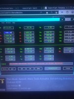
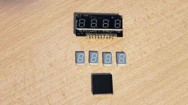
The Neo3s required EQ to achieve a flat response, as expected. That done, they blended almost ideally with the Neo10 (30dB tweeter-axis, reverse null with symmetrical LR24). The Neo10s only required a small boost below the lower crossover frequency to blend nicely with the 14NDL76 with LR24. The bass required some boost (4dB 90Hz Q=0.8), and I put a mild notch at 2kHz (-4dB Q=4), though not really needed. The response is generally smoother than the B&C datasheet suggests, but the trends are accurate.

As the speakers were only finished a few hours ago, I haven’t fully dialled in the four subs – only roughly: good enough to be enjoying music. Though I gave the 14NDL76s some LF work for an hour, their suspensions will possibly soften up a little more and I’ll revisit the bass-EQ again in a week or so.

The Neo10s measured almost identically, as did the 14NDL76s. The Neo3s differed by up to 1dB in a band around 10 kHz – whether this is from the drivers or due to small differences in the way I mounted them is unclear. I plan some front/rear measurements that might give a clue (sometime).

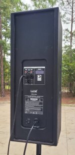
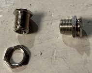
I used push-on connectors for the Neos, and the B&C drives came with spring connectors.
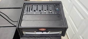
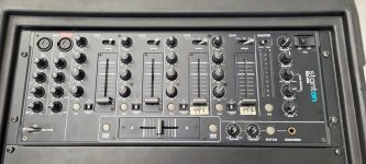
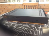
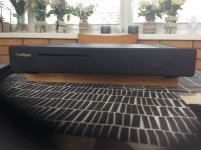
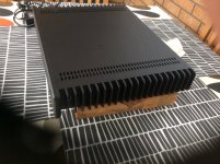
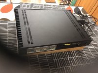
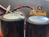
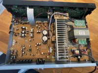
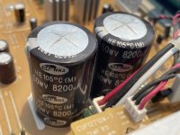
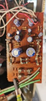
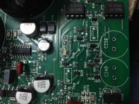
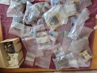
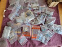
I hope the photos give the rough idea.

Editing to point to the main changes and discoveries since writing the above.

Improved understanding of early reflections, and the benefits of dipoles in this regard - mentioned at various places, mainly around #90. I could write more on this, as it's one of the most important considerations for choosing hifi speakers in a small room.

The first 44 posts describe the development and testing of the speakers with DCX2496 filters. The change to Hypex FA123 is described here: https://www.diyaudio.com/community/...to-one-forum-member-an-ob.374532/post-6801982
Although not fundamentally different, the extra DSP flexibility has allowed finer tuning in a few minor areas.

DRC was introduced https://www.diyaudio.com/community/...to-one-forum-member-an-ob.374532/post-6802001

Having good control of early reflections by design and positioning of speakers makes it easier to figure out how to best use (gentle) DRC for speaker and room correction in different regions of time-frequency space. I have a much better appreciation of how Toole & Olive and Bech et al findings fit together allowing proper consideration of early reflections. To communicate this in full would take many words - only the gist is in the thread.

Moving the bass-mid crossover down to ~400Hz (hence one lobe) came late, and only led to good outcomes: https://www.diyaudio.com/community/...to-one-forum-member-an-ob.374532/post-6888697
this extent of the change caught me by surprise (even setting aside the error during the comparison with the higher crossover (see #87) - the error did lead to a lot of interesting comments.

Thanks again to everyone who commented and contributed along the way. The project is now complete and I don't plan to add posts, unless interesting questions come up.

Ken

Attachments

  • olla.jpg
    olla.jpg
    495 KB · Views: 1,312
  • obra.jpg
    obra.jpg
    126.5 KB · Views: 1,318
  • obrb.jpg
    obrb.jpg
    134.5 KB · Views: 1,480

BRIICe XO topology

Note: moved from https://www.diyaudio.com/community/threads/crossover-design-help.389659/

Hello, I am planning on making a 3 way crossover for a tweeter, mid woofer, and woofer. I have imported all the FRD and ZMA into xsim and designed a crossover. i am very new and was wondering if anyone could see if this looks good. Thanks!
View attachment 1084766View attachment 1084768

May we suggest not using any traditional cross-over circuits.
Cross-over circuits have been an incorrect process since the 1930's...


BRIICE - 1.jpg
Phase - Power  web - 2.jpg
Era Sensitivty Graph - 3.jpg
CKTs T M W web - 4.jpg

Old speakers without references need new tweeters

hi guys,
I think I put my fingers into something I can't handle. I've been lurking for a while, without finding answers. I was about to proceed by trial and error but I guess I should first ask Internet...

tldr: I've no data, and I need to choose a new pair of tweeter

I found some old 3 ways speakers (25yo? ~90x60x40cm h/w/d, ported box woofer, enclosed mids and tweets) hand made by a dead company. (I wanted to quickly restore them for an association I'm part of). But one of the tweeter is missing, so I would need to replace both of them. Sadly besides being able to measure that they are having 8ohms of resistance, I've no rating. They are numbers on the back of the speakers but they look like old serial numbers and internet couldn't help me (tweet: 4988 and 8B on the basket, mid: 5293/5, woofer: 4986/1 and 7M on the basket). I work in electronics but not so much with this kind of stuffs. I wrapped my head around that with my colleague and we concluded that we could only get a a guess at the last original tweet wattage by blowing it, but this won't give us anything about sensitivity in order to have a kinda balanced speaker...
I'm currently working on the filters (some weld "dried", not sure of the proper English word sorry, and I'm waiting new potentiates because one of them burned badly). But from then on, I'm helpless.

Would there be any advice on how to proceed? Would there be another way then trial and error (even if it's just an estimation)? Anything I can mesure to help me take an educated guess (something on the old tweet I still have, the size of the tweet enclosure? mesuring the watt drawing difference between the speaker with or without the tweet, idk...)
If I can't find anything, what would be a safe option? should I look for a tweet with high wattage low sensitivity to be sure to not blow it?

Thanks a lot for any help!
(if it is of any help, I can upload pics of the speakers and their parts)

6ha5

Folks,

Has anyone ever used a seven pin, sub-miniature 6HA5? I have four I'd love to try out; 1963 tube, GE, branded 'Sears'.

This tube is a 14.5mA/V, mu 72 12mA single triode for use in VHF as a grounded grid amplifier. Plate dissipation is 2.6W.

Anyone know what the sonics are?

Cheers,

Hugh

Send Cut Send - laser cutting

Some of you might be interested in this laser cutting service I recently used.

Laser-cut metal parts Shipped Fast | Instant Quotes

No affiliation or anything and their prices are really good. Upload a dxf file and you get an instant quote based on the thickness and material. I had four of these little adapter plates cut to use 9 pin sockets in chassis cutouts made for 9 pin magnoval sockets. Total for all four cut from titanium was $39 shipped!

Definitely going to use them for making my next chassis.

Attachments

  • IMG-1524.jpg
    IMG-1524.jpg
    470.3 KB · Views: 701

Hobbyist (read: cheap) CNC/Laser Cutting

Hello,

Long story short, I'd like to make a few revisions of things without breaking the bank. I ordered a CNC cut rear panel from DIY Audio store for my 3u slimline chassis. It turned out great and I think they did an excellent job- very much worth the money... if you only have to do it once. While what I have will work, moving some holes a few mm would make it that much better. I'd like another stab or two on the CNC mill!

However, paying $78+ shipping every time for a 120x435x3mm piece of aluminum hurts....

I have went through many online CNC quotes and I don't know if they only serve NASA because their prices are all ridiculous. I'm talking double the price previously mentioned for an unfinished piece of 6061 aluminum, plus shipping! Is there no service out there for small time hobbyists like you and I? Will DIY Audio offer me a 'noob' discount for trying again? I'm not sure, but I may email them.

Thanks friends

Looking for 6P30B Amp Schematic

Hello, everyone. I have recently joined this forum in pursuit to build a sub mini tube amplifier for my home setup. I have built quite a few circuits since I've started DIY electronics a few years back and would really like to get this one done. I had finally decided to purchase a turn table to play some records I had been given years ago and of course I was not prepared lacking a preamp and an amp/receiver to power a pair of speakers.

A couple years back I've purchased a bunch of 6N16B and 6N17B triodes and also a handful of 6P30B pentodes. Since I'm not a conditioned or savvy electrical engineer I am hoping someone around the forum may have an amplifier circuit that uses these tubes they could send my way.

I have chosen this forum due to the popularity of turntable topics. I have also found here the Mini-Me Preamp that uses 6N16B tubes and I am for sure going to use this for the MM RIAA preamp. I believe what would come next is a stereo amplifier with a a few preamp controls (ya know, like a guitar amp but not as noisy).

To note; my experiences have been with stompboxes, synths and one tube amp under my belt (deluxe reverb).

EDIT: this being my first post I may have put it in the wrong subject of the site. My apologies. EDIT AGAIN; looks like it was moved. Thank you 😀

Newbie needs advice: Chance to buy JBL LX44 or PSB Stratus Bronze. Which would you choose?

Hello,

I'm planning on restoring an old 50's RCA tube stereo and have the opportunity to buy these speakers to use with it. I'm not sure if the choice is dependent on the amplifier but which do you think is a better speaker? The JBLs are a proper 3-way and the PSBs have the "2 1/2 way" double mid range design.

Thanks for any and all comments.

SpeakerFest 2022, Saturday August 27th, 10am-4pm, Fountain Hills Community Center

Here is your chance to hear the DIY XL-S Encore with XO upgrades.
Or the DIY Falcon Acoustics Q-7

Saturday only 10am -4pm. Come to Fountain Hills Community Center 13001 N. La Montana Dr,
Fountain Hills, Arizona 85268 to audition 17 different, highly acclaimed speakers.

Details on AZAVCLUB.com All Standmounts. MSRP $650-$2,900.

GiveAway- A pair of Elac Unifi Reference UBR62 MSRP $1,200

Show Prices on New LSA 80-(World debut!) $900/pair. Buchardts $1,700.
Used-Tekton Monitors $1,100, Totem Sky $1,400

Show day giveaways from Parasound and Straightwire

Meet Leo A. of Orchard Audio demoing his latest amps. Dennis Murphy and his Philharmonics!!
Reps from KLH, ATC, SpeakerLab, Parasound, Straightwire also available for consultation.

Specially curated music of the best recordings!!

Best Saturday you will have had in a long time!!

Attachments

  • COMMUNITY CENTER 2021 layout.pdf
    COMMUNITY CENTER 2021 layout.pdf
    121.6 KB · Views: 86
  • SpeakerFest Flyer - p2-3.jpg
    SpeakerFest Flyer - p2-3.jpg
    479.4 KB · Views: 170
  • SpeakerFest Flyer - p1-3.jpg
    SpeakerFest Flyer - p1-3.jpg
    456.5 KB · Views: 160
  • Like
Reactions: Pano

Calculating Open Baffle lengths

Hello all. I have a question. I am wondering how to calculate the dimensions of an open baffle speaker. The speaker I have in mind is somewhat similar to Danny Richie's NX Otica, but I struggle to understand a few parts of his cabinet design. Particularly, the asymmetry of the side wings for the mid/hi section. I understand the purpose of these wings to be to help lower the cancellation frequency band, but I do not understand why the NX-Otica speaker has taken half of one of the wings and chopped off a huge section.

Is it to help reduce cavity resonance, and if so, how do you know how to calculate how much of the wings to chop off? I see that for the bass section of the speaker, the NX-Otica does not have tapered wings. Should I take this to mean that whatever issue this practice corrects is not presence in the bass section of an open baffle?

If the reason for this is cavity resonance, is cavity resonance not something I have to worry about as much in the bass section? Or is it just a tradeoff for extension? I assume cavity resonance is still somewhat of a factor because Danny uses plenty of his No Rez material in the bass part as well.

Anyways, riddle me confused. Can anyone help? Thanks!

Attachments

  • nxotica.jpg
    nxotica.jpg
    75.6 KB · Views: 139

Playing with OB speakers

I recently put together a pair of 4 way, open baffle speakers using mostly existing drivers that I have had for a while.
After reading in depth about 2 prominent designs, I decided to knock together something that would somewhat pproximate similar results.
I am not disappointed with the results, and believe they are worthy of cabinet finishing.
The lower mid/upper bass driver is a Vifa P21 taken from my long serving Centaurs. The upper mid is a Tang Band 3" fullrange with a Dayton 5/8" dome on top. The lower bass is handled by a pair of 10" GRS woofers in a W frame format. Bass amplification is provided by an older PE subwoofer plate amp, and the upper ranges use a YL 50wpc D class amp.
A 2x4 minidsp is used for crossovers and Eq. Xover points are 100Hz and 700HZ with a 4.7uf inline cap on the dome tweeter.
Pretty good performing arrangement for a smallish, 15' x 13' room.
Best bass I have achieved in my room after many, many attempts at diffeent sub arrangements.
And cheap, too. Thought I would share.
Peter

Attachments

  • DSC_0086.jpg
    DSC_0086.jpg
    274.7 KB · Views: 1,084
  • DSC_0087.jpg
    DSC_0087.jpg
    376.2 KB · Views: 1,066
  • Like
Reactions: yogiDIYbear

Debating on 3 way vs 4 way

I am listening/designing my new speakers. 1.25" ScanSpeak Tweeter, 4" Dayton Reference Mid, 10" Morel Subwoofer. I am still auditioning drivers but it will be a couple of days until I can make a 4 way box and I was curious if anyone has any experience with a 4" to a 10" difference/gap. The 6" mids I auditioned were murdered in clarity by this 4" mid so I am going to keep it, and the 6" killed in the lower midbass! I am just worried it doesn't have the cone area to deliver the power of the lower mid bas. Here is my latest measurement at 1/12 smoothing and there are some nasty peaks/dips in there and the 100-250 area seems a bit low so I am thinking that is where a 6" would take over, I'll have to see when I get it mocked up. This is a hodgepodge of a setup right now with my mid being held in a too big box with some foam lol but I am enjoying the auditioning nonetheless!

I just wanted to get some thoughts if anyone has traveled this road.

1660614884220.png

Class-AB with no emitter resistors and good thermal stability and good sound

Douglas Self and Bob Cordell have shown lower value emitter degeneration resistors in Class-AB output stages reduces crossover distortion with less higher order harmonics making crossover distortion less audible.

Can we get rid of emitter degeneration resistors in Class-AB output stages? No, not in the standard Class-AB Darlington configuration with typical rail voltages of 40-80 volts. Why? Bob Cordell shows in his book that higher rail voltages require higher value emitter resistor to stop local thermal runaway.

But with Current Source Driven output transistors it is possible to get rid of emitter degeneration resistors in Class-AB output stages and still have thermal stability.

The method for this thread is current driven power transistors with the Class-AB current splitting done in small-signal isothermal transistors isolated from the power transistor heatsink. Details to follow.

Comments, questions, suggestions, etc, are all very welcome. Thanks in advance 🙂
  • Like
Reactions: dkfan9

For Sale Complete Sound System (4 Jbell SS15s, 2 BFM SLA Pro (pwrd), amp and mixer)

Selling a complete system = $2600

4 x Jbell SS15 (less than 20 hours)
2 x BFM SLA Pro (self powered) [grills not shown, they are included with purchase (grills match sub grills)] (Used as side fills previously - less than 50 hours)
1 x QSC GX5 amplifier
1 x Stanton RM.416 Mixer
1 x SKB Molded rack

(Can include sub poles & cables for extra)

Demo / Pickup in South Carolina

Demo Video 1
Demo Video 2

Lightweight but powerful system.
All enclosures built with cabinet grade birch ply, Coated with DuraTex.

Attachments

  • 20220829_103112.jpg
    20220829_103112.jpg
    440.9 KB · Views: 170
  • 20220829_103047.jpg
    20220829_103047.jpg
    316.7 KB · Views: 134
  • 20220829_103055.jpg
    20220829_103055.jpg
    325.5 KB · Views: 108
  • 20220829_104502.jpg
    20220829_104502.jpg
    410.3 KB · Views: 100
  • 20220829_103019.jpg
    20220829_103019.jpg
    459.1 KB · Views: 106
  • 20220829_103028.jpg
    20220829_103028.jpg
    348 KB · Views: 111
  • 20220829_103023.jpg
    20220829_103023.jpg
    401.9 KB · Views: 116

Starting TSE ll

Hello All,

I have just received a TSE ll PCB from Mr. Anderson and also started ordering parts. I have yet to order transformers. Given the cost of NOS #45 tubes, I think ordering reasonably good transformers makes sense. I want to hear this amplifier at its best, but preferably without excessive cost.

Is there a discussion on transformer choices? I read some of the recommendations on the TubeLab website, but wonder if there are more recent recommendations.

I have fairly good speakers to use with the TSE ll amplifier. Most of these though may not be sufficiently efficient, if not, I still have a pair of 16 Ohm EV 12TRXBs that should be. However this may make choosing output transformers a little more complicated. I know for example that some of the Edcor output transformers can only be ordered with a single output impedance.

Thank you in advance for suggestions.
  • Like
Reactions: MissionX

Threshold SA3 transistors

Hi...

One of my friends will give me some parts of old SA3 amplifier. Parts will include amp PCB's and PSU, unfortunately missing part is amp enclosure and heatsink with output transistors. Some modifications are existent on PCB's (he told me that) . Please help me with some guidance. I found on internet not so clear schematics of S300 (basis of SA3) and to put PCB to original state my idea is to put all new transistors and acquire all transistors for output stage.
My question is: is this transistor lineup in SA3
MPSA42 14 pcs,
MPS6571 8 pcs,
2N4250 2 pcs,
MPSA92 6pcs,
MJ15022 14 pcs,
Mj15023 14 pcs
2n3440 2 pcs
and 2N5413 2 pcs.

Thank you all for help on this technical topic...

Electret array for melodeon

Hi 🙂
For my melodeon (small diatonic accordeon) I was looking for an amplification method / microphone, but the systems that existed back then such as this one: http://www.mrmicrophone.com/microvoxsite/accpage.htm are all discontinued. The only one I could find is this one: https://www.harmonik.com.br/ac3001hq?pgid=k5xwxvpm-fa9302e4-0e0b-4d92-9633-2c7ddcedd241&lang=en but it is made to be built in, and I need a setup such as the microvox, where it is velcro'ed to the melodion grille.

Since this is an array of 3 electret microphones, I figured it should not be very hard to make one myself. Electret mics are not that expensive, and I am proficient in soldering.
I just have no electrical knowledge at all.

Could anyone tell me what I would need to make this work, apart from 3 electret mics, some wires and a jack plug?
How to get started with this?

Thanks,
Vincent

3-1/2 Digit Panel Meters For Sale

Hello All,

I have three (3) new, in original packaging, never used, 3-1/2 digit panel meters for sale. They are Newport Model 202A-EI. The specifications are attached.

The price is $50.00(US) plus shipping each. Continental US only please. If you are interested, send me a pm.

Cheers,

ceulrich

Attachments

Does port design matter?

I'm trying to build my first ported enclosure using a Dayton UM8-22 8". I've done some modeling in WinISD to get my specs, but I end up with a very long port (24") for my box size (~.75cf). I can make this work, but I didn't know if there were limitations to the shape - or maybe path is a better word - of the port through the box.

Can the port double back on itself, like a tight S shape? What about a two L shaped ports that converge at the port opening making a Y shape? Basically, I'm trying to fit a long port into a box where a straight or L port won't be long enough and I'm curious what the best practice is in this scenario.

Project: MC Headamp Power Supply

I have a MC headamp project that I wanted to share. It was inspired by the Counterpoint SA-2, which is a very good piece, from what Ive read. It has outstanding specs for an all tube setup, the measured noise figure is around 93dB which is somewhat hard to believe, but there it is!

I think I can get very close if not better, at least from the PS. The signal stage is a grounded grid, mu-follower topology, which should give me a good PSRR figure. I was able to get good results too in breadboarding and testing.

Attachments

  • 503FD737-6436-4030-900C-8DF51F364257.jpeg
    503FD737-6436-4030-900C-8DF51F364257.jpeg
    286.5 KB · Views: 125
  • CF32A58D-E088-4F34-A8A1-475C7E4218E2.png
    CF32A58D-E088-4F34-A8A1-475C7E4218E2.png
    354 KB · Views: 102

Remote trigger, momentary switch, soft start PCB (for First Watt or other projects)

Dear all,

With 2 friends we finally started on our Aleph J endeavour. The only thing missing was a PCB for remote trigger and momentary switch functions. So I designed one. I also included the same soft-start circuit as the boards in the Diyaudio store (on a separate panel). We're planning on making some PCB's and were wondering if there is any interest to justify a group buy.

Here a list with the features:

-Regulated power supply (you can make it both in 12v and 5v versions)
-DC out (in case you would need low voltage DC for something else)
-Remote trigger in (on board Neutrik NRJ4HF jack connector)
-Remote trigger out (on board Neutrik NRJ4HF jack connector)
-Flip flop circuit for momentary (push button) switch
-Master/slave selection jumper: When on 'master', the push button triggers the remote out. When on 'slave' a 'remote in' signal will trigger the remote out.
-Soft Start circuit on separate panel (you can directly jumper the connections from the trigger panel)

The circuit:
Relay Triggered Soft Start.png

The silk screen:
Relay Triggered Soft Start Silk.png

The top layer:
Relay Triggered Soft Start Top.png

The bottom layer:
Relay Triggered Soft Start Bottom.png

And the BOM:

https://docs.google.com/spreadsheets/d/1wuRiQT88Ayec_TbUO5dYTE26nykChvB25nKcq-sWmrU/edit?usp=sharing

With 2oz copper and the current track width of the mains voltage tracks, the PCB is rated for a little over 5 amps. So this is more than enough for most First Watt power amp projects. You can of course also use it to trigger any other device of choice (you can break away the soft start panel).

Because of the design and the internal organisation and layout of our case design, it's quite a tight layout with specific size constraints. It however is compatible with the Diyaudio universal mounting specs (mounting holes are all distanced multiples of 10mm from each other).

We we're thinking of the following PCB specs:
-2mm PCB
-Black soldermask with white silkscreen
-2oz copper (if there is an overwhelming need for high current ratings, we could also go for 3oz, but this makes it ~30% more expensive)
-Immersion gold finish

Depending on demand the price will be around € 10,- for a single PCB. (Excluding shipping. Price for >20 PCB's total)

Any comments are of course welcome. I will of course change the design if you guys find errors both in the circuit or layout. But I was not planning on including any more functionalities (also because of the size constraints).

Reply with your name and the number PCB's if you want to join.

Cheers,

Maarten

For sale ZONERIPPER max 2 Tb ripper server.

ZONERIPPER max 2 tb ripper server with power supply and spare brand new cd mechanism.In great condition and working as server but needs Asset software reinstall and I’ve lost my password!!! Original cost £1100. Asking £250 plus postage .Uk sale only.

Attachments

  • 8FE3C35D-BBA0-4FCF-8D78-12942BE2AF7F.jpeg
    8FE3C35D-BBA0-4FCF-8D78-12942BE2AF7F.jpeg
    366.9 KB · Views: 67
  • 294EC004-6BC4-4D62-B7C8-66F1152B537D.jpeg
    294EC004-6BC4-4D62-B7C8-66F1152B537D.jpeg
    379.3 KB · Views: 89
  • AC638E34-90C0-406C-99A4-4FBE73AD8B98.jpeg
    AC638E34-90C0-406C-99A4-4FBE73AD8B98.jpeg
    427.8 KB · Views: 58
  • 2C387340-8E54-47D6-BAC1-7CF007B3712A.jpeg
    2C387340-8E54-47D6-BAC1-7CF007B3712A.jpeg
    358.1 KB · Views: 60
  • 1075C48D-160D-4AD2-A11C-4AF487FBDA12.jpeg
    1075C48D-160D-4AD2-A11C-4AF487FBDA12.jpeg
    400.4 KB · Views: 59

Onkyo A-9010 fault diagnosis

Hey, first time here. Hope it's ok to post.

I have an Onkyo A-9010 2 channel HiFi amp that won't power up correctly. It clicks, the lights flash and then it powers off after about 1 second.

The Onkyo A-9010 is the UK version of the A-9000, but with uprated caps minus the DAC circuit.

It looks to me as if the two caps are in need of replacements, as they are slightly bulging. It doesn't look as though they have fully gone yet though. I can see any leakage from the bottom and the tops are only slightly domed. Would this power-on behaviour be consistent with duff caps?

Although I haven't yet found a source for these particular caps, I'm happy to replace them, but I'm not totally convinced they are the underlaying cause.

Any thoughts or wisdom appreciated. I used to be system installer in the pro-audio world, so am confident enough with a soldering iron to change out the caps, but only have limited experience with board level fault diagnosis, hence my post.

Many thanks indeed!

Attachments

  • IMG_0767.jpeg
    IMG_0767.jpeg
    339.9 KB · Views: 499
  • IMG_0768.jpeg
    IMG_0768.jpeg
    598.7 KB · Views: 1,891
  • IMG_0769.jpeg
    IMG_0769.jpeg
    382.3 KB · Views: 677

NAD 3020 Series 20 mk-3 MOSFET Output Conversion

So this is the doner amp that is going to be used for the project, its in almost mint condition and i dint want to break it(unless i have to lol)

Its what i call a mk3, this is the same board they used as they moved onto the 'A' version

So things that need to be done

Modify the base of the heatsink so it will accept the FETS
Modify the print so it maches the pin out

so this is the scheme that needs to be used for this one

ive never been able to find an official 'A' service manual, but this is close

Its easily recognised by the fact the regulated supply is now on the main pcb

Attachments

  • 3020 ser 20 service ver 2.pdf
    3020 ser 20 service ver 2.pdf
    2.1 MB · Views: 257
  • FET donor.jpg
    FET donor.jpg
    233.8 KB · Views: 327
  • FET donor reg supply position.jpg
    FET donor reg supply position.jpg
    419.5 KB · Views: 304
  • reg supply mk1.jpg
    reg supply mk1.jpg
    200.6 KB · Views: 325

Has anyone tried a "12AU7 to 6SN7 Adapter"?

Has anyone tried a "12au7 to 6sn7 adapter"?
$_35.JPG


I got a bunch of 12ax7 and 12au7 from my guitar amp.
How a 12au7 compares to 6SN7, with the same gain?
I read that the smaller 12au7 should hum less, half filament current, less microphonic, and less crosstalk between the two triodes.

A 12ax7 is probably too hot/gainy and will drive the grids of the power tube too early on the volume pot.
Anyway, it is nice to have an option to try a more common tube in the there.

Any experience?

Analog switch, single supply, bipolar input , low noise, simple

Hello

I'm looking for a simple analog switch (e.g. mosfet) to switch a pipolar (around +-1V) analog signal on/off but only using a single supply voltage of max 8V.
Preferrable device with low noise as possible.
I have used a J175 p-channel JFET with a driving the gate with 0 (ON) or 8V (OFF).
But J175 is quite an old device, high Ron, not low noise.
Does anyone can suggest other devices, preferable SOT23 package. for an analog switch ?
Thanks

For Sale PCC 88 tube pairs, trio, and singles. Telefunken and others.

ALL SOLD

Tubes come in generic white tube boxes (unless otherwise noted) with more complete testing data on box.

Please let me know tube #’s of pairs or singles you are interested in purchasing, and a shipping total can then be determined.

Tested on an eTracer computerized tube tester

New nominal transconductance (gm) is 12,000, 65% is 7,800


SOLD Pair #1, Telefunken diamond base. #1044 has original box $100 / pair $80 / pair SOLD

#1042 12,789/12,226
#1044 10,834/11.082


SOLD Pair #2, Telefunken diamond base $120 / pair SOLD

#1038 15,125/14,371
#1040 14,177/13,427


SOLD Trio #3, Three Telefunken diamond base. $150 / trio SOLD

#1039 11,156/11,967
#1041 14,079/13,300
#1043 13,324/12,855


SOLD Pair #4 Matsushita Japan. $70 / pair SOLD

#1036 10,380/10,658
#1037 11,035/10,574


Unmatched Single tubes. $20 / each $10 / each

Lorenz #1033 10,216/11,536
Siemens #1034 11,275/10,040
Tungsram #1035 10,973/10,574

IMG_0955.JPGIMG_0956.JPGIMG_0957.JPGIMG_0958.JPGIMG_0959.JPG
ALL

Choosing a Choke for Akido All in One

I have an Akido all in one built into a small chassis and thinking of putting it in a larger chassis with more inputs/outputs and add a choke (J7 specificied in the manual).

Was hoping to get some help choosing the right choke for the preamp.

I set the preamp up to use 4x 12au7.

I attached pictures from the manual below.

Attachments

  • 57DF05FC-A2EA-4E6D-9273-B92A20C1A364.jpeg
    57DF05FC-A2EA-4E6D-9273-B92A20C1A364.jpeg
    412.6 KB · Views: 143
  • 8F14F334-9375-4A55-B046-781AE4A99FED.jpeg
    8F14F334-9375-4A55-B046-781AE4A99FED.jpeg
    357.8 KB · Views: 105
  • image.jpg
    image.jpg
    436.7 KB · Views: 148

Mark Audio Alpair 7MS off axis measurements?

Howdy folks. I've been looking around at the Alpair 7MS driver, and it seems like quite a nice driver.

I'm wondering if anyone has taken any off axis measurements, because Mark Audio as far as I can tell does not provide any. I am assuming the dispersion is quite good, but I haven't really been able to find much info. Can anyone help me (and others looking) out? Thanks!

Need to take/build digital out of CD player

I have Philips CD radio MC175 and I need to make a CD digital output(COAX) to it to feed external DAC. I think the unit mark is ECO-SL Mk3. Where and how is the best to take it? I marked the place on the schematics where it says "for external DAC 3x220R". Is that the place through 220R resistors?
philips_mc175.jpg
philips-mc175-CD.jpg

Attachments

  • IMG_1240.jpg
    IMG_1240.jpg
    95.1 KB · Views: 92
  • IMG_1242.jpg
    IMG_1242.jpg
    84.5 KB · Views: 110

MTX 81000D smd parts

Good evening guys, I need help with identifying the part numbers for the regulatory stage of the Mtx 81000D.
The FET260 is blown along with; Q264, Q263, D263, R263.
Mr Babin you've supplied a partial schematic on my other thread but I'm having a tad bit of an issue identifying and/or matching some of the parts.
I haven't remove them from the board as yet and I haven't done a trace test with my DMM to simplify the diagram you sent.

Attachments

  • image.jpg
    image.jpg
    604.6 KB · Views: 199

Why do i have 56v on my vdrive?

I'm trying to get this Icepower set up going but I keep getting -56 volts on the v-drive when the psu is enabled. pulled high by switching DVDD through PSU_ENABLE. There is only supposed to be +12 volts on that pin. It sits at +11.8 volts when the mains are connected without enabling the PSU_ENABLE. It is supposed to be +12 volts.

When I Enable the PSU + - rails are supposed to be 69 volts+- but they are only 67.9 volts The PSU is the only thing I have hooked up. It is mounted in the chassis with brass stand offs like it calls for and there is a mains power ground to the chassis as well. I don't understand what it is doing. Can anyone help?

I have 120 volts at the mains.

When I disconnect the PSU_ENABLE pin the voltage on the Vdrive slowly dissipates back to just under 12 volts but it takes about a minute.

Attachments

NAIM CD5x Schematic is needed or enlighten me to fix Ch1 DEAD Audio

Hello All,

I got a NAIM CD5x CD Player with Ch1 DEAD (No Audio)。

I've carried out a preliminary checking on Top Side of the Printed Circuit Board:-
1) Checked working voltage of Op Amps OPA604AP and OP42 at Pin 7(+18VDC) with Pin 4 (Analog Ground)respectively。

2) I used 1KHz Audio Test Disc to confirm Signal Paths at Pin 6 of both Ch1 and Ch2 Op Amps(Output Pin of OPA604AP and OP42) with Oscilloscope and noticed that ONLY Ch1 did not show any Sinusoidal Waveform。

I guess, absence of Ch1 Output Signal was attributed by "Input Source" at Bottom side of the Printed Circuit Board Assembly....in order not to mess around bottom side of PCBA, I would appreciate it if anyone could give me a clue for fixing or provide me a schematic of NAIM CD5x。

Thanking you in advance,
Peter。

DIY audio parts

My first post here so dont flame me if I'm not following protocol.
I've been a member for 7-8 years and have thoroughly enjoyed reading post from knowledgable members over the years.

During my years in this hobby I have accuired some highly sought after parts which I have had for many years. I've concluded I'm just sitting on them without any plan to move forward to use them.

I dont want to sell to highest bidder on any of the auction sites only for the buyer to turn around and resell them at a much higher margin. I'd rather sell them to end users who will incorporate them into their long awaited projects that could benefit from what I'm selling. My time is limited as I run three businesses and at the end of the day I can eat, sleep, or shower but cannot do all three.

My question is if this site is as good as any other to list in marketplace?

Some items I have that are all genuine and NOS parts;

BLACKGATE NX caps

Phillips TDA 1541 S2 Dac chips

Semisouth R125 Jfets

Duelund caps

Scanspeak Revelator drivers

FS 4 - EH Gold pin 12AX7EHG (ECC83)

I have 4 Electro-Harmonix Gold Pin 12AX7EHG (ECC83) tubes for sale. I bought these several years ago for a phono preamp I built, I used them for less than an hour. Ended up with used Telefunken 12AX7a's(ECC83), so time to sell these off.

$175 USD for all four plus shipping via USPS Priority Mail. Payment via PayPal.

Attachments

  • IMG_2537.JPG
    IMG_2537.JPG
    336.7 KB · Views: 83
  • IMG_2540.JPG
    IMG_2540.JPG
    347.8 KB · Views: 76

74SHU04 in a Marantz CD-7

Hi,

looking at the schematic of the Marantz CD-7 I see on page 17, the DACs, they use two 74SHU04, QD21 and QD51.
This appears to be an 6 Pin Inverter.

I cannot find any details of this IC, no datasheet (it's just an Inverter, don't really need to see it), no-one seems to have any for sale, none on eBay etc etc.
Just curious as to why this IC is no longer available.
I realise 74HCU04's are readily available and only one of the 6 can be used or all in parallel I am just curious.

P.

(Link to the Manual :- ( https://www.hifiengine.com/manual_library/marantz/cd-7.shtml ) )

Newbie question, Desktop speaker, nearfield

Hi,

I would like to build a desktop speaker for home office music listening. Because this will be the second speaker system, I would like to keep the cost as low as possible (speakers + XO cost around 300 EUR / pair) The speaker cabinet will be homemade, and will be small 260mmx160mmx210mm or something similar.
What is the preferred design for this type nearfield desktop speaker? Rear ported, like this:
https://www.schreinerei-thomaier.de/ase/BVSAK141RDT.pdf
or front ported, like this:
https://www.humblehomemadehifi.com/download/Humble Homemade Hifi_HATT MK-VIII.pdf

Thanks
Gaszto

Spacing between paragraphs in post got erased all the time

When i post a tread or response to a tread, the autocorrect removes all spaces between paragraphs all the time.

So when i do it like here, a empty line, i need to correct the spacing after i typed all.

This is extremely annoying if you want to make a long post and keep it readable. Please disable that or make it at least an option to activate.

1st class D for my sub - PSU? - modifications?

Hey people,

I just bought a TAS5630b mono from Sure/Wondom

TAS5630 SW-Amp 1200w.jpg


as replacement for 2x TDA7293 parallel to drive my 12" Subwoofer in a 50l closed box.
As I started building this 2.1 system, I couldn't afford much, so my decision fell on the Mivoc AW 3000

stand 03.22 sub.jpg


which gives a really good bang for the 50 bucks I paid. The Mivoc never disappointed me, but as we all want "more", it will be replaced any time soon by, I think it's gonna be a Dayton Audio RSS315HF-4, but any suggestion is welcome.

At the moment the class D is still missing a potent PSU which can deliver the current the bass is craving for. What would you suggest?
The classic 37V/500VA toroid with 100000+µF, a 40V/500VA toroid with cap multiplier and 100000+µF or, as I've read some times now, a 48V/12A smps.

My other question, which parts (for example the seven 470µF/63V caps from "LH.NOVA" (never heard of these)) should I replace to make the amp last as long as possible & maybe improve it a little?

best regards
Jochen

Newbie advice for a music only subwoofer using 1 or 2 Denovo Anarchy 7" 4ohm

I have 2 Denovo Audio Anarchy 7" 4ohm drivers that I bought a few years ago for a WAW/FAST design that I abandoned. I now have a bigger office and want to see if I can build a nice sub to augment the low end of my Planet10 designed Alpair 10p Fonkens, and maybe a future pair of FF85wk Fonkens. I don't need it to shake the floor/rattle the walls, response down to 30hz would be nice, mostly I'd just like it to blend well and sound good with music. I'd probably need to drive it with a plate amp. I don't need to use both drivers, but I have 2, so if it makes sense or offers any advantages why not? I'd prefer one box though, rather than 2. I read about the 25hz tapped horn design for these drivers, and it looks bigger and more suited to HT than I'd like. Any advice/recommendations are appreciated, thanks!
Projects by fanatics, for fanatics
Get answers and advice for everyone wanting to learn the art of audio.
Join the Community
507,727
Members
7,886,039
Messages

Filter

Forum Statistics

Threads
406,129
Messages
7,886,039
Members
507,727
Latest member
gbartus