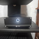
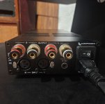
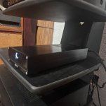
Thomann T. Racks DSP 408 Fan Noise

IMG_8734.jpeg


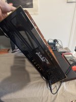
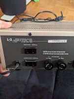
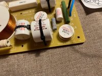
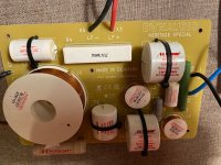
I recently picked up a Thomann FIR DSP408 speaker management system as an upgrade from my Dayton Audio DSP408. It’s an absolute beast of a unit: 96kz sampling, XLR ins and outs and no noise at all whatsoever in the signal. However, because it’s designed for PA reinforcement in questionable conditions, presumably loaded into racks with amps and little ventilation, it has a fan that runs all of the time. That’s a bonus for pro audio, but for home use, it’s a deal breaker that defeats the low noise floor of the signal.

So, for home use with constant 70° ambient temperatures and adequate ventilation, is there any reason to have the fan running at all? Are there aftermarket fan controls that I could use to slow the fan to a whisper? The T. Racks otherwise works very well and is about a third the price of comparable units, I just can’t tolerate the fan noise.

For Sale Lundahl LL1660S/18ma. Pair like new/never used

Here for sale a pair of new, never used interstage transformers from Lundahl, gapped for 18 mA.

This is the S version, with the extra Faraday shielding, optimized for phase splitting in pushpull circuits.

280€ Paypal friends and family

Attachments

  • image.jpg
    image.jpg
    1.1 MB · Views: 117
  • image.jpg
    image.jpg
    1.1 MB · Views: 100
  • image.jpg
    image.jpg
    1.2 MB · Views: 91
  • image.jpg
    image.jpg
    1,017.1 KB · Views: 98
  • image.jpg
    image.jpg
    962.1 KB · Views: 105
  • image.jpg
    image.jpg
    742.2 KB · Views: 120

For Sale Pair- Lundahl LL1663 - 50 mA.DC. Single-Ended Tube output transformers

Here we have a very nice like new pair of single ended output transformers from Lundahl.

These are gapped for 50 mAdc.

They’re basically in like new condition. I used them in a tubelab 300 B amp for a month or two. The rest of the time they’ve been sitting in my cupboard.

Brand new they cost €170 each.
How about €280 for the pair, PayPal friends and family, you pay shipping.
These are located near Vienna, Austria.

Thanks for looking, I have another pair of Lundahl LL1660 interstage Transformers also for sale, if you’re interested.

Thanks, Mac

Attachments

  • image.jpg
    image.jpg
    1.1 MB · Views: 134
  • image.jpg
    image.jpg
    1.1 MB · Views: 130
  • image.jpg
    image.jpg
    1 MB · Views: 132

Let's pool our resources to find some used SITs, power JFETs etc

I took a 2 year break from audio to get a brain break and enjoy a few other hobbies. I have spent the last few weeks looking around the Pass forum and see not much has changed, except the semi's have tripled in price since 2020. I am not in a position to fork out $400 for a pair of Tokin SITs or Sony VFETs so I'm going to throw out an idea for those of us in the same boat.

These devices first made mainstream in the 70's, and were used in a lot of industrial applications, inductive heating, inverters, motor controls etc, anything high powered and high voltage were the targets for the mfrs at the time. The scrap yards must be full of these things, and like the two main offshore guys who seem to control the market, you know who they are, can't be the only resourceful people out there.

I'm suggesting that there are plenty of guys here retired, or otherwise who have the time to research this, find some known manufactures who used these, put together a list of applications or devices that would be loaded with SITs and let's get out there and find some cheap devices. I live in a small town but am only 4 hours away from major cities with many salvage yards.

Anybody interested or am I off my rocker? Well, I know I'm nuts but I thought I would at least throw this out there for the masses to consider.

One other thought....there must also be some modern devices suitable, maybe even readily available. I know United semi and Infineon names have been bantered about here.

My silly season is slowing down and I soon plan on spending a lot of time researching these devices. I hope to build a few amps this winter that use these devices....just ordered a quad of the Edcor xfrmrs....

So what do you think?
Cheers for now! :cheers:

For Sale Regulators shunt and linear

For sale some regulators all of them have been tested tested and in full working condition. Postage at cost. Paypal for FF

1) Salas UltraBIB 1.3 shunt regulator
SOLD
UBIB.JPG

2) Salas BIB 1.1 shunt regulator
35 euros

BIB.JPG

3) LT1084 linear regulator 5A bought from Audiophonics
15 euros

LT1084.JPG

4) Flea super regulator (AD797) special for clocks (3.3VDC and 5VDC)
SOLD

flea.JPG

5) Twisted Pear shunt regulators for Buffalo 9018 DAC
7 euro each 25 for the lot

tridents.JPG

6) Opa based regulator with Xpresso clocks (12.288 / 11.28)
7 euros

clock_reg.JPG

500w IRS2092s based amp board

I have one of those china IRS2092s based amp boards that uses a xl7005a regulator fed from the Gnd to negitive rail through 3 parallel 20v 1w Zener diodes to drop the negitive rail of about 60 volts to 40 volts. I removed the zeners and replaced them with 1 120 volt 5 watt zener to the positive rail to run at 80 volt rails (160-120=40 volts). Powered it up and it worked for a second then blew the regulator.... Can't figure what went wrong, did this twice so far..... I want to equalize the current draw on the rails at idle and run at higher voltage...the rest of the amp survives 80 volt rails just fine. Checked the voltage after and it was 40 volts, what gives?

4-Band Parametric EQ

Freezing cold here in the Northeast USA has got me holed up in the apartment, so this seems a good time to apprehend the unique circuit found here.

Want more control over the mid-range for guitar. Found a different 4-Band ParaEQ PCB out in Europe but no answer to email, so no money will be sent.

Having trouble apprehending the action around what I have named, "Range Node", specifically, the phasing of the dual pot connections, i.e., the direction of the wipers and their effect. I assume it moves the range around somewhat.

4-band-qualizer-circuit-CROPPED2_edited-1 copy.jpg


Here is what I have figured out so far: when the wiper of VR2a moves downward, adding series resistance to C1, there will be less low end boost due to the higher XC, thus effectively moving the band higher. In the case of VR2b, it seems to me a conundrum whichever way that wiper goes in relation to the other. I have spent hours trying to understand what would be going on either way, with the exception that C1 and C2 will be in series, regardless of wiper direction.

Another question is there are no input caps on each opamp. A main incoming cap is elementary, but what about the rest of them? Adding them will produce a phase shift at each band stage around 90 deg. from the preceding. I wonder what that will do the to tonal qualities. Might try that after the ranges are adjusted to suit guitar, clean channel and heavily distorted channel. At that point, the dual pots will be replaced with fixed resistors.

Well, I could build it, and if it doesn't work, the pot leads could be reversed until it does (if it does), but that is really "bush league". This is akin to the difference between an automotive technician and a "parts changer".

Any comment appreciated.

Heathkit W5M power trans plus chokes

For sale is original Heathkit W5M power transformer made for Heath by Stancor
model 54-32 (Stancor part 138652)
117V , 910V CT 140mA , 6.3V 4A , 5V 3A -$99

Stancor Heathkit choke 46-12 , 138639 -nominally 7H , 140 mA , 160 Ohm . Measured 9.8H ,160 Ohm (inductance will go down with current) -$35
Chicago Heathkit choke RC-12205 -7H, 140mA , 160 Ohm. Measured 11H , 160 Ohm . $35

Attachments

  • IMG_5233.jpg
    IMG_5233.jpg
    678.7 KB · Views: 148
  • IMG_5235.jpg
    IMG_5235.jpg
    685.2 KB · Views: 139
  • IMG_5238.jpg
    IMG_5238.jpg
    515.4 KB · Views: 138

Acoustic G60-212

I was asked by a friend if I could look at an Acoustic G60-212 solid state guitar amplifier, to see if I could get going.

Found the drivers/finals to be blown, and now it works but isn't very loud.

Replaced the finals Q5/Q8 with 2N3055G and drivers Q4 with 2N5415 and Q7 with 2N3440

The measurements essentially show R6 in its centered position 4.7K ohms
If I turn R6 clockwise down to around 1.3K ohms, the amp really wakes up and sounds much better... But... the drivers get very Hot! 250F for Q7 and 200F for Q5

Another thing is the finals stay cool no matter the position of R6.

I am a definite Newb for amps, but have worked on other electronics for most of my adult life.
(I know which end of the soldering iron to grab..🙂

Any insights are definitely appreciated!

1742690096625.jpeg

Attachments

For Sale 4 Brand New 0.1UF 630V Audio Note copper Caps

(4) Audio Note Copper Caps .

Musics finest conductor. Copper foil Mylar in oil caps with 99% pure silver lead outs. (Qty-4), brand new,Never used Audio Note copper caps. 0.1 UF 630V. Bought these new in December 2024 from victor with intentions to use on a Elekit amp but the unit I bought already had some installed. These were received with superficial marks from storage/shipping as seen in the pics.

These retail new @ $58 each,
Asking: $49 each
Item will be well packaged.
All Sales Final
PayPal Only
USA Shipping/Buyers Only
No returns or refunds

Attachments

  • IMG_2211.jpeg
    IMG_2211.jpeg
    534.2 KB · Views: 86
  • IMG_2212.jpeg
    IMG_2212.jpeg
    594.1 KB · Views: 73
  • IMG_2214.jpeg
    IMG_2214.jpeg
    501.4 KB · Views: 60
  • IMG_2216.jpeg
    IMG_2216.jpeg
    584.9 KB · Views: 59
  • IMG_2218.jpeg
    IMG_2218.jpeg
    487.1 KB · Views: 74

My Thanks To The Moderators

I greatly appreciate the Moderators allowing me to join this forum site. I have much to share and am eager to learn. Read about me as follows.

I have a blog and a site where I provide free guitar lessons (without video), have published a free technical manual on guitar electronics,
upload my original music to SoundCloud and AudioMack, and have a site with all the chords to my songs.
Look for my posts under selected topics soon.

Here are my most important websites.
https://www.kurtusrichtersblog.com
https://hkurtrichter5.wixsite.com/guitar-lessons
https://hkurtrichter5.wixsite.com/electric-guitar-data
Login to view embedded media https://audiomack.com/hkurtrichter/album
https://hkurtrichter5.wixsite.com/chords-for-kurtus-ri


By the way, I have nothing to sell, not even my music or music lessons. It's all free.
There will be no posts from me trying to sell something.
Everything I give online is free to anyone with an internet connection.
And thanks again.

EOF

GB for Salas Folded Simplistic Phono PCB

UNDER REVISION FOR UFSP BOARD UPDATES

FSP ULTRA SCH.png


UFSPeverythingreverb.jpeg


2SK369BL matched pair - $12.50usd
2SK369BL matched quads - 26.00usd (LOMC Only)

2SK170BL's - 36 usd
Q4-Q5 and Q6 are now going to be custom selected with different R11 (for Q5) and R8 (for Q4). These will help adjust the currents to any matched pair of 2SK170BL.
This is to make better use of existing stock of 2SK170BL without any performance hit. R11 and R8 resistors are now included with the 2SK170BL sets.


Here is the new RAW PSU that people have requested. Use this before the Folded Boards Shunt Supply as described in Folded Guide.
These are 15.00 each.

IMG_1621.jpg

UFSP BOM

VISUAL BUILD GUIDE UFSP
IMG_1625.jpg

Attachments

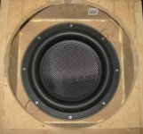
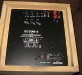
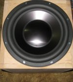
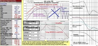
Is a BIC America F12 really that bad?

Is a BIC America F12 really that bad? I picked up one of these with a faulty amp for around the same price as Starbucks coffee.
I've temporarily converted is to passive and connected it to my LG home theatre system where it is probably crossed to high. It sounds okay, plenty of sub-bass but not too good with actual musical (air) bass.
I suspect the plate amp's problem is with the power MOSFETS and I've ordered some replacements.
I'm coming to the conclusion I'm only fixing this because I can. I don't really want it.
Should I trash the box and sell the driver?

Attachments

  • f12c.jpg
    f12c.jpg
    409.3 KB · Views: 33
  • f12d.jpg
    f12d.jpg
    315.6 KB · Views: 30
  • F12e.jpg
    F12e.jpg
    417.9 KB · Views: 34
  • f12f.jpg
    f12f.jpg
    174.7 KB · Views: 31

Hybrid ZEN Amplifier + LM317 = Efficient and simple

I have been working to convert the mythical Nelson Pass amplifier into a simpler one, with the addition of the well-known LM317 voltage regulator, in a curious way of operation. The result is surprisingly good.

Only 9 components, not counting those of the power supply.

Circuito.jpg


Bode:

Bode.jpg


Distortion profile envelope at 1W @ 8 ohms and 1 KHz:

Fourier a 1W sobre 8 ohmios y 1 KHz.jpg


Distortion profile envelope at 8,48W @ 8 ohms and 1 KHz:

Fourier a 8,48W sobre 8 ohmios y 1 KHz.jpg


PSSR:

PSRR.jpg


DC parameters:

Parámetros DC.jpg


Login to view embedded media
Best regards

Help with crossoverdesign

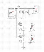
Trying my luck, and learning, to design a crossover for some drivers that I ordered and going to install in my car. I have chosen the Dayton Audio AN25F--4 and RS100-4.
I want to design a passiv crossover to get the most out of the install and tried my luck in Xsim. Pretty steep learningcurve and a lot of fun trying to adjust, to a point 😉
Maid a screenshot of what I have done so far. But not sure why the overall-line is lower than the original? Also tried to set a crossover between 3000-4000 Hz, but when I want to lower the dB on the tweeter with a resistor it goes to sh**, and it makes a massive spike below 2000 Hz which results in a massive peak og dip in the overall-curve.
Anyone go any tips for a good starting-point?

And, oh yes I am a total rookie!😀

Skjermbilde 2025-02-21 170926.png

Adding a resistor in series with relay coil?

IS there any logic to add a series resistor to a relay coil to lower coil current/watts/heat to enable a longer life span?

OR is that practice going to lower the pick-up tension of the contacts and lead them to overheat or not perform at their rated amperage?

Or does it just slow down contact response time?

I'm talking about 120 VAC 2500 ohm coils-ish and 15 amp loads on contacts.
120 volts drive and 120 volt slave relay controls in pinball machines and arcade console game machines.

Pure entertainment but in a retail/commercial establishment.

Cheers.

EDIT: I have always used octals in a socket but I have been asked to look at this type of relay for the purpose.

Attachments

  • PXL_20250311_230843814.jpg
    PXL_20250311_230843814.jpg
    167.2 KB · Views: 44
  • PXL_20250311_230750585.jpg
    PXL_20250311_230750585.jpg
    202.5 KB · Views: 38

CL08TL6 (2025 03) multi transmission line full-range

The CL08TL6 project is a multiple transmission line applied to a 3FE25 Full-range driver from Faital-Pro. Compared to my previous projects it is more compact, simpler, more rigid and with less spurious vibrations.

The dimensions are 260 x 260 x 1100 mm and can mount drivers up to 130 mm (5”). The footprint is similar to a floorstanding speaker.

The front emission is direct, therefore directional.

The rear emission is applied to a compression chamber on whose lower side are glued 6 rigid PVC waveguides folded on themselves.

The following is a list of the main differences compared to a standard transmission line with a single waveguide.

- The design is simple, it is not necessary to exactly match the resonances of the driver and the waveguide, the cabinet is neutral with respect to the driver used and the listening room. The length of the waveguides is calculated on the basis of the speed of sound in air, the electroacoustic parameters of the driver are not necessary.

- The 6 resonance frequencies (53.9 - 48.0 - 42.8 - 38.1 - 33.9 - 30.2 Hz) of the waveguides are evenly distributed over an octave with partially overlapping peaks, no sound-absorbing material is used.

- The 6 waveguides emit secondary wavefronts that are coherent and in antiphase with the frontal emission of the driver. The secondary fronts are delayed (4.6 - 5.2 - 5.8 - 6.6 - 7.4 - 8.3 msec) and emitted at different points in the space. Multiple emission increases the amplitude of the sound image, optimizes interaction with the listening environment and decreases listening fatigue.

- The support can oscillate at subsonic frequencies, isolating the compression chamber from the floor in the audible audio range.

- There is no simulation program capable of calculating the behavior of the CL08TL6 project, or rather, I do not have the time to study and test it.

On the same cabinet I also mounted 10 cm CL10TL6 (Ciare HX101) and 13 cm CL13TL6 (Ciare HX135) drivers that I had available. The Faital-Pro 3FE25 driver is fun to listen to and returns a wide and detailed sound image. With the Ciare HX101 the bass improves and the distortion decreases, finally with the HX135 you have a further reinforcement on the bass and the distortion decreases even more.

Thanks for your attention.

link:
https://www.claudiogandolfi.it
https://www.claudiogandolfi.it/cl08tl6.html
https://www.claudiogandolfi.it/cl08tl6.html#10
https://www.claudiogandolfi.it/cl08tl6.html#13

Attachments

  • tl8l03.jpg
    tl8l03.jpg
    59.2 KB · Views: 47
  • tl8d03.jpg
    tl8d03.jpg
    110.7 KB · Views: 46
  • tl8r03.jpg
    tl8r03.jpg
    49.1 KB · Views: 40
  • tl13d03.jpg
    tl13d03.jpg
    71 KB · Views: 46
  • Thank You
  • Like
Reactions: wchang and GM

Which switch is which?

Or, is it- which switch is which?

The switch shown below is for my AR XA reworked/rebuilt/super-duper turntable. The switch is used to turn the motor off and on.

Using the diagram shown just below the words, the switch (C-2), is wired as shown below. The light does not work on the switch and I also get a pop when turning off the switch.


IMG_2130.JPG


Anybody know how to wire the switch as shown on the switch?

Screen Shot 2025-03-19 at 9.33.52 AM.png


I'm thinking to myself that hot goes to the center prong, neutral wire with pigtail goes to the other two prongs?

Looks like a capacitor (what value?) and resistor in series??

Enquiring mind wants to know (me). I know I can just wire it all up thusly, but thought to myself that old turntable questions should have responses from some of the DIY gurus.

Thanks,

Dan

Add a subwoofer output to driver stage

Hi,

I'm about to add a subwoofer output to a 6SN7 driver stage (Williamson style). U1a is the amplifier; U2b is the phase inverter.
Too keep things simple I added a STP8NM60 MOSFET (or similar) as source follower. My idea is that the MOSFET will lot add a lot of load to the first triode (U1a),

According to LTSpice this seems to work OK. With only 1.1 mA and approx. 300 VDC across the MOSFET the dissipation is only 0.33 Watt.

kt150 versterker subwoofer aansluiting.png


Note: The original 100K plate resistor for U1a was split into 2 resistors of 85K and 15K. Adding C5 creates a short for AC. The reason for this change is to lower the gain without changing the DC settings.

Any additional suggestions will be welcome.

Regards, Gerrit

Qts on 30 year old Dynaudio 17W75 has shifted up to 1.25

I have a pair of old Dynaudio 17W75 woofers that had been in storage for many years. I just pulled them out of their enclosures and tested them. Qts has changed quite a bit and I assume that is due to hardening of the surround. Original Qts was 0.70. Do any of you know if replacing the surrounds is possible and economically viable?

Calling all EMS speaker owners

Hello DIYers,
I'm interested in EMS drivers but can't find many reviews from DIYers, hence, this thread. I'm particularly interested in a bookshelf speaker with the LB7 or LB6 driver. These are not cheap drivers and therefore would like to hear from those who have experienced them or any other EMS drivers. Best option would be an audition but unfortunately that wouldn't be possible.
If you have experience with these drivers, please post your comment. Tell us what box, bookshelf or floorstand, you've put them in and give us your pros and cons.
So let us know what you built and what you think.
  • Like
Reactions: androxylo

Anyone making Apogee bass panels?

Well, the subject pretty much says it all. Is there anyone here making, or capable of making, Apogee bass panels?

I have a pair of Caliper Signatures that will need replacement panels eventually and would prefer a more cost effective route than currently available. Please do not refer to the fellow in Australia, as that is not a cost effective route - he requires installation by his installers and does not supply only the panels.

Alternatively, would anyone know of a source for kapton/aluminum sheets? Time, and perhaps skills, would probably prohibit me from fabbing these from scratch but I may tackle the rest of the job (cutting and crimping) if compatible sheets can be had.

Any thoughts appreciated.


-Art

Jeff Rowland Coherence 1 - Schematic for the Modules wanted

This Thread exist already and is closed:
Jeff Rowland Coherence One Schematic - diyAudio

I want to have the schematics of this discrete jFET operational amplifiers:
1) Phono Amp Low Level
2) Phono Amp High Level
3) LINE AMP INVERTING
4) Line Amp NON inverting

Who can help?
The modules are similar to those from JC-2 (John Curl, Mark Levinson)
JC-2(220V仕様) Mark Levinson - HiFi-Do McIntosh/JBL/audio-technica/Jeff Rowland/Accuphase
Schematic of the main- and front board/power supply are in post #71 (page 8) under
Jeff Rowland Coherence 1 - Schematic for the Modules wanted

Attachments

  • Rowland Research Coherence 1 Phono low level module botton.JPG
    Rowland Research Coherence 1 Phono low level module botton.JPG
    22.4 KB · Views: 3,438
  • Rowland Research Coherence 1 Phono low level module.JPG
    Rowland Research Coherence 1 Phono low level module.JPG
    88.1 KB · Views: 3,372

What's the proper name for this "2 prong" power connector?

Google Image search tells me that the common reference is "Polarized" ... but is there a NEMA type for
this connector? I'm trying to adapt to my ancient roll of Monster brand flat 18 AWG to fit in the cast tray
of Beolab 6000 speaker. So a "right angle" solder-able edition would make it "perfect".

2 Prong Connector

54399142210_ff29646958_c.jpg

Attachments

  • power-cord-2-conductor.jpg
    power-cord-2-conductor.jpg
    148.9 KB · Views: 16

For Sale Free: 2x Broken Large Tru-Ohm Rheostats & 2x Octal Plugs

Before tossing these, I wanted to post here in case someone can use them for parts.

2x Tru-Ohm R-100 Rheostats (25Ω, 2.0A) – Damaged during shipping

2x Octal Plugs – Removed from a pair of Magnavox full-range speakers

Buyer pays shipping from Brooklyn, NY 11211 via PayPal / Zelle / Venmo.

Thank you!

Attachments

  • IMG_1989.jpeg
    IMG_1989.jpeg
    352.1 KB · Views: 26
  • IMG_1988.jpeg
    IMG_1988.jpeg
    391.2 KB · Views: 26
  • IMG_1985.jpeg
    IMG_1985.jpeg
    295.4 KB · Views: 25
  • IMG_1986.jpeg
    IMG_1986.jpeg
    350.6 KB · Views: 24
  • IMG_1987.jpeg
    IMG_1987.jpeg
    364.2 KB · Views: 28

NAD 3020e tone controls

Been playing around with a NAD 3020e today.

On my unit, I noticed that the tone controls are not neutral in the center position. There is too much high frequency peaking on the square wave. So if you own one of these, you might want to check yours.

The first image shows the default response with all tone controls in the middle. The second image shows the response after turning down the treble 2.5 dots. Bass seemed to be about right.

Cheers,

Attachments

  • 1.png
    1.png
    2.9 KB · Views: 89
  • 2.png
    2.png
    2.7 KB · Views: 75

4-way Altec PA Infos and Questions

Hello to all diy Soundexperts,
I want to build myself a PA (for 50-100 People, electronic dance music) who is Inspired by altec, JBL or Onken to name a few.
I going to build 2 good sounding 3 Way Tops which i also can use at home and 2 18" subs for Outdoor Purposes.
So for the 3 Way tops i tought about the following.
i got myself the CAD plans for the Onken SC-500 inspired Horn from Joseph Crowe which i want to cover the mids and highmids.
Í thought about building some low mid/mid bass cabinet like Altec 817 to match with my Horns.
then I only need some tweeters or something like that for the High end.
I wondered if i could use the 1000HZ version of the Yuichi Horn or do I need a real Tweeter?
I would start building the tops and begin with the Onken Horn.
then i am planing to build the altec Cabinets, so i can messure them before designing the tweeter with a 3 way Crossover.
after i build the tops i would build myself the 2x18 " subs which i want to add if i need some subbass outdoors.
I am wondering if i can do a 2 way crossover for the subs and the tops? So the Signal is running trough 2 Crossovers to the tops. Should be Possible or not?
and how do i split the signal out of my mixing desk (Symetric/3Phase Signal) to get a speaker signal (unsymetric/2Phase) to the tops and a normal audio Signal (symetric/3Phase) to the Subs? Or am i mistaken something here?
Any leads to good sounding drivers with a fair Price are appreciated, thanks in advance for your Answers and Ideas.
Freddy🙂

Unhumping a Magnavox

I just recapped a nice little Magnavox 164BA amp. I was surprised to see the frequency response is not flat! not flat at all! looks like a Camels hump! two big peaks top and bottom with a scooped out mid section. I have to imagine this was done on purpose??? I know Sam's schematics are often wrong, but the value of caps i used matched what was in there.

Looking at other Magnavox schematics, I see some differences. I am guessing i should remove C5 and maybe C7??

Attachments

  • 164BA.jpg
    164BA.jpg
    179.3 KB · Views: 159

Keeping it simple

Let’s say you’re building a passive preamp, whether it be a typical attenuator or maybe an autoformer, and you wanted two inputs, one for a cd player and a tuner - and one output for a power amp. Really basic, right?

Keeping it really basic, let’s say you don’t want to include a source selector switch. You could have one pair of input jacks on the preamp and plug in the CDP interconnects when listening to cd’s, and unplug those and plug in the tuner’s interconnects when listening to the tuner. Or just have one pair of interconnects and swap one end back and forth between sources, while keeping the other end permanently connected to the preamp. Kinda of a hassle, but I’m sure there are some that do this.

Are there other ways to handle the two sources without the use of a selector switch? What about having two pairs of input jacks (one for each source) and have them both wired to the volume pot? Since you would be listening to one source at a time, would the fact that the other input jack being wired to the volume pot (with no signal input of course) have any detrimental effects? Would there be any capacitance issues?

Infineon MA12070 Class D

Just saw this new amp IC being used in the SMSL SA300. The specs look impressive. 45uV noise with audio source off. 0.004% THD at higher power (not sure what power but not max). Max power in the usual 40w range for 24v supplies. Built in I2C serial data bus for DSP programming and basic controls.

MA12070_QFN-64_Combi.jpg_1634788313.jpg


Features from website:
Summary of Features

attachment.php


Multi-level switching technology with 3-level and 5-level modulation
2×80W peak output power (26V PVDD, RL = 4Ω, 10% THD+N level)
Supply voltages: +4V to +26V (PVDD) and +5V (A/DVDD)
Suitable for 2.0, 2.1, 4.0, 1.0 output stage configurations
4th order feedback error control
<160mW Idle power dissipation (26V PVDD, all channels switching)
>80% efficiency at 2W power (1kHz sine, 8Ω)
>91% efficiency at full Power (1kHz sine, 8Ω)
Audio performance (PMP2): >110dB SNR (A-w, rel. to 1% THD+N power level)
45µV output integrated noise (A-w)
0.004% THD+N at high output levels
I2C control (four selectable addresses)
Built-in protection: under-voltage-lockout, over-temperature warning/error, short-circuit/overload protection, power stage pin-to-pin short-circuit, error-reporting through serial interface (I2C), DC protection


MA12070 - Infineon Technologies

https://www.infineon.com/dgdl/Infin...N.pdf?fileId=5546d46264a8de7e0164b750002861a5

Uses the so-called Multilevel Class D topology for the highest power efficiency, greater than traditional Class D - whitepaper:
https://www.infineon.com/dgdl/Infin...N.pdf?fileId=5546d462696dbf120169b4f8f7524db9

Applications:
https://www.infineon.com/dgdl/Infin...N.pdf?fileId=5546d462677d0f460167bba4f4e81abd

The SMSL SA300 which has got to be the highest feature packed per dollar DAC/amp I have seen.

If anyone has experience with this new chip please share. Getting the SA300 is less expensive than getting the Eval board from Infineon.

Is this the new “TPA3116 Juggernaut” of the 2020 decade?

Attachments

  • FFB3B1C5-3A85-4010-8AD1-0A0822680EC2.jpeg
    FFB3B1C5-3A85-4010-8AD1-0A0822680EC2.jpeg
    144.1 KB · Views: 28,479

SB Acoustics Satori MR13TX-4 5" Textreme Midrange

SB Acoustics Satori MR13TX-4 5" Textreme Midrange​

MAY 12, 2024
Screenshot_2024-05-12_092828_480x480.png

I this post I test the SB Acoustics Satori MR13TX-4 5" Textreme Midrange. This is midrange only version (MR) of the Mid-woofer (MW). This is a new product for 2024 and Mark from SB was kind enough to send me a pre-production sample by request. I have been looking for a good all-around 5" midrange for a variety of projects which I will get into at later blog posts. But for this blog post I want to focus on the the raw test data.
IMG_9901_480x480.jpg

Features
  • Advanced TeXtreme® cone
  • Inverted soft low damping rubber surround
  • Extended copper sleeve on pole piece
Manufacturer's Published Specification Sheet click HERE.
The most interesting feature of this driver is the textreme diaphragm. I was curious to see just how high the breakup region is which should be well past the typical surround breakup.
Besides the diaphragm, how does the motor perform in terms of distortion? Let's find out!
Test Setup
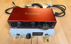
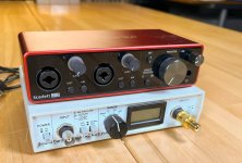
I decided to test the MR13TX-4 on my 90cm x 90cm IEC test baffle which in addition has a 8.6L sealed rear chamber measuring 13cm deep x 24cm wide x 24cm tall. I first measured the driver using a 30cm mic distance gated to 7cm where the first room reflection occurs. I then measured using a 5cm mic distance and spliced this ungated measurement in at 575Hz for the low frequency portion of the measurement. I applied 1/24dB octave smoothing for above 275Hz and 1/3 octave smoothing for below 275Hz. My measurement mic is an ACO Pacific 5012 running into a Scarlet Solo Mic Preamp.
Measurements
Let's start by looking at the manufacturer's published frequency response. High level we see an average sensitivity of 90dB through the midrange along with a breakup mode at 5.6kHz. The driver starts to become directional starting at 4kHz.
Screenshot_2024-05-12_080302_480x480.png

Showing the same zoomed in...
Screenshot_2024-05-12_080903_480x480.png

Below is the MR13TX-4 frequency response (red) with the impedance (green) overlay for reference. My measurements show a very linear response right up to breakup at 5.7kHz.
SB_Acoustics_Satori_MR13TX-4_20kHz_7.5L_Sealed_IEC_Baffle_480x480.png

I then extended the same measurement out to 50kHz. It's interesting to note that we see output all the way up to 22kHz. This means two things...that the diaphragm is likely not breaking up and what we are seeing is simply surround breakup effecting the response, and secondly, that the motor has very low inductance. We can see this in the impedance sweep where there is very little inductive rise into the upper treble. Very interesting!
SB_Acoustics_Satori_MR13TX-4_FR_480x480.png

Moving the mic back from 30cm to 100cm to conduct off-axis is shown below. I measured at 0,15, & 30 off-axis. (SB measured at 15, 45, and 60). Below 500Hz I spliced in the ungated response of the same measurement. At the 1m mic position there is a slight bump in the response centered around 250Hz which is likely the result of the 90cm x 90cm test baffle.
SB_Acoustics_Satori_MR13TX-4_0_15_30_Off-Axis_large_5f4651a8-682a-4cc2-901a-3d893610d724_480x480.png

With my results, directivity starts to narrow at 5kHz which is a little higher up than SB's off-axis results at 4kHz. So my results are actually a little better than published. This means that you can push your crossover point just a little higher if needed. Side note... This almost is a candidate for a wide band full range driver and appears to only need a super tweeter coming in at perhaps 8kHz?
Impedance
Looking at the impedance mounted in the 8.6L enclosure is shown below. This raises the FS from the factory 44Hz to 76Hz.
SB_Acoustics_Satori_MR13TX-4_Impedance_480x480.png

Time Domain

General comment on Time Domain
The time domain aspect shows the midrange driver's behavior after the signal has ended. The CSD plot looks at the behavoir in terms of time. We can see below that the 200Hz region takes around 3ms to fully die down below -25dB. The burst decay shows how many cycles are required for the signal to die down, which is a more relevant metric in terms of audibility. For example, the 200Hz region shows no issues in the Burst Decay, since 3ms is only a fraction of one cycle at the 200Hz frequency.
Another way of examining this result is to look at the 1kHz region on the CSD. We see that things die down quicker than 0.80ms for this frequency region. Since 1kHz takes 1ms to complete a full cycle, we can conclude that the woofer is able to die down within the time it takes for the woofer to complete one cycle.
Below is the CSD waterfall plot showing excellent behavior across it's usable bandwidth.
SB_Acoustics_Satori_MR13TX-4_CSD_480x480.png

The burst decay is shown below, again an excellent result.
SB_Acoustics_Satori_MR13TX-4_BD_480x480.png

Distortion
I started with harmonic distortion placing the mic at 5cm from the diaphragm. The driver required 1.5V to produce 85dB at 1m. Distortion is below 0.10% with the exception of the resonant peak at 4.7kHz. Distortion is still very low even above this region. If the peak was EQ'd out then the distortion would in this region would also disappear.
2584_SB_Acoustics_Satori_MR13TX-4_85dB_Harmonic_1.5V_480x480.png

Increasing the test SPL to 95dB requires 4.60V and we see a slight rise in H2 for the upper midrange. Otherwise H3 and H4 remain very low. (below 0.10%)
2584_SB_Acoustics_Satori_MR13TX-4_95dB_Harmonic_4.6V_480x480.png

Intermodulation Distortion
I then produced a 12 band per octave test signal ranging from 200Hz to 20kHz which required 0.80V to produce the 85dB at 1m test signal. Generally we see around 65dB of dynamic range with surprising clarity in the upper treble as well. Again, if the peak at 4.7kHz is notched out with an EQ, we would see a very good result indeed.
2584_SB_Acoustics_Satori_MR13TX-4_85dB_IMD_0.80V_480x480.png

Increasing the test SPL to 95dB required 2.73V and reduces dynamic range to a correlated amount of 55dB. Generally we don't see any stressing behavior at this elevated SPL.
2584_SB_Acoustics_Satori_MR13TX-4_95dB_IMD_2.73V_480x480.png

Gedlee Distortion (Gm)
The Gm distortion is shown below for the 85dB and 95dB sweep. Gm uses a dual tone test signal and weights the distortion product (Gm) towards types of distortion that we find more offensive than others. Generally we can conclude from this result that the driver is slightly stressed in the upper midrange at the higher SPL, but the overall result is quite low.
Gedlee_Metric_85dB_95dB_480x480.png

I tested the MFC 5" woofer from SB (shown below) and the result was slightly higher Gm for both test SPL's. So the MRX woofer excels in Gm compared to SB's more affordable woofer models. Please note the result below should only be looked at below 2kHz since my quick test was conducted with the woofer mounted in the the 1159 stand mount 2-way speaker.
Screenshot_2024-05-12_090034_240x240.png

Picture5_480x480.png

Conclusion​

The MR13TX-4 is an exciting new product from the SB Acoustic Satori line up. The driver exhibits a very flat frequency response which indicates excellent time domain performance. The distortion profile is consistent in terms the H2,H3, & H4 ladder effect where we see H2 dominant at elevated SPL with H3 and H4 lower down respectively. I personally find this this ladder attribute remains a consistent metric to correlated sound quality. And lastly the Gm metric is very low when directly comparing against the more affordably priced MFC woofer from SB Acoustics. SB Acoustics has done its homework on producing an excellent dedicated 5" midrange.

Midrange suggestions

Reading about @perrymarshall ’s Bitches Brew and other OB creations is an inspirational experience.
I already own some drivers etc that would could be used for a Bitches Brew inspired speaker. I have 4 x 18” woofers that have a sensitivity of 95db, so I’m thinking 2 per side. I also own a pair of ES 1200 biradial horns, so rather than use a coax for the mid + tweeter, I’m thinking this horn fitted with a 1” throat CD plus a suitable mid range driver. So I’m looking for suggestions for the mid range. It needs to be at least 98db sensitivity, be usable over say 150hz to 1500hz and to avoid beaming problems probably needs to be no bigger than 10”. All suggestions gratefully received.

Turntable Tachometer and motor speed controller

This is a group buy for the combined turntable tachometer with motor speed controller that uses the feedback from the optical sensor to keep the speed locked at 33.33 or 45 rpm. The control loop uses PID control. You can just use the board as a drop in-replacement for the Linn Valhalla board without the sensor and OLED display if you wish to solve the heat and unreliability problems of the Valhalla and just get electronic speed switching. Works fine with other turntables that use compatible synchronous motors.

The full thread discussing the development is here:
Digital Tachometer for record player (LCD display)
Features:

• Electronic switching between 33.33 rpm and 45 rpm (no more pulleys)
• Highly accurate sine wave frequency synthesis generated for 50Hz or 67.5Hz controlled to 0.001 Hz
• Class A motor drive circuitry.
• Optional optical platter feedback sensor to lock platter rotation at exactly the right speed. This runs a PID controller loop reach maximum speed quickly then keeps rotation speed locked rock solid.
• Control over motor parameters such as frequencies, phase angle, voltage amplitude via a USB serial interface. Adjusting these values enables smoothest motor operation with minimum motor noise and vibration. Values may be written to EEPROM once optimum setup achieved.
• OLED display to indicate exact platter rotation speed and WOW
• Fits on original Linn Valhalla mounting
• Can connect to original Linn power switches.
• Speed change controlled by holding power switch for three seconds
• Less heat generated than original Valhalla due to redesigned PSU section (no more burned out resistors).
• May be used for other turntables that use a two phase synchronous motor such as Airpax, Premotec, Philips e.g. Rega, Linn, Manticore, Pro-Ject etc.
• Can be housed in a separate box.
• Uses standard commonly available low cost parts such as Arduino, AD1933 DDS generators, common transistors.

There are three options:

1) Bare PCB and Pre Programmed Arduino Nano 18.00 GBP
2) Full kit of parts as per attached BOM in above thread 58.00 GBP
3) Fully assembled and tested board 98.00 GBP

a) If you want the optional FFC / FPC RA header so you can use a Linn flexible circuit switch (e.g. if fitting inside a Linn LP12 replacing a Valhalla) then that's 1.00 GBP extra.
b) Recommended round momentary push switch/LED to fit OLED enclosure (see below). £4.50

Options 2 & 3 are complete with all parts (I2C 128x32 OLED display, DDS generator PCB's, Arduino, IR detector, passives, semiconductors, heatsinks. terminal blocks etc.). All you need to add is a power switch (momentary action), indication LED and external enclosure for board (if not fitting inside TT). You will get a 3D printed box for OLED & Speed sensor. You can also use this box to mount a stop/start/speed change switch.

If you want shipping outside of UK please contact me with your address and I will work out how much extra it will be. Some examples of tracked pricing are Europe £9.35 USA £10.55 GBP

This kit contains a SMPS that is not isolated from the mains supply (similar to Linn Valhalla board). I recommend you build and test with an isolation transformer/step down transformer (100 - 240v @ 120mA) for safety of you and your test equipment. You must be confident and competent working with voltages 90V - 320V.

The above being said, the kit is straightforward to build and I will provide full comprehensive instructions on safety procedures, modular build and testing plus actual setup with your turntable. There are some SMD resistors to solder on the underside of the board. The most difficult part is tuning the PID parameters via serial interface/tuning application but some examples are supplied.

As a reminder these boards are designed to work with 2 phase synchronous motors 50Hz/60Hz that work off 6V - 110V RMS (160v p2p) that have a current consumption of approximately 10mA per phase. AKA Premotec, Airpax, Philips motors as used in Linn, Rega, Manticore, Pro-Ject and other compatible turntables Two boards can be stacked to drive 3 or 4 phase motors. You may be able to use them on shaded pole motors by using a single phase as long as the voltage and current requirements match the board specifications above. I have not tested on anything other than synchronous motors. If your motor draws more current/voltage then you will need to use an off board supplementary amplifier as per Pyramid's SG4. This motor controller can be used as a source for the sine waves and to handle the tacho & feedback/control functions.

To proceed with the group buy please add your name to each of the categories below. Please copy and paste the whole list each time you post so the list contains running additions and I don’t have to go hunting through each thread.

1) Bare PCB and Pre Programmed Arduino Nano 18.00 GBP
2) Full kit of parts 58.00 GBP
3) Fully assembled and tested board 98.00 GBP
a) Linn Valhalla switch connector option 1.00 GBP
b) Momentary action switch/LED to fit OLED enclosure 4.50GBP

Attachments

  • Controller-min.jpg
    Controller-min.jpg
    909.9 KB · Views: 4,465
  • SMD-min.jpg
    SMD-min.jpg
    832.9 KB · Views: 3,967
  • 20200216_165358-min.jpg
    20200216_165358-min.jpg
    469.9 KB · Views: 4,157
  • 20200104_151018-min.jpg
    20200104_151018-min.jpg
    546.7 KB · Views: 3,952
  • Like
Reactions: Paulo Batista Gomes

Bridge+Parallel amplifier

Hi all!

Hope I'm posting this in the right category.

I'm planning on adding a sub to my car's audio system, and would like to use the amp I currently have. There's 4 spare channels on it, that I would like to leverage instead of getting a new amp. Couple of snags with my plan so far:
  • I don't know exactly how much power it can handle per channel. It's an older car, and despite my best efforts to obtain somewhat of a manual or datasheet on the amp, I'm coming up empty. That being said: I'm using 80 Watt (RMS) speakers in the rear, which seems to work without problems, so it's safe to say it can at least handle that.
  • The sub I'm planning to use is rated at 250 Watt (RMS), and 4 Ohms nominal. The impedence is fine, as my current rear speakers are also 4 Ohm, but the 250W seems far off from the 80 I'm sure it can handle.

I've read into it a bit further, and ran into an article on Wikipedia about wiring amps in parallel & bridged mode. From what I understand, bridging an amp -theoretically- quadruples power handling, but also halves the impedence the amp 'sees'. Thus, briding two channels would give me the power I need to drive the sub, but would now make it impossible impedance-wise.

The wikipedia article then goes into the possibility of wiring 4 channels into a brdiged-parallel topology: "[...] when both configurations are combined on a set of four single-ended amplifiers, the power output is increased four-fold but the power dissipation of each constituent amplifier is not increased [...]"

Forgive my perhaps somewhat simplified imagery here, but what I understand from this, is that I can set the system up in the following manner to obtain ~320W @ 4Ohm, enough to drive the sub I have my eye on (see image). That being said, Wikipedia isn't all that great a source, and I can't seem to find anything/anyone else on the internet using this setup. This has me a bit worried, and I don't want to blow any equipment in attempting this.

So. Assuming the amp can actually be bridged, some questions pop to mind: Does this actually work? Would there be any drawbacks to wiring it this way?

Many thanks in advance!

Parallel - Bridged Amplifier.png

Vinyl vs CD

Hi all,

So i have a question, i never usually listen to vynle but been asked to repair an NSM jukebox for someone.

Anyway today i finished recapping the amp and replacing dead transistors on one channel, full carriage rebuild and new stylus's.

That was the tip of the iceburg but you get the point its a proper rebuild.

Listening to records on it while testing, connected to modern speakers which i have heard before.

I am pretty sure that both spotify streams and cd should be much better than vynle but this thing sounds amazing i can hear every little detail in songs i have listened to on spotify and cd for years and im hearing new things i never noticed.

But why? Its suppost to be lower quality but this sounds much better to me.
  • Like
Reactions: Drbulj

Some Interesting Drivers, a New 3-way Project

Terra Incognita - Passive 3-way with 8" woofer

With my latest project complete, I have been thinking about what to do next. I want to work with drivers I have not worked with before, in a speaker system that is different from my recent projects.

The new Dayton signature series is intriguing. They seem to offer a lot of performance at a bargain price.

The SB26STWGC is also an interesting driver. It incorporates a small waveguide into the excellent SB soft dome tweeter. I have been quite impressed with the SB26STAC soft dome (flat faced) used in another project. The small waveguide of this tweeter provides directivity control above 3k, so it would seem to be most useful when combined with a midrange driver in a 3-way system.

SB26STWGC-4 / Fabric - Sbacoustics

I am also interested in doing something I promised myself I would not do… a 3-way passive crossover. The fact it is challenging and possibly frustrating also makes it interesting.

Normally my projects use sealed box woofers with DSP to extend the bass response. A passive speaker, on the other hand, should stand on its own and have sufficient bass response without external EQ. I have never worked with a passive radiator before, and this kind of system is intriguing.

I also want to build something which is modest sized and relatively uncomplicated to build. At this point I was envisioning a gross cabinet volume of 35 to 40 liters. I considered several form factors, including a a large stand mount and a very wide thing cabinet, but in the end, a small tower shape is what I decided upon. This will be another open source fully-documented design (like the LCCAM-10.3), so I want it to be speaker which has a wide appeal to many people with a variety of needs and rooms.

So the initial concept is a 3-way speaker using the SB26STWGC tweeter, a Dayton signature woofer, a midrange to be determined later, a passive radiator, and a passive crossover, in a floor standing tower cabinet. It should be easy to build, and it should be easy to integrate into a room, both sonically and aesthetically.

j.
====== ======== ======== ======= ======
Update 11/07/2024

1731018001799.png
1731018056828.png


Now that the project is complete, here is an index to some of the significant milestones

Assessing the SB26STWGC tweeter
post-7692926 https://www.diyaudio.com/community/...ivers-a-new-3-way-project.413182/post-7692926
post-7696156 https://www.diyaudio.com/community/...ivers-a-new-3-way-project.413182/post-7696156

Midrange driver evaluations
post-7706642 https://www.diyaudio.com/community/...ivers-a-new-3-way-project.413182/post-7706642
post-7707383 https://www.diyaudio.com/community/...ivers-a-new-3-way-project.413182/post-7707383

Driver vertical spacing discussion
post-7701644 https://www.diyaudio.com/community/...ivers-a-new-3-way-project.413182/post-7701644
post-7709700 https://www.diyaudio.com/community/...ivers-a-new-3-way-project.413182/post-7709700

Selecting the Dayton RS225 woofer
post-7713405 https://www.diyaudio.com/community/...ivers-a-new-3-way-project.413182/post-7713405

Construction photos
post-7739426 https://www.diyaudio.com/community/...ivers-a-new-3-way-project.413182/post-7739426
post-7741685 https://www.diyaudio.com/community/...ivers-a-new-3-way-project.413182/post-7741685
post-7757392 https://www.diyaudio.com/community/...ivers-a-new-3-way-project.413182/post-7757392
post-7788145 https://www.diyaudio.com/community/...ivers-a-new-3-way-project.413182/post-7788145
post-7819159 https://www.diyaudio.com/community/...ivers-a-new-3-way-project.413182/post-7819159

Woofer and passive radiator tuning
post-7762790 https://www.diyaudio.com/community/...ivers-a-new-3-way-project.413182/post-7762790
post-7775930 https://www.diyaudio.com/community/...ivers-a-new-3-way-project.413182/post-7775930
post-7788318 https://www.diyaudio.com/community/...ivers-a-new-3-way-project.413182/post-7788318
post-7791525 https://www.diyaudio.com/community/...ivers-a-new-3-way-project.413182/post-7791525

Passive crossover network adds gain to woofer response
post-7763605 https://www.diyaudio.com/community/...ivers-a-new-3-way-project.413182/post-7763605

Midrange driver response different than prototype
post-7764410 https://www.diyaudio.com/community/...ivers-a-new-3-way-project.413182/post-7764410

Filter design and development
post-7765990 https://www.diyaudio.com/community/...ivers-a-new-3-way-project.413182/post-7765990
post-7773253 https://www.diyaudio.com/community/...ivers-a-new-3-way-project.413182/post-7773253
post-7793179 https://www.diyaudio.com/community/...ivers-a-new-3-way-project.413182/post-7793179

System level testing
post-7789237 https://www.diyaudio.com/community/...ivers-a-new-3-way-project.413182/post-7789237
post-7791924 https://www.diyaudio.com/community/...ivers-a-new-3-way-project.413182/post-7791924

Design Document
post-7835459 https://www.diyaudio.com/community/...ivers-a-new-3-way-project.413182/post-7835459

MCCCB12 Introduction

Hello, I live in Oklahoma - but I have traveled all over. My background has been Satellite Communications, Telecommunications, and I currently work for the FAA as electronic instructor. I have numerous interests, but one of them has been speaker building. I am currently rebuilding a new system using an active system - miniDSP Flex Eight with a multichannel amplifier. I am hoping to try and conjoin an open-baffle system with an infinite baffle subwoofer. I'm looking forward to future interactions with others.

Rockford Fosgate T10001BD 2004

Hello everyone.

I have a Rockford T10001bd PC-5445-B amplifier.

The amp has good gate drive on power supply.
The amp is making rail voltage.
The amp is making regulated voltage.
There are no shorted outputs.

The protect light is lit brightly, the output stage is not getting any rail voltage to the rail switchers or outputs.
There is 2,250vdc on the output terminals.
Q202 and Q201 are getting very hot, but nothing else is getting hot, neither test bad in circuit. They are PZTA56 and PZTA06.

So far I have not been able to locate a fault, any help would be appreciated.

Designing a speaker for narrow dispersion (& Atmos ceiling reflection)

I am wondering how best to design a speaker to have the tightest lobe, beam, or dispersion. Usually, we try to have dispersion be as wide as possible, so the speaker sweet spot is wide. Here let’s go in the opposite direction.

One application might be to make a speaker for Dolby Atmos in which you can bounce sound off a ceiling. I know that such reflections are not a good way to go for Atmos. But I can’t reach my ceiling easily and don’t want speakers up there. (15 feet high, vaulted). Mostly, though, this could be a fun design exercise and I’m looking for a next speaker project. As simple as it may seem, I have not been able to find enough information on this topic. So let’s see what would make for the best design.

What is out there already:
I’m probably missing a lot. But here is what I have found so far. Most Atmos speakers look like the following. Basically, an MT speaker angled up. Probably spraying sound all over the place. Not good. Let’s not do that.
Klipsch.jpeg


There is an interesting thread here where horns and parabolic reflectors are used. But the conversation moves toward needing stadium level projection distances and the designs don’t seem suitable for, say, a house that you actually live in. 😀
https://www.diyaudio.com/community/threads/extremely-narrow-directivity-speaker-design.358588/
Hyperboline.jpeg


There are ultrasonic arrays, which give very narrow dispersion. My limited understanding is that they are not really good for music or movies.

ultrasonic.jpg


Then there are speakers with 4 drivers arranged in a square. Here is where things start to get really interesting. At least to me. There is a commercial option from Triad. And one DIY option:
https://www.avsforum.com/threads/javs-diy-dolby-atmos-mkii-modules.2378314/

inroom-silver-height-module8.webp


Four drivers in a square:
Let’s explore this idea some more. Will it work well? I don’t know. Any thoughts out there?

Look at the classic MTM speaker design. Note how the middle, dashed plot (2nd order Linkwitz-Riley, LR2) shows a nice, single lobe. Looks great so far. This image is for vertical directivity. If we also want narrow horizontal directivity, we would have a horizontal MTM. (Like some center channels.) Basically, we end up with the four drivers in a square plus a tweeter in the middle.
MTM.jpg


Crossover or no?
In the image above, notice how widely different the dispersion is depending on the crossover choice. An LR2 appears to be best for this current purpose. I do not know if that LR2 is electric, acoustic, or both. At any rate, I know that hitting LR2 is very challenging when designing a speakers. I have a couple of designs under my belt and was able to hammer things into shape and hit LR4. But LR2 is tough. And if we stray away from LR2, according to the image above, we may quickly lose the whole point of the exercise here.

So maybe it’s best to have no crossover at all? A full range speaker. With 4 drivers in a square. Like the Triad and DIY designs mentioned above?

Which drivers:
I guess the first question here is whether or not there will be a tweeter used. If there will be no tweeter, I guess just find the overall best performing full range driver. If we have a tweeter and a crossover, maybe try to find ones that are as flat as possible in the crossover region to have some hope of hitting an LR2.

Another option might be to have both a tweeter and woofers, but try to, effectively, have no crossover. Find a tweeter with relatively flat frequency response. And a woofer that is also flat. And for each, they have a natural tendency to drop off output around the same frequencies. So that they, effectively, sum up to be about flat without any crossover. I tried a project like this for an MT design once and it came out OK, not super. Add a resistor to drop the tweeter output down to the level of the woofers. Add a low pass cap to the tweeter to prevent it from getting fried from pops when you turn on the amp. Otherwise no real crossover to alter the directivity.

As frequencies go low, directivity also decreases. So there is probably not much need for the drivers to play below, say, 100 Hz. But we can always cut that off with the processor, anyways.

Ideas?
I am curious to see what thoughts everyone might have on this topic. Thanks!
  • Like
Reactions: grec

Pb free solder as good as 60/40

Anyone out there know of a decent lead free solder which flows as good as the tried and true 60/40 or 63/37 Kester stuff?

Its mostly for reflow work repairing old stuff, so it needs to wet and flow just as good without 900 degrees of heat. Most of the older audio stuff uses wave soldered and hand retouched PCBs. You want to keep the heat down to a minimum with those more fragile, older though hole components.

Would like to do something different to before (speaker question)

Hello all,

I'm after some ideas please. Some time ago I sold my last speaker setup - 2 x xls10s in sealed boxes and a pair of sealed mtm speakers. The mtm speakers were made with 8 inch midbasses and 1.25 inch SB Acoustics tweeters crossed over at 1kHz.

I would like to do things differently this time. Just not sure how...

The original system was fully active (3way) with a low cost DSP. Still got the DACs and DSP and homemade / designed 4 channel amp. Would like to re-use these.

Have 2 x Dayton Audio RSS390he drivers and a QSC RMX4050 amplifier towards the new system already.

Not really limited when it comes to cabinet size. The room is 21ft long. Would like to be able to listen to organ music properly so need decent low end. No aversion to professional drivers. Need to keep cost reasonable.

One limitation of the original system was the listening sweet spot. It was about the width of my head.

The new setup needs to be an all rounder.

Any thoughts would be very much appreciated.

Thanks,

Paul

Anyone managed to program a JAB2+ with ICP5 and PC UI?

I've searched the forum and gone back and forth with Wondom, even sending them videos and having them respond with instructions to do exactly what I showed them I did in the video. Apparently I am not the only one. Even when I have managed to get the pcui to recognize the jab2+(by not following the instructions btw) it will not save anything...even when I close the software the save doesn't work, have to hit 'do not save' to get it to close.

I've tried two boards and multiple computers with the same result. At this point I've tried every order of connection. Any tips, tricks, different software, etc. greatly appreciated I really need to wrap this project up.

Jason

Mini-Line Array Box, But Used As A Center Channel?

I have had another terrible idea, and I'm looking for someone irresponsible enough to encourage me!

I want to build a center channel to go with my main speakers. My speaker design is a bit unconventional, so I'm looking for the same with the center channel: https://www.diyaudio.com/community/...on-of-integrating-multiple-subwoofers.401343/

My first idea was to use the same coaxial driver I have in my mains--12" B&C 12FHX76. But that would be a really tall center speaker! And I have found that while it plays down to 100hz reasonably well, the mids sound a lot better when I cross it higher.

So the next logical step is to do a MTM style center, but instead it is a WCW...woofer, coax, woofer. I'd use a 5" or 6" coaxial driver, probably B&C. And 2 woofers the same diameter as the coax.

Then I had the worst idea. Why not make a box like a line array boxes used in pro audio? It would be the MTM style, but the drivers are angled so they are closer together than a standard MTM design. I think this would help horizontal directivity? This one could be a 2 way or 3 way. The 3 way version would use a coaxial, and the 2 way would have a horn/ compression driver.

Right now I only need a center channel, but if it works out, I'd eventually build a few more for surrounds as well.

Requirements are frequency response from 100hz to 20k(-ish), 115dB (impulse, peak) across that range, and compact (i.e. thin) enough to work as a center channel. Drivers are 6" diameter or smaller, and use a compression driver/horn for high frequencies. I want the design to control horizontal directivity as much as possible.

This image is a good representation of the general concept. They are common in pro audio, but I've never seen a center channel made like this. It's probably a terrible idea?

Screenshot 2024-05-04 at 8.31.53 PM.jpg

For Sale Various PCB boards (USSA, Hifi Sonix, power supply, Hypex/Purifi input buffer (Koifarm))

I have for sale several empty PCB boards. Pictures are in attachment in the same order like below. Shipping worldwide.


1) USSA power amplifier boards (set of 2), price: SOLD

2) Hifi sonix Ripple eater power supply boards (set of 2), price: SOLD

3) Universal dual rectifier power supply boards (1 piece), price: 10 EUR (piece) + PP fee + shipping costs

4) Universal capacitor add on pcb board (1 piece), price: 5 EUR (piece) + PP fee + shipping costs

5) Koifarm (ex. diyaudio member) Purifi ET400/NCx500 passive input buffer (set of 2), price: 20 EUR (stereo set) + PP fee + shipping cost

6) Koifarm (ex. diyaudio member) Purifi ET400/NCx500 active input buffer (set of 2), price: 20 EUR (stereo set) + PP fee + shipping cost

7) FSSA power amplifier boards (set of 2), price: SOLD

Attachments

  • USSA pcb.jpg
    USSA pcb.jpg
    636.5 KB · Views: 216
  • Hifi sonix ripple eater.jpg
    Hifi sonix ripple eater.jpg
    530 KB · Views: 192
  • universal PSU.jpg
    universal PSU.jpg
    502.8 KB · Views: 176
  • cap board.jpg
    cap board.jpg
    421.9 KB · Views: 177
  • Purifi Hypex passive input buffer.jpg
    Purifi Hypex passive input buffer.jpg
    513.3 KB · Views: 186
  • Purifi Hypex active input buffer.jpg
    Purifi Hypex active input buffer.jpg
    475.5 KB · Views: 196
  • 20240531_185545.jpg
    20240531_185545.jpg
    546.5 KB · Views: 132

In search of guidance to resurrect Spearkerlab S7

I have a pair of Speakerlab S7 speakers that I bought as a kit in 1978, gave away in 2006, and have recently re-acquired. They have been abused (dropped) while not in my possession. When they were recently given back to me, one speaker was dropped hard enough to have the 12" woofer popped out of its RTV nest, and it appears the big mid-range resistor tore out the connection to the capacitor in that circuit during that event. I hooked up the one complete speaker that still seems intact and heard that wonderful sound that I loved so much years ago. I have decided to attempt repairs, as I would like to enjoy their sound for the time I have left, so am asking for any hints, tips, guidance in getting the heavily damaged speaker talking again.

It appears that one of the crossovers was damaged in that the lead from the 12uF 100V non-polar capacitor [Rubycon] (picture below) was torn out of the capacitor body. Paul Johnston from The Loudspeaker Store was kind enough to respond to my e-mail and get me started on the parts quest and not make the process complicated. My need is simple: I just want to get this damaged speaker working enough so it can work together with its aged (but apparently intact) partner for a little while. I would like to get close to the original specs in replacement before I seal up the cabinet with RTV. I don't have a "listening room" any more, but will simply stack the two and leave them wherever I can find room in my tiny office where I hide out. Won't be able to muscle these 95 pound beasts around much longer without help.

Getting the old RTV off of the woofer cabinet face is a challenge without tearing up the MDF mounting board - any hints other than being extra careful in peeling this nearly 50-year old stuff off without destroying the MDF?

I was planning on using RTV silicone to button things back up once it produced sound again - all the individual horns and woofers seem intact, and produce sound when tested. Hoping there is enough lip left on the MDF board for that woofer to hang on to. I will be heeding the advice of others here and refrain from hot melt glue. I am not in a good enough shape to install hardwood backer for T-screws. I suppose it's RTV and pray... any other thoughts appreciated.


RB in flyover country USA - Mountain time

Attachments

  • Clipboard_02-23-2025_01.jpg
    Clipboard_02-23-2025_01.jpg
    23.3 KB · Views: 76
  • Clipboard_02-23-2025_02.jpg
    Clipboard_02-23-2025_02.jpg
    56.6 KB · Views: 79

Intro

Howdy all,
I joined because I am a dabbler (at best) and appreciate the circuit designs and PC boards offered by the more expert members here. After focusing more on family and children, I am approaching empty nest and restarting hobbies from my younger days.
I come this way because of my interest in synthesizers (and generally electronic music) as opposed to home audio. My last project before my break was a Paia Theremin. I am currently interested in working on an active LP filter with tube amp as an experiment in de-digitalizing my analog-modeling synthesizer.

G
  • Like
Reactions: birdbox

Screws/bolts in wood - alternatives to threaded inserts?

I am modifying a speaker cabinet and need to have removable panels. The panels are Valchromat (a bit denser/stronger than MDF) and are 19mm or 12mm and some need to be screwed/bolted into from the side, therefore risking splitting.

For this reason I have planned to use threaded insert, e.g. m4 bolt into an 8mm (OD) threaded insert, 8mm insert goes into 12mm panel. Very tight if used on the side. And also may be a pain to align.

Is there any other way to do 'bolt-able' threads on MDF? Maybe some specific product that I can put inside a hole, then put a screw or a bolt in, let it dry and then screw out (i.e. it would not stick to steel), while still maintaining the reasonable integrity of the thread for infrequent re-use?

Invertors, solar power and renewables.

After the power outage in North America a few years ago most utilities no longer run their generators on voltage control, they run on power factor control and one power plant controls the voltage. Why? If all the generators are set to voltage control and a plant goes down, the smaller plants try to maintain the line voltage which makes them over load and trip out. This is what caused the big outage here.

Now the line voltages vary a lot more than they used to. Add in solar and wind from the individual consumer putting power back on the grid and not all the these systems regulating well (think cheap gear) and the issue is compounded.

I like the resistor. Simple solution for a simple problem.
Mike

Unexpected oscillation when signal goes positive.

So I was doing some stability testing and found that even without pure capacitance on the output the positive side of the amp breaks out into oscillation. What was interesting was when I tacked on a 1uF cap on the output it appeared to start off as a ring then break out into oscillation (video attached). Meanwhile the negative side was perfect. The oscillation is not there when the fault relay is open. I can attach a schematic if needed.

Attachments

  • 20250316_131824.mp4
    14.4 MB

Summing Schematics for Sound Consoles

Hey guys. Finally, I got around to assembling my own console. I already have ideas for channels and circuits for them, but the most important element is missing - the summing circuit. A mixer without a summing circuit cannot be a mixer. Yes, I certainly know many passive circuits of the simplest summing circuits based on potentiometers and 5 resistors. But this is not what I need. I wanna get vintage warm and flash sound and I am looking for active or passive summing circuits from SSL, API, Neve, Neumann, Studer. If you have such circuits or know where to find them - please tell me. Or can you tell me how the adder works, not necessarily the actual diagram, the main thing is to understand the essence and create something of your own based on it.
I've also heard about such a scheme:
Each channel has a neve 1272 or Neumann preamp at the input of the combiner, and then a fader and resistor based circuit that combines all channels into one signal. The idea as to me is not bad, but only for the section of groups, that is the sum of 4 groups in one channel or master channel, and then stereo isolation and output amplifier. But I need a summarizer for the channels as well. To be able to select the group to which the summarized signal will be sent. What can you say about it?

Martin Logan SL3 crossover issue

Hi

I posted below on the Martin Logan forum and was advised to try here. Essentially I have one panel not delivering high frequencies; it isn't the panel (they're quite new) and has been identified as the crossover/power supply. I have a techie who has done some diagnostic work and has asked some questions, below.

If you have any thoughts please chip in.

Techie questions:

  1. The EHT seems to be working and measures 2200 volts which is the same as the working board
  2. I have swapped over the 4 channel Op amp and that is working
  3. I have tested the high value electrolytics C3, C8, C5, C6 they are all OK
  4. I have replaced the triac - that is OK
  5. I have tested the transistors Q2 and Q3 – they are OK
  6. When powering up the LED lights OK but goes out after about 2 minutes

I would welcome some useful information such as:-


  1. A detailed description of the operation of the circuitry
  2. A test-point map with expected voltage readings
  3. Suggested probable fault given the info 1 to 6 above

ML want £309 for a board which 'usually solves the problem'. Am I right in thinking as it's the power supply board only, I don't need two boards to match speaker outputs?

Thanks in advance for anything you can offer!

Mike

Inverted electrostat inferior in distortion?

Some interesting comments by bolserst about inverted electrostats (Final, Loewe) hidden in a now closed thread about BG Neo10 magnetostatics:

https://www.diyaudio.com/community/threads/bg-neo-10-and-neo-8.204465/page-10#post-3016843

https://www.diyaudio.com/community/threads/bg-neo-10-and-neo-8.204465/post-3017520

Quote:
Most ESLs charge the diaphragm with a high resistance coating and drive the stators with audio signal from a step-up transformer.
- Advantage is vanishingly low distortion if coating resistance is high enough to achieve constant charge operation

Inverting ESLs using a highly conductive diaphragm and drive it with audio signal from the step-up transformer.
The two stators are connected to equal but opposite polarity HV supplies.
-Claimed advantage is 6dB greater sensitivity which is possible, but seldom seen in practice due to other design practicalities.
Results of comparison test between the two drive methods posted here:
http://www.diyaudio.com/forums/planars-exotics/199943-measuring-sensitivity-esls.html#post2779302

-Obvious disadvantage is the inherent non-linear driving force with conductive diaphragm,
not to mention the reliability issues with the conductive coating.


and on the question of whether inverted had inherently higher harmonic distortion

Correct.
For conventional constant charge method, force on diaphragm is proportional to signal voltage and independent of position of diaphragm in the gap.

For inverting method, force on diaphragm is proportional to the square of the signal voltage and is also a function of the diaphragm's position in the gap.
Projects by fanatics, for fanatics
Get answers and advice for everyone wanting to learn the art of audio.
Join the Community
507,724
Members
7,885,852
Messages

Filter

Forum Statistics

Threads
406,121
Messages
7,885,852
Members
507,724
Latest member
Samsquatch01