WHAMMY Build Questions

Hi,

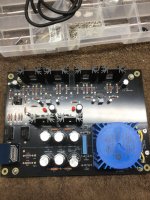
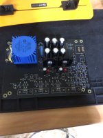
I am brand new to this forum. Please let me know if I'm violating any rules. I'm in the middle of my WHAMMY build and I am stalled due to missing/incorrect parts. I sent an email of to the diyaudiostore customer support.

In the meantime it seemed like the opportune time to ask a few questions about the build. I am building the stock version of the kit. Mine came with the AMVECO 12.5 VA + 12.5 VA/18 V + 18V transformer. I am using the red LEDs in the power supply section for reference voltage.

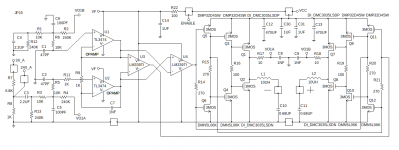
1) My op amp is labeled 458,000 JRC A133 A. I can't find the data sheet for it. Should I be using the optional 22uF/25V caps at C26 and C27 or should I jumper those pads? My understanding is that if this op amp is bipolar, I should use the caps.

2) In the build guide the shielded cable used for inputs/outputs has the shield connected at both ends....at the jacks and at the pcb. In all the preamps I have built I was advised to connect the shield at the jacks, but not at the pcb. Doing so, I was told, could induce ground loop hum. What should I be doing here?

3) I've read all the threads about wiring the panel mounted LED, but I'm still confused. A clear 5mm LED was supplied with my kit. Given the transformer I have at what specific pads on the pcb should the anode and cathode be attached? What value resistor should I attach in series with the anode? If after attaching the resistor I wish to lessen the brightness of the LED I could increase the size of the resistor, correct?

Thanks in advance,

John

Attachments

  • 09B5E976-2C21-4CAE-B211-B416C296FE75.jpeg
    09B5E976-2C21-4CAE-B211-B416C296FE75.jpeg
    510.5 KB · Views: 141
  • 5853BC73-DCD7-4F74-99DB-A4304B5F8385.jpeg
    5853BC73-DCD7-4F74-99DB-A4304B5F8385.jpeg
    425.4 KB · Views: 134

Adjusting capacitor values in this portion of the circuit, will it have a negative affect?

Hello all, I have a Mackie M1400i power amp that was having many issues that have mostly been resolved, but found some rail voltage where it shouldn’t have been and it was due to a faulty 270pF silver mica.

F7896B8A-322C-43D2-9E6E-FBB5F96241EA.png


So I plan to replace both C18 and C20 in both channels. What I have on hand are 330pF silver mica and 220pF and 330pF in both polypropylene and ceramic, not sure if dielectric matters here. Ultimately I’d like to swap in four 330pF silver micas, but want to make sure that increasing 60pF won’t cause an issue. I’m trying to save the $25-$30 I’d have to spend for four new silver mica and shipping costs.

Should I be okay with the 330pF mica or would be better to go down to a 220pF poly or ceramic?

Thank you,
Dan

Driver advice

I am looking for high quality replacement divers for 1980 ADS 1530’s
I need 4 high quality 10” woofers that can handle high and low volume power of about 200 watts from about 20hz to above 500hz
A midrange 4 “ from 500 to 2500hz and tweeters from about 2500 and up
I have been looking at scanspeak for the quality.
Any help would be great. My drivers got missed up by shippers.
Thanks

Karat mp-202c rusian cassette player-real shock for me

Yesterday i bought a karat MP-202 russian cassette deck at the flea market for like 2 dollars...it doesn't really work as some belts and idlers are worn , one resistor very hot...probably some regulator damage as well , but the overall design and transport left me breathless, especially one very ingenious feature around the capstan roller that can tilt , probably removing the posibility of chewing your tape even with a worn rubber roller, but i expect some feedback on that feature if it really works .I'll refrain myself telling more about the huge flywheel when i know russians also made some awesomely stuffed direct drive decks, but that looks impresive too and and the all metal-rubber belts and very simple yet efficient transport gave me a really solid feeling of something worth restoring and maybe looking for improving the electronics if needed as it only uses a DNL like type noise reducing system and just a universal tapehead, but maybe taking one of those transports and placing it into my favourite pioneer deck would be more interesting...Hopefully someone will help me with a schematic cause i can't find anything and i don't know how to look for rusian info.

Attachments

  • IMG_6175.jpg
    IMG_6175.jpg
    999.8 KB · Views: 264
  • IMG_6168.jpg
    IMG_6168.jpg
    1 MB · Views: 250
  • IMG_6171.jpg
    IMG_6171.jpg
    1 MB · Views: 271
  • IMG_6169.jpg
    IMG_6169.jpg
    948 KB · Views: 237
  • IMG_6165.jpg
    IMG_6165.jpg
    877 KB · Views: 244
  • IMG_6164.jpg
    IMG_6164.jpg
    1,004.5 KB · Views: 233
  • IMG_6163.jpg
    IMG_6163.jpg
    927.1 KB · Views: 221
  • IMG_6162.jpg
    IMG_6162.jpg
    795.9 KB · Views: 179
  • IMG_6161.jpg
    IMG_6161.jpg
    855.8 KB · Views: 183
  • IMG_6159.jpg
    IMG_6159.jpg
    957 KB · Views: 182

CS8416 in Software Mode

Is anyone here using the CS8416 in "Software Mode"?
If so, I have some questions.

I have built a DAC board with the CS8416 and the MAX9850. I have the I2C bus working nicely (connected to a PIC 18F2550) and I can read/write commands to either chip. But, so far - the only sound output is a few clicks.

Please share your init sequence. Here is mine (function I2C_W2 writes 2 bytes on the I2C bus):
Code:
r = I2C_W2(RXI2S_A, RXI2S_SADFMT, 0b10000000);	// set audio output port to Master mode
r = I2C_W2(RXI2S_A, I2SDAC_LRCLKH, 0b10001011);	// set Integer mode, DLY, 24 bit
r = I2C_W2(RXI2S_A, I2SDAC_DAUDIO, 0b00001000);	// set I2S data
r = I2C_W2(RXI2S_A, RXI2S_CNTRL2, 0b00000011);	// set GPO-0, red, to C bit
r = I2C_W2(RXI2S_A, RXI2S_CNTRL3, 0b01100000);	// set GPO-1, green, to NVERR

r = I2C_W2(RXI2S_A, RXI2S_CNTRL4, 0b10000000);	// set RUN

a) which of the 16 choices for GPOn best describes if the CS8416 is decoding a valid stream? I have tried the C (channel status) and NVERR, but they are always 0 (so far).

b) I have my CS8416 in Master Mode and the DAC in Slave Mode, does that make sense?

Thanks,
Jake

Burned out B&W 801F mid range driver

Somehow 😢 I've blown up a mid range driver on a 1984 B&W 801F speaker. I still don't know how I did it, but it has gone open circuit (well, about 1M) and has a very faint burning smell to it. The terminals are fine and I measured their resistance across the tinsell leads to make sure. This happened while the driver was tri-amped with a home constructed amplifier and I suspect that while I was testing different configurations of the amp earth wiring to minimise earth loop hum an output tranny has shorted and fried the speaker. The amp is fine. Base and tweeter are both fine, so it's a bit of a mystery and also a lesson to use a crappy old speaker when testing amplifiers.
What to do? Is such a fault repairable? Is there any other possible cause of these symptoms? Are there any drivers out there that would be a potential substitute for the original? I'm OK with soldering fiddly parts, but I doubt very much that my DIY skills would extend to voice coil winding.
I would dearly like to remedy this as the tri-amped 801s sounded absolutely heavenly.
Any advice very gratefully received.

CFA Amplifier for special application

Hello,

I have to make a class AB amplifier for high frequency applications (400 kHz - 700 kHz).
There is almost no literature in that frequency range so I started to learn about audio architectures to improve them.
I made a simple CFA schematic but I have not so much experience.
The amplifier has to deliver 15/20 W to a 20 ohm load (the load should be capacitive because is a piezotransducer).
Please give a look to my schematic to see if it shoud be ok or if there are little or big mistakes.
Any opinions to improve this design should be appreciate.

AMP.png

Kicker Amp

Not sure on the model number of this somce someone painted it at some point

Both channels have 4.50 volts measured directly across the speaker terminals .

I checked the outputs all test fine .

I’ve checked over a few other things diodes transistors resistors all test good .

Any ideas ?

Attachments

  • 1604550A-FC0D-4812-9858-455C964A7BC5.jpeg
    1604550A-FC0D-4812-9858-455C964A7BC5.jpeg
    662.7 KB · Views: 82
  • 3BE9730B-9FC3-4F7F-8767-0488C444AF11.jpeg
    3BE9730B-9FC3-4F7F-8767-0488C444AF11.jpeg
    638.8 KB · Views: 82

Convert DbA to Db

Does anyone know where I can find a table to convert DbA to Db?

You would think it is on the WEB but maybe I am just not very good at surfing. I am NOT looking for an online program--I need the power/freq conversion table or curve fit for this.
(I have a power meter that only reads DbA and I need a make a curve of relative power to frequency do I need to convert DbA to dB)

Thanks!
Fritz

To roll off full range mains with a subwoofer or not?

I am using stereo subwoofers with full range active 3-ways for the first time. The system is for music only, no movie effects. The subwoofer low pass is 70 Hz and is carefully phase aligned with the 3-ways woofer at this frequency. Should I install a woofer high pass at 70 Hz also? I realise this will save the woofer from exertion at low frequencies so it can possibly play cleaner in its pass band, but is there any downside? Is it preferable to avoid additional phase shifts caused by the extra crossover?

Crescendo 17k

I don’t wanna post both amps in the same thread to make things confusing.

Anyway I have another 17k amp here that was installed in the system when they used amp scope and blew 2 of the amps up the 3rd amp has issues also .

So the 2nd amp in the system which I have in front of me the owner states that it has Terrible feedback . He stated when powering the amp down it sounds like a vacuum cleaner turning off . Also when the amp is powered up there is a loud hum through the subs .

He checked the rca shield ground in the head unit which are fine also installed another amp in the vehicle and it has no issues so it narrows it down to this amp .

Any ideas on what to check or where to start since everything is testing fine so far

Wood working newbies: how to cut speakers' holes and curves

Hi,

together with my best friend I'm going to build a pair of Silbury speakers (but same applies to many other speakers) and I opened this thread to have confirmations that what I'm doing is correct, and information on how to properly do things. I'm reading this very interesting site: http://www.troelsgravesen.dk/ full of information, and indeed together with my friend we did a similar tool to drill holes.

By now we have tried to drill the holes in two steps on some samples of wood before drilling the wood dedicated for the speakers:
The rear chamfer has been done with this tool: https://m.media-amazon.com/images/I/51YyV9z+E4L._AC_SL1000_.jpg
The front hole has been done with this tool: https://m.media-amazon.com/images/I/61QI3Mab-iL._AC_SL1500_.jpg
The hole has been done by a tool similar to this one fixed to the milling machine: http://www.troelsgravesen.dk/tips/bb.jpg

I would like not to cut the big curve freehand, so I would like to ask if there's something I can build to properly cut the curve.

The third point is how to chamfer the sides of the speaker: is it needed to use again the milling machine with a tool like this one: https://m.media-amazon.com/images/I/41f3FpwBAML._AC_SL1000_.jpg or the saw incluned by 45°? How deep the chamfer must be on the side of the speaker?

Thank you in advance,

Roberto

SMD Class A Headphone Amp (THAT1646)

This project is inspired by the wonderful headphone amp by mediatechnology using a THAT1646 line driver in a novel way.
https://www.diyaudio.com/community/threads/simple-class-a-headphone-amp-using-that1646.163544/

You can buy the "Dual Class-A II Output" (DCAO2)" headphone amp here
https://ka-electronics.com/shop/index.php?route=product/product&product_id=67

This new project aims to design a small mono SMD version of the above amplifier in a balanced bridge configuration.

In addtion I will add a small signal peak detect to drive an external LED and maybe a delayed power-up to the opamp power rails to prevent power-on damage to the phones. First draft incoming.

Compactron Output Tubes

Hey guys,
Have any of you wandered across any compactrons suitable (or equivalent to another) for use as an output tube? I see a few here and there, but there aren't any curves for them. There are also some with fairly decent looking pentodes in them and an associated triode/diode. I wouldn't mind using the pentode only section I suppose.

I would like to stay with 12 or 6 volt heaters, and also the 6T9 is not beefy enough.

Rockford Fosgate 500X

Rockford Fosgate 500X, PC-3084B. Rebuilt channels 1, 2, & 3. Everything appears to be good, but with the input switch on 2 channel input, 3 & 4 emit white noise with either no input connected, or in addition to input. There's no noise from 3/4 with input switch on 4ch and 3/4 produce clean output. Channels 1/2 never have any noise regardless of switch position, and switch seems to be fine (cleaned with deoxit as well).

How is it picking up noise if it's getting signal from 1/2 which have no noise?

Hot Heatsinks In Vintage Amps ... Such As NAD C320

Vertical heatsinks on amplifier PCBs are a weakness since they dissipate heat poorly especially in a wide low chassis with insufficient ventilation. See in the attached photos where the NAD C320 is only partially vented on the top and even less on the bottom. The output stage has it's own shrouded heatsink which is slightly warm. The driver stage with the vertical sinks is somewhat hot. These two sections are under the vents. But the 18vdc discrete regulators are finger-burners. There are tiny holes in the PCB beside the regulator heatsinks which I suppose is intended to allow a wee bit of air to convection cool the heatsinks. Huh?

The C320 worked perfectly for thousands of hours until it began varying the audio volume intermittently. Such problems are difficult to troubleshoot. I need to fix it or visit the recycling depot. There are no obvious bad components but the internal heat dome is suspect.

In addition to poor ventilation, the input voltage to the regulators is excessive (38vdc for 18vdc out). This is probably a design choice to work with the toroid which has only two secondaries. One is tapped to produce 38v and 48v, the other is low-voltage for a 7805. So the 38vdc remains. I decided to install a custom pre-regulator for that. It reduces the regulator P=ExI value from 2.4 watts to 0.72 and relocates 1.68watts to the chassis metal on the mainboard perimeter. The amp works fine with 24vdc, not 38vdc, driving the regulator.

There is an option for additional cooling. Place a tiny 12vdc fan on the chassis cover such that it blows across the vented area. This is effective since it creates low pressure over the chassis and draws out some heat.

Attachments

  • NAD-case1.png
    NAD-case1.png
    604.4 KB · Views: 621
  • NAD-case3.png
    NAD-case3.png
    326.2 KB · Views: 400
  • NAD-cover.png
    NAD-cover.png
    592.3 KB · Views: 299
  • R45R46.png
    R45R46.png
    31 KB · Views: 296
  • NAD-317337a.png
    NAD-317337a.png
    287.9 KB · Views: 317
  • concept1.png
    concept1.png
    6.5 KB · Views: 318

Amp, PSU, CapMx pcb's for sale

If you are interested in below merchandise, PM me with your address, and I will reply with shipping quote. I ship small packet, insured, no tracking, unless stipulated. I have shipped all over the world with no problems.

1. Dx Super A amp & Dx PSU. PCB's from Juan Vargas and Carlos FM (Desroyer X). 2 sets available, each set has 2 amp boards and 1 psu board.
Photo is 1st one. Price is $30 USD per set.

2. DLH - Trilogy amp. PCB's from Horacio and Prasi. I have 9 boards.
Price is $3 USD per board. Photo is 2nd one.

3. LM4780 Classix Kit from Peter Daniels. Never opened.
Price is $50 USD. Photo 3rd one.

4. Partial built LM3875. Peter Daniels kit. Powered one channel before, but sold the transformers. Price is $25 as shown. Bypass caps on bottom of pcb. May have some caps laying around to include. Photo 4th one.

5. PSU for Chip amps from Mark Johnson. I have 3 board. Price is $2 USD per board. Photo is 5th one. Sold

6. Dual Rail SLB / Active Rect / CRC / CapMx / Class A PSU pcb from xrk971 / AKSA / JPS. I have 1 of these. Price is $15 USD. Photo is 6th one. Sold

7. Cap Mx from Analog Designs/Prasi. I have 10 boards. Price is $5 USD per board. Photo is 7th one. Sold 4 boards, 6 left for sale

8. CRCRC pcb from Analog design / Prasi. I have 2 boards. Price is $5 USD per board. Photo is 8th one. Sold

9. LT4320 active rectifier boards from Analog designs / Prasi. The boards are THT and I have 8 boards. There is 4 rectifiers per board. Price per board is $6USD. Photo is 9th one. Sold

10. LT4320 ideal rectifier boards from Analog designs / Prasi. The boards are SMD and I have 5 boards. There is 4 rectifiers per board. Price per board is $4 USD per board. Photo is the 10th one. Sold


Thanks for you interest,

Myles

IDx SA.JPG

DLH.jpg

LM4780.JPG

LM3875.jpg

MJohnson PS for chip amp.JPG

SLB Dual Rail.JPG

Analog design-Prasi CapMx.JPG

Analog design-Prasi CRCRC.JPG

THT active rectifier.JPG

LT4320 SMD ideal rectifier.JPG

DIY Build, What Provides Good Bass in the Circuit Topology of Power Amp Build?

Hi guys. I'm a beginner, I've built three amps and they all turned out great. Which was really encouraging with the hobby.

I'm planning two new builds. First is PTP wired gainclone monoblocks using LM3886. Second is an A/B mosfet 250w per channel power amp.

Basically I'm curious about bass. Within the design confines of minimal power amps such as these, what provides good bass? Someone told me that it's a combination of using an oversized transformer and quality power caps. But as I'm a beginner I'd like to ask you guys! Thanks!

Rubber vs. Foam Surrounds?

So.. I have this idea that keeps tickling the back of my mind about making a customised speaker driver and offering it for the DIY market. I think I can see a little niche, but do not want to blab about it yet when I have not even done a prototype. Please bare with me!

To do this I would need to create my own surround for the cone and I was wondering what the differences are between foam and rubber? Anyone got experience with driver design?

Perhaps does foam hit its excursion limits more gently than rubber, my assumption is that it can stretch a little more?

It might be my imagination but I feel I've seen more foam surrounds used in car audio and probably more in subs than midrange for example?

What do you know? 🙂

Microcontroler/and i2s commuting lines modification Denon DVD-A1

Hi, I have upgraded Denon DVD-A1 (8x pcm1704 , Alpha 24 procesosor, spdi freceiver input) a Mark levinson no360s analog IV stage is built in.
sound is much worse than Mark Levinon No360s DAC using same dac chips and same DAC IV I thought it was power suply (no360s uses discrete) so I put complete no360s DAC/IV boards to DVD-A1. to my surpise is still sounded much worse than No360s. now it was only the digital front end diferencies.

I looked deeper in the schematics of DVD-A1 and see that I2s doesn’t go from DIR to AL24 chip. instead of that it goes trought few DSP chips –DVD processor chip ES6038, and ADSPMEL322. so I connected i2s lines from DIR directly to AL24 chip and bingo- good sound at last.

I make micro small swithches near rj45 jack (denon link jack whch is perfectf or i2s input which I will add, remooved two chips to have this jack free from any conections)

now is problem with comutation. I do not want loose cd-dvd source. dvd-a1 have 3 source selector switch- DVD/Optical/Spdif I need this- WHEN DVD position is set relays are eneergized and i2s line ir connected ( or maybe is more elegant decisions) I am not familiar with micrcontrolers. How to get signal from it to relays to be energized when dvd rotaty position is set? thanks in advance.

Attachments

  • i2s .interface.png
    i2s .interface.png
    541.1 KB · Views: 196
  • i2s main.png
    i2s main.png
    842.9 KB · Views: 194
  • i2s rotaty.png
    i2s rotaty.png
    17.5 KB · Views: 189
  • i2s-dvd input.png
    i2s-dvd input.png
    10.6 KB · Views: 182

AudioSector LM4780 CZ Spec

Hello all,
I've been buying parts to complete my AudioSector LM4780 boards but the BOM info online is a little lacking. I have all the parts soldered up (including 0.5W resistors instead of the 0.25W resistors that would actually fit on the board) except for Cz. I see it's a 0.1uF capacitor, but what voltage rating is required for this? I can't find the info anywhere, it's not even listed as included in the kit from AudioSector

Thanks!

FREE: Vintage 1500uF, 450VDC Old Electrolytic Cans

Located in Carlsbad, CA 92010 for free pickup. I work down in San Diego and can meet there during my lunch break if needed.
There are eight Philips ones and five Mallory ones. They are 3" in diameter and maybe 5 or 6 inches tall.
I also have 8 of the 3" mounting clamps.
These haven't been re-formed in about 10 years.
1500uF-450VDC.jpg

DSC_0026c.jpg
  • Like
Reactions: adason and Grarea

Help calculating W-bin folded horn HIFI

I want to build horn bass speaker for my system. I have Dallas II with Fostex FE206EN and Monocor compresion super tweeters,playing trough KT88 SE amp.
Everything works nice,but im lacking deep and powerfull,clean bass. So i want to build bass horn.
I buy Eminence Kappa_Pro_18LF_8 and now i want to build a cabinet.
I have problem with space but i want to have nice horn bass sound,not vented box sound.
And i dont have much space. Worst thing is that i dont have enough deepnes for all design what i can find online.
So,i start to make design,change it 1000 times,and in the end,re-scale Klipschorn inside mesurments and put everything together and now i have some design which look ok.Looks,i dont know how this will sound and how low can i go whit this,is it ok for frequencis below 150 hz,etc.
I dont know how to calculate this design to see where is good and where is bad,do i need to change something...So here i humble asking for good souls who know how to put all parameters into calculator and calculate it for me so we can see where to go whit design.
I have to amps for this project,so i will see wich works better,one is digital 150W 8 Ohm,other is solid state 500W 8 Ohm,i take signal from speaker wire and cut it with active crossover at 150 Hz.
Here are pictures of design.

Attachments

Current Drive for Loudspeakers

There seems to be a dearth of information on practical ways of current driving loudspeakers, though I think I have looked at all that is available from Hawksford to "The natural way of driving loudspeakers". What is clear is that you get 20dB or more of reduction in distortion, quite apart from the distraction of thermal compression.

I have an idea of putting a capacitor in series with the "current sense" resistor, so as to roll off the current drive when it approaches the fundamental resonance of the system, and thus have the nice predicable voltage drive through that region and not, there, be affected by the change in impedance. But otherwise have current drive above there, even though that would mean a rising response with impedance.

It seems to me that the capacitor would only have to be a few hundred uF, so not fall into the trap of real power capacitors, but yet be quite good in that the ESR will have fallen to about as low as it gets for any electrolytic. Although this isn't the topology I think I would like to use in the end, though I'm not quite sure what that is right now, it nevertheless encapsulates the idea in a simple form.

I am well aware of the dependency on impedance that this whole thing implies, but was wondering if anyone thought this was a bad idea in principle. The idea is simply a transition from current drive to voltage drive when we get to the point that matters. (And incidentally I don't think I believe the very generously smooth curves that Nelson Pass published in his study of various Fostex and Lowther units with a high impedance drive. I think a very much more real peak should be apparent in measurements; and one that reflects the transition from a Q of 0.7 to a Q of perhaps 3 or 5, which is what it would be without electromagnetic damping.)

Incidentally, but quite pertinently, I don't like chucking away perfectly good signal in a power resistor, so bright ideas of how not to do that, but do the same thing more efficiently would be amazingly welcomed.

OME SIGMA-IV - last 4 PCB Boards For Sale

I I'm selling last 4pcb of excellent OME SIGMA-IV lateral mosfet audio reference power amplifier.

PCB Specifications:
  • 70um copper (2oz)
  • 1.6mm pcb thickness
  • red solder mask
  • white silkscreen
  • hasl pads
  • pcb drilled
For price and shipping cost please send PM and your country. Payment will be with paypal.
After payment PCB Boards will be send next day with tracking number.

Here is picture of boards and schematic:

OME SIGMA.jpg


1617347565031-min.jpg

Attachments

Help needed on 6th order Sallen-Key butterworth high-pass filter

Hi everyone, I've been looking for a reference or an article about formulas and calculations on the 6th order Sallen-Key Butterworth high-pass filter in "two stages" but I couldn't find anything. As you can see this is the Rod Elliott's 6th order Sallen-Key design but there is no explanation on how the calculations are. I've also checked out the Doug Self's book and found nothing. Any help will be appreciated.
IMG_20221101_181731.jpg

18W/Channel 3-15V Self-Oscillating Class D Amplifier JP15

I have been working on this project for years and I think that it is finished. Here is a Schematic of one Channel and a populated board showing the layout. It is typically designed for a 12V, 5A wall wart current limited power supply. It has low noise and low distortion but it has not been measured. It has 2 gain options of 3x and 24x through 2 RCA inputs. One channel oscillates near 300 Khz while the other channel oscillates near 250 Khz. The output stage features low crossover distortion because of its zero dead time design. It consumes about 2 Watts of standby power because of the bias in the output stage. The discrete nature of the design allows a hobbyist to use better op-amps and bigger output Mosfets and different dead times to change the noise level and the distortion level of the amplifier. The purpose of the design was to get low distortion power while using no heat sinks. Eighteen Watts of power per channel is relatively small in the class D world but that makes it affordable and 18W of power can be quite loud when applied to efficient speakers.

Attachments

  • JP15.png
    JP15.png
    27.1 KB · Views: 154
  • Like
Reactions: ASCTim

Goodmans HT-97 and other questions.

I'm still trying to create my ideal desktop system. I have an 8" sub at my feet - it's brilliant, no complaints. What I'm trying to achieve is a system that still sounds acceptable with the sub switched off (neighbours, party wall). I had a pair of Sony SS-CPX1 on my desk - it was all working. But then I bought a pair of Goodmans HT-97s for £2. Bigger driver, bigger cabinet . . . more bass, right?
No. The Sonys (top) produce more bass but the Goodmans tweeters are loud and harsh but sweet. I'll guess 5 or 6 dB above the Sonys - my ears are ringing. These are very old speakers. Could it be a cross-over issue?
I'm minded to put the Goodmans tweeters in the Sonys and ditch the rest. But I don't want to be told that HT-97s were really great speakers back in the day . . . and I just threw a pair in a skip.

Attachments

  • desktops.JPG
    desktops.JPG
    142.7 KB · Views: 144

2.5 way how to get a correct port measurement to be merged with nearfield

I am wondering how to proceed to get the correct port measurement in a 2.5 way. Both upper and lower drivers are needed to simultaneously produce the correct tuning frequency, but when one driver is disconnected and I take a measurement on one driver only , I get a queer port bump as can be seen in the 2nd pic.
1st pic is the normal measurement with both drivers connected.
My aim is to get the correct measurements procedure in view to merge port and nearfield for merging in the first instance and then get the farfield and finalising them all into a quasi-anechoic FRD for xover purposes. Can anyone help? I did not find the solution on the forum.

Attachments

  • Port with upper and lower bass tied.jpg
    Port with upper and lower bass tied.jpg
    103.3 KB · Views: 79
  • Port lower bass only.jpg
    Port lower bass only.jpg
    99.4 KB · Views: 75

MTM design questions

Im making a very basic MTM center speaker. Using Two 4ohm 6.5" midrange in series with an 8ohm tweeter. two questions


1) 1st order low pass I assume I treat the pair of 4ohm mids in series as a single 8ohm woofer?
ie: single 0.2mh inductor before the 2 mids in series. for ~6300hz cross (not a 0.1mh before each woofer)


2)For design Its being built into the tv stand.
I have upto 26" width, 13" height, 18" depth for the center. Should the tweeter go above the mids, or tweeter mounted inline as high as possible?

Installing larger main caps in A202 frame

From all outward appearances the practice of installing a cap of a higher rated voltage seems to be acceptable, especially if you are not deviating from the original values too much. I have done it with small caps as I am sure much of you have as well. Increasing capacitance is something I have not done though. I know changing capacitance can have adverse affects on the sound chain but I would hope that increases in the capacitance of the main power supply caps would do no harm and could possibly do some good.

I have looked at some engineering sites and in most cases those writing on the topic would accept this practice as long as the replacement values were not ridiculous and always greater, never lower.

I am working on a very crusty SAE A202. It is tired and I just want to give it a second life. I have done a similar rebuild on a 502 and was delighted with the final outcome.

Like the A502, the 202 uses odd-ball size caps which are not available and have no direct replacement due to the space constraints. The A202 uses 63v, 10000uf caps. I will not be able to source those. However I have new 502 caps that are rated at 80v 15000uf. The 502 cap is taller but the diameter and triple pin connections are identical. I installed these larger caps in the A202 with only the need to notch a bracket to make room for the additional height. I have not powered it up yet. It is in pieces as I wait for a shipment of smaller signal caps.

So my ultimate question is, does anyone see a problem with the increased capacitance put into this circuit? My instinct tells me it will be okay. I am already fully committed to the idea as I have performed the swap but since I have yet to power it up I cannot really tell what the outcome will be. I would like to bounce this off of some of the more technically savvy folks here. There may some part of the science of capacitance I am missing here. I once learned this when omitting snubber caps in a motor control circuit. Some of the math is above my head 🙂

Here is before and after:

ORIGINAL CAPS
attachment.php


SIZE COMPARISON
attachment.php


BRACKET MODDED & NEW CAPS INSTALLED
attachment.php


Thanks for the insight.

Attachments

  • OldCaps.jpg
    OldCaps.jpg
    470.6 KB · Views: 459
  • NewCaps.jpg
    NewCaps.jpg
    536.1 KB · Views: 437
  • NewCapsInstalled.jpg
    NewCapsInstalled.jpg
    445.8 KB · Views: 329

PSU struggles

I'm getting pretty close to completing my first high voltage(450V) tube amp but I am struggling with the PSU.

I have a 230:355V CT power transformer hooked up to a full bridge rectifier(CT not utilised) feeding into 1500uF of caps through a 10ohm for current limiting and then an RC filter that also drops the voltage to the 450V I need for my design.

The problem is that the transformer is giving me about 600V after the rectifier because I am not loading it much(only drawing about 5mA at the most, transformer secondary specced at 130mA). This isn't a huge issue for the tubes but the caps I am using won't survive that for long.

So far I have tried putting a 100V zener in series but they short instantly when I plug in the power because of the massive inrush current.

I am not really sure how to fix this besides loading the transformer more with power resistors or light bulbs or something. I was looking at maybe using a stabiliser tube instead of the zener but then I read that any capacitance over a few hundred nF would cause it to oscillate so I don't think that would work either...

Maybe I should just beef up the inrush resistor a bunch?

Thanks for any help 🙂

DC offset in Marantz SR7013

Hi,

My Marantz SR7013 have begun to shut off with a bang due to DC current offset.

To troubleshoot I have disconnected everything and measured all the different speaker terminals with a multimeter on 200mv.

I measure around 0,02 – 5,1 mv, and everything seems fairly steady until it shuts off and the meter goes wild for a second.

I have tried this before in September and after shutting off and shutting off it worked again for now 2 months.

Do anyone have any ideas on what could be causing this?

Br,

Zillo

For Sale FS: MC Transformers and Tubes: ECC88 \ 6N23P Reflektor 1975

Up for sale is a couple of Terrapin Audio Cobalt Amorphous core MC Transformers:

mc.jpg


Can be wired as 1:10 \ 1:20 or 1:40

These have been compared favorably to many top MC step up transformers (including TX103)

1:40 is perfect for Ortofon SPU series and other cartridges with low output,

300$ for a pair

===========================


Rare 6N23P Matched Pair of Silver Shield - Holy Grail 75' SWGP Reflector ECC88 6922 E88CC 6DJ8​


6n.jpg


NOS

400$ for the pair


=========================


Svetlana 300B Matched Pair


300b.jpg


NOS in box - 800$


=========================================


6N30P-DR Matched Pair - NOS in Green boxes

30p.JPG


500$

3 Ways Compact Speaker Building Advice

Hello all;
I'm looking for some friendly advice for my speaker building project...
My current and long-time speaker project consist of
Scan Speak 18W/8531G-00 mid-woofer
Dayton RS52AN-8
and 1 tweeter needs to be selected. I'm leaning towards choosing SB Acoustics SB21RDC
Years ago I thought I would pursue an DIY compact 3ways speaker project but II spent a lot of time on jobs after graduating from college, these speakers have been in the storage for a very long time.
Now I have been bitten by the idea of building these speakers once again. Pulling the drivers out of storage, I discovered they are pristine.
After consulting I have 2 ideas as follows:
1. The general design would follow the Tony Gee L'ofeo speaker, which I find quite aesthetically pleasing. It has a volume of about 35l and is designed for SS 18Wu but I will edit to reduce the volume to about 30-32l by reducing the depth a bit to suitable for SS 18W8531. The tweeter will be mounted on top of cabinet.

2. cabinet designed based on troels Gravesen SP44. tweeter and mid will use driver i choose.
[IMG alt="Click image for larger version

Name: Humble Homemade Hifi_L'Orfeo_CAD_06.jpg
Views: 0
Size: 155.2 KB
ID: 926780"]https://www.htguide.com/forum/filedata/fetch?id=926780&d=1667384550[/IMG] [IMG alt="Click image for larger version

Name: sp44_CAB_3 (1).gif
Views: 0
Size: 61.5 KB
ID: 926781"]https://www.htguide.com/forum/filedata/fetch?id=926781&d=1667384730[/IMG]
Since I lacked the requisite knowledge and experience measuring to design my own crossovers. but i already have behringer ecm 8000 and i can learn gradually. I can also use CNC service very close to home to quickly have a cabinet
I’m looking for suggestions can make any kind of informed decision.
Much thanks

NE5532 preamp questions.

First here is the schematic.
Next here is the output

Questions.
1. With zero input and scope on output pins I see a huge voltage output off 20v peak to peak. The second I put any load across the output (Ear phones). The voltage drops to zero. What kind of load should be put across the output so I can test ?. A friend told me not to put any load. Another said 1K. Another said ear phones are ok. Is it normal for the output to behave like this with no load ?.

2. Playing with the gain control I can get a range of output.
Upstream of this pre-amp and tone control board I have a TDA7294 amp and also a LM3886 (Separate projects same pre amp). , So what voltage should I feed the upstream AMP ?. We tried feeding the amp a signal from my phone direct and the output was very disappointing. I read the data sheet for the TDA and LM multiple times but nowhere could I find a recommended input voltage. Am I blind / stupid or they expect you to know this ?.

3. Any ideas to improve or tweak this circuit ?. (Yes I know its an old design from the 50s.).
4. What could be causing the distortion on channel 2. (Blue line).
5. What is the safe upper limit on the input signal of this circuit. Various items will be hooked up to this input from CD/Bluetooth/Phone jack/MP3 player/Turn table
6. The bass and treble introduce a gain off upto 15 DB. How do I limit this to say only 6 DB.
output.jpg

Attachments

  • hifi-bw.jpg
    hifi-bw.jpg
    126.2 KB · Views: 3,303

Looking for a 12" or larger Pro Audio Subwoofer, for small sealed enclosure?

Hey, I'm searching for low frequency/ subwoofer driver for an ongoing floor standing speaker project.

I currently am testing out a 12" driver with a matching passive radiator ( DSA315-8 + DSA315-PR from Parts Express). They were the first thing I tried, and they do the job without any performance issues. SPL is more than adequate, distortion is low, extends lower than I need in 45 liter cabinet, etc.

Why do I want different drivers if these are working? Using the passive radiators was a compromise I made early on, but I'm questioning if that was necessary. I would like this woofer to be sealed. Also, I'm a little suspicious of being a rookie at this and having my first impulse turn out to be the best solution. And I'm not entirely happy with the build quality and aesthetics of the drivers.

My critera is:

12" or bigger
-F3 of ~45hz, and up to ~200hz in less than 75 liters sealed cabinet
-looks like a pro audio woofer, so not a high excursion subwoofer.
-max price up to maybe $300 each?
-power handling is irrelevent, but I guess 200+ watts.
-looks ok next to my coaxial drivers, which are B&C 12FHX76


The only driver I found in my price range that is a pro audio woofer and has an F3 of ~45hz in 75 liters (sealed) is the Eminence Lab 12 woofer.
https://www.parts-express.com/Eminence-LAB-12-Professional-12-Subwoofer-Speaker-290-570

Workshop Co-ax Mini Bangers - B&C 5CXN44

Hi all!

I've just got my workshop going in my garden which is pretty small (3.5x3.5m) ad have been relying on an Echo Dot for audio and it's been getting on my nerves. So, before I get stuck in to my other 2-way I need to sort this out.

- Needs to be small
- Needs to be tough
- Needs to have a grille to keep dust at bay (valchromat dust is the worst)
- DSP / Class D

A while back I saw Scott Hinsons great speaker project using the B&C 5CXN44 and it looked really interesting. Rather than just make Scotts design I thought I'd start from the ground up and make them to my spec which is a particular heigh/wwidth to fit on my workshop shelf. Well... it turns out speakers end up looking kinda the same when you only have one driver. I majorly copied his vent assembly though. The shame.

I did some sims as an 8L cabinet, knocked up a cheap and nasty cabinet and did some measurements. Then put some offcuts in the cabinet to reduce it 7.5L and cut the pipe tuning to around 55hz. Added 45g of poly stuffing. I'm happy with the roll off in the low end but my finished cabinets will be closer to 7L to tighten it all up a bit.

My mate brought me round some offcuts of black valchromat so I thought I'd use this but the 19mm board he brought round was knackered. I laminated some 6mm MRMDF and some of the 10mm he gave me and started dimensioning it up. I'm rather route- table-happy at the moment so I routed a dado groove for some stretchers all around the inside of the cabinet to help with alignment and panel stiffness. The panels are rebate jointed. And this is where I am with the project.

I'll update as and when.

Cheers!

Attachments

  • 20210923_002325.jpg
    20210923_002325.jpg
    603.3 KB · Views: 1,125
  • 20210914_183815.jpg
    20210914_183815.jpg
    561.7 KB · Views: 1,001
  • 20210914_183154.jpg
    20210914_183154.jpg
    700.3 KB · Views: 1,010
  • 20210916_223744.jpg
    20210916_223744.jpg
    835.4 KB · Views: 984
  • 20210922_174718.jpg
    20210922_174718.jpg
    861.8 KB · Views: 950
  • 20210922_221619.jpg
    20210922_221619.jpg
    829.6 KB · Views: 434
  • 5CXN44 BR Test.jpg
    5CXN44 BR Test.jpg
    203.7 KB · Views: 584

Polishing a Pearl?

Hi Everyone
Years ago, I built 3 of Waynes wonderfull Pearl phonostages - the original one. One for myself, and two for good buddies of mine. Alle are enjoyed greatly to this day. But I came to think if there was anything that could be done to improve them? I remember years ago there were a "Top 10 ways to better an Aleph" kind of thread, just for the Pearl?

I don't really need the Pearl 2 as I have an excellent SUT for my MC cartridge, and they look to fairly similar in parts? Anyone built both and compared thoroughly?

But the PSU in Pearl 2 is more "advanced" and also incorporates more info on grounding - would this be a benefit? Also, the BA2018 linestage PSU is an example of more RC-joints in the PSU, would this be worth exploring? Are there better parts for the JFETS than the ones originally used (probably not as they were the "right" Toshiba parts)?

Best regards
Hans

Adcom GFA 555 MK II Restoration project

Im a longtime lurker here, thought id share this GFA 555 II Im working on. Right off the bat I want to thank Mr Hoppe, at Hoppes Brain for his fantastic posts about these amps, with high resolution pictures so i could copy his fantastic work. I could not have done any of this without him.

Ok, so obviously step one is to purchase an amp. I bought this off reverb. It was owned nearly its whole life by an older gentleman in florida who sold it to the guy I bought it from. Still in good working condition, although im pretty sure I could hear some artifacts in the left channel on occasion.
received_1452287525254622.jpeg


Step 2, collect parts. I ordered an input board from hoppes brain, and replacement bypass caps and resistors for the filter caps and output boards. Misc pieces were obtained locally, like the distribution block, thermal goo, power cord, etc.

Step 3 . I chose to work on each piece as i accessed it, rather than tearing the whole amp down at once. First, I installed the new bypass caps and built the input pcb.
IMG_20221022_221138257_HDR.jpg
IMG_20221022_220023903.jpg


Tip: I used water soluble flux on each component and about 770°f soldering iron. I have never used anything other than flux core solder, and this was a game changer. You just tap each component and they suck up the solder. Assembling the pcb was a breeze thanks to that and the nice documentation by Hoppe.
  • Like
Reactions: Phloodpants

SONY CDP-307ESD cracked sound

Hello everyone.
I have Sony CDP-307ESD but unfortunately it doesn't work.
2 repairmens said the Dac chip is broken and original TDA1541 chip is hard to find.
Just to be sure, I wanted to get the opinion of experienced friends here.
If the problem is in the dac chip the device will to scrap.
The sound does not come from the cd mechanism, it comes from the cd analog output over the speakers of the amp.
Video

Thank you.

Yamaha B2 restoration recap service kit fix repair capacitor from HiFiAudio?

Anyone have experience with this seller or this kit?
https://www.ebay.com/itm/165635785959
https://reverb.com/item/59396238-yamaha-b2-restoration-kit-filter-capacitor-repair-rebuild-fix

I have built 2 of the ACA and thinking about challenging myself with recapping my Yamaha B-2 myself. Why? In low volumes, the music sometimes jumps from 1 channel to the other. At medium to high volumes, I sometimes get distortion on 1 channel. I haven't been able to locate a technician I would trust within a reasonable distance so I am just guessing that this may fix my issue. For $140 and some of my time, I figure it's worth the gamble. Hopefully I am not totally off and just throwing my money and time down the drain.

Shading/filtering on a 5 coil planar tweeter (group delay ?)

Hi there, i have build a small planar driver 5.8cm wide x 22cm high, with 5 coils on them the middle being the tweeter, and flanked above and under by the same coils in parallel (next time io do them in series) and above and under those 2 are another 2 coils also in parallel.
i used caps in parallel with the coils i want to have a roll off, so it adds to the lower end but does not hinder the dispersion of the high frequencies to much.
here a schematic of the thing made up in Xsim. and how the roll off looks like and the group delay. (since i wonder if i need to concern myself about that)

1667262391400.png

1667262445801.png

1667262509447.png

They are crossed at the moment around 600 hz (should be higher but at my volume it works fine)
it greatly increased vertical dispersion, but to my ear it sounds great but maybe a bit to spacious >? i have trouble getting a rock solid phantom center in my room for ages, so i am not sure if i am hearing now a problem with phase because of this setup ? or delay ? or just my room. (normally i have more lines source like tweeters, so copuld also be this more point source style gives much more room troubles) does anyone know if the group delay as shown above is problematic ? i did measure this contraption vs a bare panel without any filtering and they both measure in rew gated almost exactly the same group delay even without crossover below 800 hz or so it rises. (my back wall starting to play up >?)BY the way how can the tweeter be a negative delay ?.....

here a rather badly taken picture of one of the shitty looking things, its just an illustration 🙂 by now the bass drivers are under and above the tweeter. sounds better!
1667262967968.png
  • Like
Reactions: neodymium

custom toroidal for low voltage AC input

Hi,

I'm in a quest to avoid mains into my preamp and dac chassis. I just thought I might buy a custom wound toroidal for 24V AC primary.
The power would come from a AC-AC wall wart, like this or this so, for instance, windings would be primary 0-24V, secondary 2* 0-9V and 2* 0-18V

First of all, is it even doable? I've never seen this mentioned as an option, and I've read several threads in this forum.

Thank you

Hi-Vi Swans D6.8 Bass/Mids

Hi Guys,

I have 2 pairs brand new and boxed Hi-Vi D6.8 woofers I'd like to move on.

These are a very nice 6.8" driver that reach deep in a reasonably small cabinet and have incredible power handling thanks to the 4" (yes four inch!) voice voil. They reach cleanly to about 3KHz making them great for a 2-way (see Totem audio 😉 )

Currently £130 pair new. I'm asking £50 per pair + delivery.

An externally hosted image should be here but it was not working when we last tested it.


An externally hosted image should be here but it was not working when we last tested it.


An externally hosted image should be here but it was not working when we last tested it.


An externally hosted image should be here but it was not working when we last tested it.

FS Swans/Hi-Vi D6.8 6.5" and Philips AD7066-W8 6.5" woofer pairs

For sale:

One pair, Hi-Vi D6.8 6.5" high-end woofers. Very similar construction to Dynaudio 17W75XL. Specs here:

Overview D6.8 Bass-Midrange_HiVi, Inc.

In great shape- virtually like new, never installed, $80.00 for the pair, plus shipping.

One pair Philips AD7066.W8 6.5" vintage woofers. Specs here>

http://www.verheijde.net/library/Philips_1978-10_CM3b_Loudspeakers_939810550011.pdf

In great shape. $70.00 for the pair, plus shipping.

I don't have Paypal- I usually work with USPS money orders. Located in Kennesaw GA. Local pickup possible- can probably meet anywhere within Cobb County GA or close nearby. USA shipping only.

Thanks!

Regards,
Gordon.

Yamaha C4 preamp.

Had just buttoned up the amp after the latest repairs. Switched on power and there was a snappy spark sound near to the power switch, the amp didn’t start working and mains power was immediately switched off at the wall plug. No magic smoke occurred.

Looking inside I can see that the blue lead connected to the power switch has perished/disconnected from the switch. It was just resting on the pcb below.

Have now reconnected it. Powered on again at the wall mains plug with the C4's power switch in the 'On' position but again no response.

Fuses fine. No visibly damaged components.

How to proceed and what to check or replace?
How does one go about testing a reed relay? There's a RL 6442 (RY301) which I'd like to test but don't know how to.

Converting Hammond LR A (ex HR-40) to Hifi Mono Amp

Dear All,

i am planning to convert 2 Hammond LR A (from a HR-40 cabinet) into Hifi Mono Tube Amps.

I decided to use this AMP since it has an internal 200Hz (cycle) crossover which fits nearly to my Eminent LFT-8 speakers (180Hz cossover).
So I could use the L speaker out for the LFT-8 Bass and the H Speaker out for the other.

As afr as I understand, there is not such a lot to be modified in the LR A when used as Hifi Amp (in minimum)
- connect pin 3 and 4 (of the 6pin plug) to 110V AC
- connect audio out (signal) of preamp to pin 6 and 1 (of the 6pin plug) and to ground respectively

On an other forum (can't remember which one) I found the following information for the audio in for Hammond amps:
- solder 2 200ohm resistors in series
- solder them between audio in hot and cold
- additionally connect the two ends to pin 1 (signal) and pin 6 (signal)
- soldering point between the two resistors is connected to the ground of the tube amp
(see attached pdf file)

can anybody tell what this cirquit is worth for?

According to the information of Hammond, pin 1 and 6 are both signal inputs for the amp (no ground inputs). And since the amp is a mono amp, I would guess to connect them together to the hot out of the preamp...

any proposals from the professionals side?

Best regards from Switzerland, Thomas

Attachments

diyinhk Store

All DAC convert SPDIF to I2S signal before decode.
Everybody know I2S is far better than using one more SPDIF layer

There are many semi-solution to avoid the unlock problem of the best DAC chip ES9018 from I2S input, including changing the DPLL setting but the trade out is lower jitter rejection, use metal shielding cover the DAC chip, use super high quality clock, or use SPDIF input. All method either reduces the sound quality or the unlock problem still exist.

This 24bit 192khz USB to I2S PCB is tested with I2S input to ES9018 with NO unlock problem(default power on setting, default dpll setting, no need metal shielding cover the dac chip, no need to wait for the lock to become stable after power on)

This solution uses 49.152Mhz/45.158Mhz oscillator and it should be better than the original XMOS and other design uses only 24.576Mhz and 11.2896Mhz oscillator

Welcome to comment!

IMG_1289_logo.jpg

Very short digital (S/PDIF, RCA) interconnects.

(Admin, feel free to move this to the relevant section in case I’ve incorrectly placed it, as it could be in three different sections.)


This is not really a DIY as I unable to DIY these cables. However, this is just to get the info out there.


When I purchased my Denon D-F109DAB system (receiver, CD player, network player) in 2013, I also purchased Atlas Cable’s, “Compass”, 75ohm interconnect cable, with their Achromatic RCA plugs (S/PDIF), in both 0.75m & 0.5m long. This to connect the RCA digital outputs of the CD player & the network player to the RCA digital inputs on the main receiver/amp/DAC. (Yes, I know these terminations are not as good as BNC, but I have no choice in the matter)

However, I have never been happy with the length of them as they are too long for my situation, even though they were the shortest I could find at the time at a reasonable price. Then there is the issue of “jitter” where it is considered better to have interconnects 1.5m long or circa 0.3m in length to lessen the amount that jitter can occur.

I looked at DIY making two short cables by chopping the longer 0.75m cable in half. However, after dismantling one connector I found that the centre pin is cold crimped onto the main central core! Also, their Achromatic RCA plugs are low mass versions which I haven’t seen available as separate items.

So, I contacted Atlas, who are in the same country as me, & asked if they could chop the cable in half, fit new Achromatic RCA plugs to the two new bare ends, & if they could remove the two existing outer covers/sleeves & fit the new red ones to make all the plugs match. They said they could & the price would be about the cost of one new 0.5m long “Element” cable with Achromatic RCA plugs. Apparently, my Compass model is worth keeping as not as “basic” as I thought, as it sits between the entry level Element & the mid-level Hyper cables, with the Hyper cables costing at least £114 for a single 0.5m length with Achromatic RCA plugs!

Anyway, a couple of weeks after sending them my single 0.75m cable I received two short cables with all red plugs as requested, & as you can see, a much better fit for my situation!

Now the million-dollar question:- “does it sound better?”

The only noticeable difference, to my ears, is that in sections of music which have a lot going on, i.e., loads of different instruments playing at the same time, or rapid changes in tempo etc., the music “flows” subtlety smoother than before.

Photos of before & after….

Atlas-cables-B-and-A.jpg

NE5534 LTspiceIV models

hello, attached you will find three different NE5534 models to be used with LTspiceIV. The _h1 model tries to be the most accurate with the differential input pair non-linearities, VAS slew-rate limitation, output stage non-linearities and output current limitation. The _h2 model is a simplification exhibiting a very wide bandwith, no slew-rate limitation and less THD than a real NE5534. The _h3 model is a near-ideal opamp introducing the smallest THD. See attached .zip. Those three models are compatible with the Kuroda topology and the Floating Supply Bridge topology. The behaviour of the supply pins is exact. Internally, the three models don't use any grounded reference.
Once you understand the method, you can adapt the models to other opamps.
Use more bias current in the VAS, increase the DC gain, decrease the compensation capacitor, ...
Replacing the BJT differential input stage by a NFET or a PFET differential input stage in the _h1 model is also possible, for simulating FET audio opamps.

Attachments

  • NE5534 LTspiceIV model (h1).jpg
    NE5534 LTspiceIV model (h1).jpg
    96.2 KB · Views: 1,940
  • NE5534 LTspiceIV model (h2).jpg
    NE5534 LTspiceIV model (h2).jpg
    73.9 KB · Views: 1,665
  • NE5534 LTspiceIV model (h3).jpg
    NE5534 LTspiceIV model (h3).jpg
    73.9 KB · Views: 1,652
  • NE5534 LTspiceIV models.zip
    NE5534 LTspiceIV models.zip
    460 KB · Views: 1,597
  • Like
Reactions: PRR

JAN GE 6072A Tubes

Nice quartet
I have 4 pcs. of JAN GE 6072A tubes left over from a project 30 years ago. They have been stored in a dry place in room temperature since then.
I could sell them as a quartet or as pairs.

Tube 1 and 2 are 100% NOS and come in the original boxes they were delivered in. Never used. Matched pair.

Tube 3 and 4 were bought as NOS at the same time, but they were used for approx. 20 hours in a linestage. I am quite sure that these two tubes are a matched pair as well, but I do not have a tube tester to verify. I do not have the original boxes for these two tubes.

Total for all the tubes are $279,-. Prices have went through the roof, so this should be quite reasonable.
Shipping world wide with tracking is $35. I will pack to withstand a nearfield nuclear blast, so the package will be too large to ship at letter rate.
Payment via Paypal.

Please, feel free to pm me or shoot an email to info @ whistleraudio . com.

Happy diying. 🙂


IMG_0060.JPG

Attachments

  • IMG_0063.JPG
    IMG_0063.JPG
    267.9 KB · Views: 140

Waveguide adapter for XT25 and WG300, any interest?

Hello everyone,

After having received my XT25TG30 tweeters and Monacor WG300 waveguides, I started thinking about how to put the two together. I figured that an adapter flange would be the nicest way to do this, so I took my tweeters apart, measured them, and drew a flange in Freecad. I have attached two views of this flange.

Because the unit cost of CNC manufactured things goes down as numbers increase, I was wondering if more people than just me would like to have such a flange. If so, I could try to find a manufacturer and initiate a group buy.

Please do not PM me, but reply to this thread. Also, if you happen to know a manufacturer with good prices (preferably in the EU), let me know!

Cheers!

Attachments

Projects by fanatics, for fanatics
Get answers and advice for everyone wanting to learn the art of audio.
Join the Community
507,619
Members
7,880,128
Messages

Filter

Forum Statistics

Threads
405,871
Messages
7,880,128
Members
507,619
Latest member
Yahweh1x