Im a longtime lurker here, thought id share this GFA 555 II Im working on. Right off the bat I want to thank Mr Hoppe, at Hoppes Brain for his fantastic posts about these amps, with high resolution pictures so i could copy his fantastic work. I could not have done any of this without him.
Ok, so obviously step one is to purchase an amp. I bought this off reverb. It was owned nearly its whole life by an older gentleman in florida who sold it to the guy I bought it from. Still in good working condition, although im pretty sure I could hear some artifacts in the left channel on occasion.

Step 2, collect parts. I ordered an input board from hoppes brain, and replacement bypass caps and resistors for the filter caps and output boards. Misc pieces were obtained locally, like the distribution block, thermal goo, power cord, etc.
Step 3 . I chose to work on each piece as i accessed it, rather than tearing the whole amp down at once. First, I installed the new bypass caps and built the input pcb.


Tip: I used water soluble flux on each component and about 770°f soldering iron. I have never used anything other than flux core solder, and this was a game changer. You just tap each component and they suck up the solder. Assembling the pcb was a breeze thanks to that and the nice documentation by Hoppe.
Ok, so obviously step one is to purchase an amp. I bought this off reverb. It was owned nearly its whole life by an older gentleman in florida who sold it to the guy I bought it from. Still in good working condition, although im pretty sure I could hear some artifacts in the left channel on occasion.
Step 2, collect parts. I ordered an input board from hoppes brain, and replacement bypass caps and resistors for the filter caps and output boards. Misc pieces were obtained locally, like the distribution block, thermal goo, power cord, etc.
Step 3 . I chose to work on each piece as i accessed it, rather than tearing the whole amp down at once. First, I installed the new bypass caps and built the input pcb.
Tip: I used water soluble flux on each component and about 770°f soldering iron. I have never used anything other than flux core solder, and this was a game changer. You just tap each component and they suck up the solder. Assembling the pcb was a breeze thanks to that and the nice documentation by Hoppe.

The next step was rebuilding the filter cap hats. I decided to use the stock adcom pcbs and busbars here. There is nothing inherently wrong with any of it, and if i replace power caps in the future the Kemet 22000 uf option will drop right in. I followed Hoppe's suite here with 1 uf capacitors and 4.7k resistors. I was able to take advantage of extra holes in the pcbs and mount the new parts topside in a way that looks pretty oem. Pay attention to the portion of the pcb that goes under the bussbar. On mine the metal was rubbed through in areas, so i retinned the entirety of each pcb. Flux was immensely helpful here.
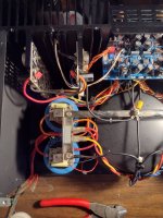
Next, I knew i wanted to get rid of the factory distribution block and upgrade the power cable. This comprised more work than any other single step, so keep that in mind when considering the utility of this modification.


Here is an idea of how much wiring is in this amp. I cut the entire distribution block out so that i could leave the wires on it and have a reference point of where everything goes.

This was tedious and time consuming, and a little nervewracking due to how short the wires are. Luckily none of it should ever need touched again. In case you were wondering like myself, the capacitor is a "spark killer" i just replaced it with one of oem specs, nothing fancy here.

Sidenote: you see that extra hole in the chassis with primer? I cleaned that off and repurposed it as a ground point for my new 3 prong cord. I used a 14/3 husky power tool cord from home depot.

Much less wiring going back in the amp. Here you can see Ive also installed a Hoppes earth loop breaker, and a pair of 50a bridge rectifiers
Next, I knew i wanted to get rid of the factory distribution block and upgrade the power cable. This comprised more work than any other single step, so keep that in mind when considering the utility of this modification.
Here is an idea of how much wiring is in this amp. I cut the entire distribution block out so that i could leave the wires on it and have a reference point of where everything goes.
This was tedious and time consuming, and a little nervewracking due to how short the wires are. Luckily none of it should ever need touched again. In case you were wondering like myself, the capacitor is a "spark killer" i just replaced it with one of oem specs, nothing fancy here.
Sidenote: you see that extra hole in the chassis with primer? I cleaned that off and repurposed it as a ground point for my new 3 prong cord. I used a 14/3 husky power tool cord from home depot.
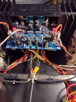
Much less wiring going back in the amp. Here you can see Ive also installed a Hoppes earth loop breaker, and a pair of 50a bridge rectifiers
Next was wiring in everything on the pcb. This part wasnt as scary as it seems. Hoppe has done a good job of labelling the input board to take any guesswork out of which wires go where. Things are much less cluttered without the ac wiring running across the amp, and with all of the boards wiring on the underside. Youll also note ive split the transformer ground wire and ran it to each bank of filter caps. Does this help with noise? I dont know, but its easy enough to do and every bit counts.

I came up with what i thought was an ingenious way of splicing the ground wire. I stripped the plastic off one of these bullet connectors. The big end is just the right size for a pair of 14 awg wires. Tin the wires, fill connector with flux, and melt em in. The joint was covered in shrinkwrap and I expect will last forever.

I came up with what i thought was an ingenious way of splicing the ground wire. I stripped the plastic off one of these bullet connectors. The big end is just the right size for a pair of 14 awg wires. Tin the wires, fill connector with flux, and melt em in. The joint was covered in shrinkwrap and I expect will last forever.
Attachments

First startup. After double checking all of the wiring, i plugged it in and turned it on. Nothing crazy happened, everything seems ok. Immediately I start with bias. Left side is at 0mv, and the right side was much too high, around 70 mv. I could hear the transistors at that level. Quickly i brought it back down to about 8mv and matched the other side. If you do this on your amp, turn your bias pots fully counterclockwise before first startup to prevent over bias.
Then I measured the dc offset. Left side is at 4mv, but there is something wrong with the right side. Its reading 100 mv. Hmm... Well, ill have to look at that input pcb again. Maybe it has something to do with that high initial bias.
Since the amp is at least stable, i decided to go ahead and test channel matching (flawless) and burn it in to set bias using my sacrificial test speakers.
After a while i got the bias dialed in and the dc offset in the bad channel settled down to about 60mv. At this point i know something needs fixing. But theres nothing i can do about it now, and its not hurting my speakers, so I threw it in my system. I cant hear any difference between the 2 channels and this thing sounds fantastic. Whatever the problem is, its not affecting sound delivery. Definitely made for a bittersweet finale to 2 full days work on the amp
Hey, nice work!
Your offset might be due to some flux residue, I suggest an ultrasonic cleaner and ethanol.
One your transformer connections, the third wire that goes to the center star-ground is unnecessary. The arrangement you have with the two separate transformer ground wires, one to each capacitor bank, is optimal because it keeps the charging pulses away from the star-ground.
Thank you, im pretty happy with how it turned out!
I used a water soluble flux and cleaned the board completely after assembly, but there certainly could be a flux issue from when i soldered in all the wires. Any ideas on cleaning after its installed in the amp?
Its hard to tell in those pictures, but the "3rd wire" is actually going to one of your earth loop breakers mounted to the chassis between the transformer and right side power caps
- Home
- Amplifiers
- Solid State
- Adcom GFA 555 MK II Restoration project