This project is inspired by the wonderful headphone amp by mediatechnology using a THAT1646 line driver in a novel way.
https://www.diyaudio.com/community/threads/simple-class-a-headphone-amp-using-that1646.163544/
You can buy the "Dual Class-A II Output" (DCAO2)" headphone amp here
https://ka-electronics.com/shop/index.php?route=product/product&product_id=67
This new project aims to design a small mono SMD version of the above amplifier in a balanced bridge configuration.
In addtion I will add a small signal peak detect to drive an external LED and maybe a delayed power-up to the opamp power rails to prevent power-on damage to the phones. First draft incoming.
Last edited:
First draft. Comments welcomed.
Layout and values are WIP.
Generally 1206 for easier hand soldering.
C0G and X7R bypass are 0805 though for lower series inductance.
Peak detect header for remote LED.
2% matched pair transistors in SOT-26
DMMT5551 https://www.diodes.com/assets/Datasheets/ds30436.pdf
DMMT5401 https://www.diodes.com/assets/Datasheets/ds30437.pdf
Last edited:
If you add the 47 uF back across the Vbe multipliers as shown in the original you will have turn-on delay.
Here is a simple peak flasher you can make with a TL431: https://proaudiodesignforum.com/forum/php/viewtopic.php?f=6&t=960
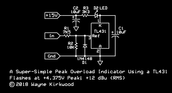
I would sample the output with the peak flasher rather than the output from the line receiver. You set the threshold with the value of R1.
BTW you might want to correct your text which shows "THAT1686."
Here is a simple peak flasher you can make with a TL431: https://proaudiodesignforum.com/forum/php/viewtopic.php?f=6&t=960
I would sample the output with the peak flasher rather than the output from the line receiver. You set the threshold with the value of R1.
BTW you might want to correct your text which shows "THAT1686."

Looking nice but why balanced and why choose 4x tiny parallel output pairs instead of a single SOT-89-pair or so?
(up to TO-263)
I´d even go through-hole on a single output pair although I love SMD but this way the amp is more versatile
(thinking insensitive headphones like Hifiman or desktop speakers; either no heatsink, little heatsink or bolt to aluminium/heatsink)
(up to TO-263)
I´d even go through-hole on a single output pair although I love SMD but this way the amp is more versatile
(thinking insensitive headphones like Hifiman or desktop speakers; either no heatsink, little heatsink or bolt to aluminium/heatsink)
How much output power do you need?
I think you may have difficulty heatsinking this.
If it were me I'd continue with SMT for the pre-driver but use leaded output devices (BD139/140) bolted to metal.
Note that the Vbe multiplier needs to be in thermal contact with the outputs.
I think you may have difficulty heatsinking this.
If it were me I'd continue with SMT for the pre-driver but use leaded output devices (BD139/140) bolted to metal.
Note that the Vbe multiplier needs to be in thermal contact with the outputs.
Thanks!How much output power do you need?
I think you may have difficulty heatsinking this.
If it were me I'd continue with SMT for the pre-driver but use leaded output devices (BD139/140) bolted to metal.
Note that the Vbe multiplier needs to be in thermal contact with the outputs.
Worst case - the HF10AK compression driver requires ~ 1 Watt @ 1m for 108dB / 600 to 20kHz.
4 meter listening position with 20dB headroom
76dB = 10 mW
96dB = 1 W
Last edited:
@joensd
I could back-to-back TO264 MJL1302AG / MJL3281AG or similar. This would allow for a "slimline heatsink" metal casing.
Alternatively TO252 such as the 2SA2039/2SC5706 with plenty of vias to a 4 layer board along with some holes toPerhaps a heatink casing pressed against their top sides.


I could back-to-back TO264 MJL1302AG / MJL3281AG or similar. This would allow for a "slimline heatsink" metal casing.
Alternatively TO252 such as the 2SA2039/2SC5706 with plenty of vias to a 4 layer board along with some holes toPerhaps a heatink casing pressed against their top sides.
Last edited:
I've used these before to transfer heat to a screw hole or to the bottom gnd plane. A surface mounted Vbe multiplier could be thermally connected to the bottom and top pours in this way.
https://ims-resistors.com/wp-content/uploads/2020/11/ThermaBridge_VersionD_202010.pdf
https://ims-resistors.com/wp-content/uploads/2020/11/ThermaBridge_VersionD_202010.pdf
Last edited:
For example. Six ThermaBridge devices on the right transfer just heat from the collector tabs to the chassis ground plane & mounting holes.I've used these before to transfer heat to a screw hole or to the bottom gnd plane. A surface mounted Vbe multiplier could be thermally connected to the bottom and top pours in this way.
https://ims-resistors.com/wp-content/uploads/2020/11/ThermaBridge_VersionD_202010.pdf
Now, that´s a cool idea. Might not be too service-friendly but unique and compact nevertheless.I could back-to-back TO264 MJL1302AG / MJL3281AG or similar. This would allow for a "slimline heatsink" metal casing.
Thermal vias can go a long way if properly done. For 1W output or little above you´ll probably be fine as is. (meaning the TO-252 version)
Simulate what kind of dissipation you will expect per device, then you know if you need further changes.
The transistors could be moved to the edge of the board. This way you could use a gap/thermal-pad underneath the board and couple the thermal path to solid metal but that´s probably not even needed.
Will follow with interest. "Just" finished an amp for my compression drivers which is a buffer only.
(used lineup´s 4W amp so far but looking for something smaller)
A slight departure today. I present the humble beginnings of "QuadThatMono"
I'm now using four THAT1646 devices to drive four complementary pairs. The outputs from each THAT1646 are length matched to each transistor pair. On the front end we have THAT128x as "double-balanced cross-coupled" input. That's more Wayne Kirkwood inspiraton! ( @mediatechnology ) See fig4 from his 2013 article. https://www.edn.com/audio-line-receiver-impedance-balancing-using-a-2nd-diff-amp/ Using the front end approach mentioned above a simple switch allows to select polarity of the signal from the front end THAT128x into the THAT1646 drivers.
The usual LM317/337 pair with 22uF caps on the adjust pins for supplying the amps.
Use of copper large pours over 4 layers with 0.5mm vias should help dissipate heat.
ThermaBridge ceramics disccused above will also shunt heat from top planes to the mounting screw holes.
2 watt resisitors (wide 1218 package) to minimise trace inductance to the OUT plane.
2 watt & 100n MKT to gnd
Simulates well and tracks the noise and SNR floors of the THAT128x front end. I'll share that file shortly.
Last edited:
Taking shape. I've switched to using 3 or 4 parallel 750mW 1210 resistors to reduce inductanaces. Somewhat cheaper that specialised wide packages. The board is currently 120x60mm.
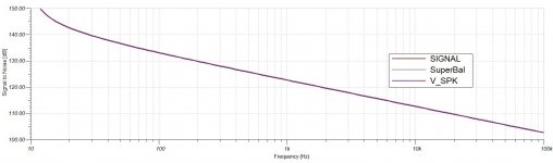
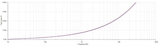
On each power rail there will be a 1R + 1000uF FT, 33uF ZA and 4.7uF X7R. I will provide rail impedance charts tommorrow.
Working on the bias circuits next.

On each power rail there will be a 1R + 1000uF FT, 33uF ZA and 4.7uF X7R. I will provide rail impedance charts tommorrow.
Working on the bias circuits next.
Last edited:
It sure helps spreading the heat at first but I wouldn´t want to rely on inner layers at all:Use of copper large pours over 4 layers with 0.5mm vias should help dissipate heat.
This would keep heat trapped inside the PCB and you want it to go "ambient" primarily.
Top and bottom layers will radiate enough heat into the intermediate layers without direct connection.
Not sure why LEDs (esp. ceramic) would improve thermals other than adding heat themselves but why not place some if you like that glow.
I can see you´re going for an aesthetically pleasing PCB which is nice. Hey, aren´t you the guy/gal that made this speaker with the beautiful waveguide in the front baffle?
You should confirm the power dissipations of each transistor and resistor (+total) in the sim whilst you are at it.I believe these figures are about right.
8 ohm compression driver
1W = 3.83V and 353mA
3W = 4.9V and 613mA
Seems a lot but you might have already determined that correctly!?3 or 4 parallel 750mW 1210 resistors
This could be a nice twist to your board and future proof it as tweeter amp.or maybe add a small header to route that off to an optional small "crossover board"
If you can make a header with VDD/VEE/GND/Vin/Vout and then place a couple of passives plus opamps on the extra board.
Of course you can also use discrete buffers like a simple FET buffer or a diamond buffer like I used here:
Active discrete XO
I would try to squeeze a 12dB filter on the main PCB and avoid the extra board. Make the filter easy to "bypass" if you do.
Last edited:
All good points and noted!It sure helps spreading the heat at first but I wouldn´t want to rely on inner layers at all:
This would keep heat trapped inside the PCB and you want it to go "ambient" primarily.
Top and bottom layers will radiate enough heat into the intermediate layers without direct connection.
Not sure why LEDs (esp. ceramic) would improve thermals other than adding heat themselves but why not place some if you like that glow.
I can see you´re going for an aesthetically pleasing PCB which is nice. Hey, aren´t you the guy/gal that made this speaker with the beautiful waveguide in the front baffle?
You should confirm the power dissipations of each transistor and resistor (+total) in the sim whilst you are at it.
Seems a lot but you might have already determined that correctly!?
This could be a nice twist to your board and future proof it as tweeter amp.
If you can make a header with VDD/VEE/GND/Vin/Vout and then place a couple of passives plus opamps on the extra board.
Of course you can also use discrete buffers like a simple FET buffer or a diamond buffer like I used here:
Active discrete XO
I would try to squeeze a 12dB filter on the main PCB and avoid the extra board. Make the filter easy to "bypass" if you do.
Ceramic LED close to the power stage could be used for thermal / Vbe feedback.
Here’s my speaker project!
https://www.diyaudio.com/community/threads/ath4-waveguide-inspired-multi-way.384410/
https://www.diyaudio.com/community/threads/ath4-waveguide-inspired-multi-way.384410/
- Home
- Amplifiers
- Headphone Systems
- SMD Class A Headphone Amp (THAT1646)