I'll use Vishay ThermaWick to transfer heat from the transistors to the chassis gnd pour & mouting holes. https://www.mouser.co.uk/datasheet/2/427/VISH_S_A0010295278_1-2571075.pdf
Added
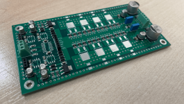
1). ThermaWick to transfer heat to the outer copper pours on top and bottom layers. These wick heat out to the four mounting holes (chassis gnd) too.
2). 6pin header to access input signal before it connects to the THAT1646s. Allows for "crossover boards" or additional filtering here. Both polarities exposed from the "SuperBal" input on the header.
3). Headers for offboard Vbe sensor boards.


I would make provisions to also use a DRV134.
The DRV134 requires a voltage divider between the Vbe multiplier and pin 4 because it has a differential gain of "4" versus a gain of "2" for the 1646.
The DRV134 has better clipping behavior in the "common mode drive" configuration.
The 1646 is an excellent line driver in its "normal" application and a great headphone amp for mid-to-high sensitivity headphones but in an application in which it might clip, such as this one, I think you'll be happier with the DRV134.
When I was making headphone amps with this topology I built mine with DRV134s. My current headphone amp, the DCAO-II, uses op amps to emulate the 1646/DRV134.
The peak current you'll need will require a high Iq to maintain class-A. I honestly don't think you'll be able to get the heat out. My 10W amp used massive heatsinks.
I would also put the Vbe multiplier sense transistor in the middle of the output array and use the same type/geometry.
Last edited:
I would make provisions to also use a DRV134.
The DRV134 requires a voltage divider between the Vbe multiplier and pin 4 because it has a differential gain of "4" versus a gain of "2" for the 1646.
The DRV134 has better clipping behavior in the "common mode drive" configuration.
The 1646 is an excellent line driver in its "normal" application and a great headphone amp for mid-to-high sensitivity headphones but in an application in which it might clip, such as this one, I think you'll be happier with the DRV134.
When I was making headphone amps with this topology I built mine with DRV134s. My current headphone amp, the DCAO-II, uses op amps to emulate the 1646/DRV134.
The peak current you'll need will require a high Iq to maintain class-A. I honestly don't think you'll be able to get the heat out. My 10W amp used massive heatsinks.
I would also put the Vbe multiplier sense transistor in the middle of the output array and use the same type/geometry.
Thanks for the input! I’ve just finished the crossover sub board. It’s a high pass with a shelving filter and a notch - two OPA1602 parts. I have a plan for the heat. 😁
https://www.3m.co.uk/3M/en_GB/novec-uk/applications/immersion-cooling/
I’ve also made provision in v2 for a screw down copper AMD Opteron 1U heat sink

Cool project! If you can make single layer board on aluminum IMS substrate, you can heatsink the whole PCB for massive dissipation. Use of 0R resistor jumpers may be needed to cross traces when going single layer. IMS boards cost the same as FRP boards now at JLCPCB. They even make them in green mask vs the ugly white usual IMS board masks. I have a Class A headphone output stage on aluminum now. Just bolt it to metal plate for good heatsinking.
Now that’s a plan!!Cool project! If you can make single layer board on aluminum IMS substrate, you can heatsink the whole PCB for massive dissipation. Use of 0R resistor jumpers may be needed to cross traces when going single layer. IMS boards cost the same as FRP boards now at JLCPCB. They even make them in green mask vs the ugly white usual IMS board masks. I have a Class A headphone output stage on aluminum now. Just bolt it to metal plate for good heatsinking.
Still waiting for my batch of THAT1646 from Mouser. Should be here Monday. In the mean time I'm working on the firmware for my little CS43131 board. Struggling with bits. https://www.diyaudio.com/community/...dual-mono-dac-on-a-dip-24.384692/post-7003911
Update. Almost finished v2.
The ThermalWicks worked well on V1. However heat was an issue afterall. I have now added through holes at each wick (chassis side) to allow screwing to board down to the heatsink.
The crossover board is nearlly done too.
More updates soon.

The ThermalWicks worked well on V1. However heat was an issue afterall. I have now added through holes at each wick (chassis side) to allow screwing to board down to the heatsink.
The crossover board is nearlly done too.
More updates soon.
Last edited:
I am closing in on a fairly good circuit now.
Here are my Tina Ti results with 1Vrms input into a 8 ohm load.
SUPERBAL is the output of a THAT1286 "Superbal" input circuit.


Here are my Tina Ti results with 1Vrms input into a 8 ohm load.
SUPERBAL is the output of a THAT1286 "Superbal" input circuit.
Thanks! I have a set of boards that await testing....Really glad to see more SMD in DIY!
I´m following your project!
Just have to add the 1286.Thanks! I have a set of boards that await testing....

This is very cool indeed! I was unaware of thermal jumpers until now 🙂
What was your final schematic?
What was your final schematic?
Yeah, they are a super good way to redirect heat to screw holes / chassis mounts.This is very cool indeed! I was unaware of thermal jumpers until now 🙂
I'll release final schematic once done and tested. I have a feeling my routing is pretty dire. Here's the quad DRV134 Tina-TI file. I think this was the latest.
Attachments
Last edited:
- Home
- Amplifiers
- Headphone Systems
- SMD Class A Headphone Amp (THAT1646)