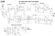
First here is the schematic.
Next here is the output
Questions.
1. With zero input and scope on output pins I see a huge voltage output off 20v peak to peak. The second I put any load across the output (Ear phones). The voltage drops to zero. What kind of load should be put across the output so I can test ?. A friend told me not to put any load. Another said 1K. Another said ear phones are ok. Is it normal for the output to behave like this with no load ?.
2. Playing with the gain control I can get a range of output.
Upstream of this pre-amp and tone control board I have a TDA7294 amp and also a LM3886 (Separate projects same pre amp). , So what voltage should I feed the upstream AMP ?. We tried feeding the amp a signal from my phone direct and the output was very disappointing. I read the data sheet for the TDA and LM multiple times but nowhere could I find a recommended input voltage. Am I blind / stupid or they expect you to know this ?.
3. Any ideas to improve or tweak this circuit ?. (Yes I know its an old design from the 50s.).
4. What could be causing the distortion on channel 2. (Blue line).
5. What is the safe upper limit on the input signal of this circuit. Various items will be hooked up to this input from CD/Bluetooth/Phone jack/MP3 player/Turn table
6. The bass and treble introduce a gain off upto 15 DB. How do I limit this to say only 6 DB.
Attachments
you build an occilatorFirst here is the schematic.
Next here is the output
Questions.
1. With zero input and scope on output pins I see a huge voltage output off 20v peak to peak. The second I put any load across the output (Ear phones). The voltage drops to zero. What kind of load should be put across the output so I can test ?. A friend told me not to put any load. Another said 1K. Another said ear phones are ok. Is it normal for the output to behave like this with no load ?.
2. Playing with the gain control I can get a range of output.
Upstream of this pre-amp and tone control board I have a TDA7294 amp and also a LM3886 (Separate projects same pre amp). , So what voltage should I feed the upstream AMP ?. We tried feeding the amp a signal from my phone direct and the output was very disappointing. I read the data sheet for the TDA and LM multiple times but nowhere could I find a recommended input voltage. Am I blind / stupid or they expect you to know this ?.
3. Any ideas to improve or tweak this circuit ?. (Yes I know its an old design from the 50s.).
4. What could be causing the distortion on channel 2. (Blue line).
5. What is the safe upper limit on the input signal of this circuit. Various items will be hooked up to this input from CD/Bluetooth/Phone jack/MP3 player/Turn table
6. The bass and treble introduce a gain off upto 15 DB. How do I limit this to say only 6 DB.
View attachment 1072275
") probably you need to add a capacitor somewhere..
probably you need to add a capacitor somewhere..Now I look at the schematic... Thats a weird way to have the gain control in the feedback loop? Could be the reason..you build an occilator
Max input voltage is usually max output voltage divided by gain of amp.I read the data sheet for the TDA and LM multiple times but nowhere could I find a recommended input voltage. Am I blind / stupid or they expect you to know this ?.
Dam I love you guys.
I was able to find answers for some of my questions.
1. To figure out the Freq being targeted by Tone and bass do the math for the RC Network. Between the cap used and the resistor. Have figured out how to do the math or use a RC network calculator. A little confused as to how to figure out the trim pot resistor value. But working on it. I've built RC networks for other circuits but never with a trim pot. Hence a little confusion.
2. A typical pre-amp puts out 2 volts to 6 volts (Found this on a car audio forum). A good range is 4-6 volts. Will continue to read up and study on quality preamps and what voltage they typically put out. STV thanks man what you say makes perfect sense.
3. To improve the overall quality of the sound and reduce noise. Use metal film 1% resistors. And experiment with various OpAmp IC some are better than others.
. Found this info on a guitar site. https://www.bassesbyleo.com/forum/viewtopic.php?f=28&t=2294
4. I would also like to add a Treble boost button and a bass boost button. Working on the values. And reading up.
Also a good read on tone control.
https://www.bassesbyleo.com/relative_tone.html
Working on figuring out the rest.
Thank you for your insights and help.
I built the Power supply board for my AMP. So its really clean. But the power section on this PCB is not really upto scratch. Im picking up radio or TV signals. With this.
Not my schematic or design just a DIY kit I purchased. It was one of the better boards sold in my country. I basically picked up all the Preamp and tone control boards sold in our country. This is one of the better ones so started to work on it.
Ps: The distortion issue has been cleared up. I replaced the china made NE Chips with some new chips I sourced from digikey. I also stopped using my phone as a function generator and instead hooked it up to a dedicated function generator.
Ps: 2 safe input signal I figured out by measuring my various inputs.
My Phone Audio jack gives me a max output of 0-1 Volt. My Blue tooth module gives me an output off about 0-.5 volts. My MM turntable gives me an output off about 0.4 volt.
Hence I have set the output of my function generator to 0.8 volts and then tuning from there on out. Im trying to get the pre-amp tone board to give me about 4 - 6 volts. Out into the amp.
Last edited:
So 100 nf between pins 4 and 8. Or 100 nf between Pin4 to ground and Pin 8 to ground.Use 100nF caps to ground as near to the pwr supply pins of each NE5532. It’s common practice, but I didn’t notice them in your scheme.
I will scan some other pre-amp circuits to understand what your saying. This board has 4 NE Ics to Im looking at adding at least 8 100nf caps. (Get what your saying just wondering what would happen if I put a 100 Nf between pins 4 and 8. VIn+ and Vin-.
Also read that a RF filter on the input pins would reduce noise. So 1K and 220pf on both the input pins would help ?. Again I need to study other circuits for ideas.
Read this on another forum:
I've always wondered why there is no decoupling cap (100nF ceramic) across the power pins of the opamp. While the opamps used in this pre are not high bandwidth and thus not very prone to parasitic oscillation with suboptimal supply impedance it would still be common engineering practice to have some decoupling installed, just in case. (Hence my doubt about putting the 100nf across power pins I could only find pin 4 and 8 as the power pins on the NE.
Last edited:
a good read for people like me getting started with tone control boards.
https://www.electricaltechnology.org/2019/08/active-high-pass-filter.html
https://www.electricaltechnology.org/2019/08/active-high-pass-filter.html
After days of reading up.
There is a wealth of info on this forum covering this and other tone control boards. As well as hundreds of pages discussing swaping out the NE for a better more modern Op-Amp.
A popular recommendation is to
Use this project
https://sound-au.com/project97.htm
So I have opted to scrap this project and plan to just build Project 97.
One point I am still confused about. The 100Nf decoupling cap. For pins 4 and 8. Is it between pins 4 to ground and 8 to ground or just between pins 4 and 8. Reading this has just resulted in more confusion.
https://www.eetimes.com/op-amps-in-small-signal-audio-design-part-3-selecting-the-right-op-amp/
For now I have just added it to the output of the +15 and -15 regulator ICs. And ground. After all these rails are what eventually feed the NEs.
I did try installing them between pins 4 and 8 on the NE but this caused a short.
Google of Peter J Baxandall tone control also threw up a wealth of info.
This concept was First published in Wireless World in 1952.
Edit found my answer.
https://forum.allaboutcircuits.com/...ing-capacitors-for-op-amp-in-dual-rail.20220/
Last edited:
So I have changed all the NE Chips, Changed all the caps to top brand. Added all the decoupling caps. Across the power of each NE.
Yet I am getting this output signal with nothing hooked up. Have not been able to clean it up.
Plan for today. Is to short the input lines. And try again. And then to input a low voltage signal and try again.
The circuit has 4 NEs. So its almost like each NE is contributing one wave. Cant think of anything else.
4 volts peak to peak with gain at 40% is going to be a problem. I did try shorting the input pins but still getting this output.
The problem is with RV3 and RV4. I see no value marked on the schematic. You need to limit the range these two gain controls have so I would recommend you add a series resistor between the 220uF and the pot. The value should be 0ne tenth the pot value. This will limit the gain to 10 times.
P.S. The design is not from the 50s. The NE5532 first appeared in the 70s.
Cheers
Ian
P.S. The design is not from the 50s. The NE5532 first appeared in the 70s.
Cheers
Ian
Now I look at the schematic... Thats a weird way to have the gain control in the feedback loop? Could be the reason..
The problem is with RV3 and RV4. I see no value marked on the schematic. You need to limit the range these two gain controls have so I would recommend you add a series resistor between the 220uF and the pot. The value should be 0ne tenth the pot value. This will limit the gain to 10 times.
P.S. The design is not from the 50s. The NE5532 first appeared in the 70s.
Cheers
Ian
The active volume control part of the circuit is a direct copy from Doug Self's precision Preamp of 1996. The volume control should be a 10k linear pot.
Typical practice is to use a 100nF cap on each opamp supply pin, other cap lead grounded. Use ceramic caps (X7R dielectric) with lead length as short as is practical.
I agree with comments that volume pot design is unusual. The tone control stage inverts, so that probably motivated design of an output stage that also inverts to yield net non-inverting behavior.
It might be useful to know volume pot resistance. With power off, you should be able to measure pot resistance in circuit with a multimeter. To determine the pot's resistance taper, would you also set pot to 50% rotation and report resistance between wiper and each end?
I assume with power off, there's no evidence of the offending signal? i.e. no external RF interference? With inputs shorted, does the output signal change with pot rotation? If oscillation persists independent of rotation, I suggest a diagnostic experiment: use your scope probe to establish a short between U5A pins 1 and 2. This configures the opamp as a unity gain follower and should be stable. That is, trace should go to 0V and be clean. Be sure to use X10 scope probes to avoid provoking oscillation. Any interesting changes?
Last edited:
With no power there is no output. In fact as soon as i hooked up my function generator to the input the output dropped flat.
As of today This is the best signal I could get so far. With bass and treble turned all the way down.
The pot Rv3 Rv4 is 10k. At half way the input and output both both give the same voltage I.e. 1 volt in = 1 distorted volt out. Taking it up to 70% gives me what I want which is 1 volt in and 5 volts out. Have given up trying to get a clean signal with no input and now just trying to get the circuit to work. yellow is 1 volt in @ 1kh
Blue is output.
Thanks for the reference I will chk the book.
Last edited:
Well it looks triggered now, that's good.
But you have what looks like an oscillation. Do you still see the oscillation if you turn down the input signal level to zero?
Just to be sure, check that the function generator is clean, connect it to the scope directly and check for a clean signal. Step by step is the word!
Jan
But you have what looks like an oscillation. Do you still see the oscillation if you turn down the input signal level to zero?
Just to be sure, check that the function generator is clean, connect it to the scope directly and check for a clean signal. Step by step is the word!
Jan
With no power to my function generator or my board I get this then again I don't trust this scope that much may need to get my fluke out of storeage and chk with that.
@jan the function generator signal is allways squeky clean from 100 mili volt to 9 volts. The oscillations remain even with zero volume

@jan the function generator signal is allways squeky clean from 100 mili volt to 9 volts. The oscillations remain even with zero volume
Sorry can't edit post but problem resolved went step by step found u4 to be culprit changed it and its all clean now. Fake chips are a huge problem in some markets. This is my first ne board and its been a good learning experience. I suspected the 15 volt regulator because one power rail was very different from the other.
What I learned from this is that TI chips are more often cloned i.e. they stamp the fakes with TI. A fairchild chip is less likely to be faked. The logo looks like a V.
What I learned from this is that TI chips are more often cloned i.e. they stamp the fakes with TI. A fairchild chip is less likely to be faked. The logo looks like a V.
Last edited:
Self lays the blame at Baxandall, Wireless World Nov 1980. Large parts of that chapter are essentially restatements of Baxandall. That paper is worth reading to death.The active volume control part of the circuit is a direct copy from Doug Self's precision Preamp of 1996.
- Home
- Amplifiers
- Chip Amps
- NE5532 preamp questions.