a - well done!Sorry can't edit post but problem resolved went step by step found u4 to be culprit changed it and its all clean now. Fake chips are a huge problem in some markets. This is my first ne board and its been a good learning experience. I suspected the 15 volt regulator because one power rail was very different from the other.
What I learned from this is that TI chips are more often cloned i.e. they stamp the fakes with TI. A fairchild chip is less likely to be faked. The logo looks like a V.
b - always buy from a reputable source!
Jan
Thank you. So far this is the best Tone control board. I own. Vs the ebay / chinar / other preamp and tone control boards on the market. So I plan to work on this and make it useable. One advantage it has over the Ebay / China boards with only two NE ICs. Is that it has a gain control. While those dont and I have seen them putting out in excess of 20 volts and no way to easily control the gain. I would need to play around with some resistor values. Based on other threads and people who have faced this problem. Where as on this board I can set my gain to 60-70% and Im done.
There is one problem which is driving me mad. Why is it that my negative voltage rail is 14 volts where as my positive rail is spot on 15. I even tried replacing the regulators. My Transformer puts out a 15-0-15 1 AMP tap. Which shows up at 19 volts as input to the 7915 and 7815 regulators. Till the input pins they are both equal but once out the regulator the negative voltage rail drops. 4 NE ICs should be more than happy with 1 AMP.
Only logical though I can have is that there is a higher load on the negative rail for some reason. Have tried removing all the NEs and I still see this mismatch.
As a side note I noticed this on my Akai amp also which puts out 42 volts d/c on the positive and 39-40 on the negative.
I have one request. Do you really think Project 97 would work better. I have two options I can try and build project 97. Or I can try and build a Parametric Equalizer. https://sound-au.com/project97.htm
I do plan to test this circuit with the LM4562 IC also. Have a list of ICs which are plug in compatible with the NE and plan to test each of them.
Test for sound quality and THD.
The trim pots on this project are 47K volume, 100K for Bass and Treble. The gain trims are 10K.
I guess you earned those bragging rights. But you must understand every single day people new to audio are joining starting from zero. And they count on the experience and wealth of knowledge of the seniors to guide them.
If you visit the sellers page he says the same thing nothing new here.
You have to appreciate the fact that an old dog like me is willing to start from scratch and put the time and effort into learning a new field just for the joy of learning.

I didn't mean it as a slight on newbies and those just starting out 🙂 more that designers of the past had many of these circuit configurations all figured out back in the 60's and 70'sguess you earned those bragging rights. But you must understand every single day people new to audio are joining starting from zero.
The latest and greatest analogue designs of today all use those same sub circuits and techniques as building blocks.
Ive been able to get by with just making digital circuits. Like automotive ECUsI didn't mean it as a slight on newbies and those just starting out 🙂 more that designers of the past had many of these circuit configurations all figured out back in the 60's and 70's
The latest and greatest analogue designs of today all use those same sub circuits and techniques as building blocks.
Analogue skills is very rare and hard to comeby these days.
Most of the new gen digital kids are in awe of people with analogue skills. As I am.
For sure its a totally different world in itself. Its such a vast ocean of knowledge. Its easy to spend a lifetime in it and still keep learning.
For me its been a few months since I got started. And this place is such a superb resource. Ive spent days just going thru the old posts.
Right now Im a bit depressed. After spending days on this and finally getting a clean signal. That joy was very short lived because the second I adjusted the knobs for treble and bass the distortion was back. Now I am down to trying different things that give me the cleanest possible signal across the widest possible range of kob movement. Then document the values where they start and end.
On either extremes of treble or bass the signal is always clean. But some where mid point there is a band of 30-40% where the distortions return.
These ranges of clean and distorted change based on which companies NE is used.
Have placed an order for a fresh batch of NEs. From Element14. Lets see how it goes.
Finding a good source for your components in my country is an art form in itself. And takes a few years to line up.
Today Im going to jump back to the Ebay / AliExpress two NE Preamps and tone control boards and see if they have the same problem. If they dont then I will study their tone control circuits and compare it to this ones. Another idea is to create a simulation model for all these circuits. That's how I normally work. First in the simulator. Then in the real world. Another thing to try would be to remove all the decoupling caps I added. And take this back to stock. And see if that helps. One more option would be to mount all the controls directly to the PCB. Even though I am using shielded wire it could be the culprit. Last option would be to try a ferrite bead on the input. Funny thing I spent the last 20 years of my life dealing with high voltage output circuits (Ignition) and over coming the problems they create. And now Im stuck at the opposite end of the spectrum trying to deal with low voltage signals and the problems they create.
I would begin by checking some basics. Use the scope to check the rails are clean as measured at the all the opamp pins (4 and 8).
Use the common ground point in the power supply as the ground reference for the scope.
Also check with the scope that the ground points such as pin 3 and 5 of U4 are clean.
If you have doubts over the opamps then stick something else in there such as 4558's or TL072 or TL082 as a test. They will all work just fine.
When the problem is occurring do a quick check on the outputs of U7 (the input buffers) to make sure that the output is still clean. If that is OK then check the output of U4a and U4b to make sure the issue is tone control related and not the active volume stage causing a problem.
Also check there is no DC offset occurring on any of the opamp output pins. They should be close to zero volts DC on a DVM and a scope should show no significant shift in the trace (DC coupling for the scope).
Thanks I have picked up a few of those boards. My testing today shows little or no distortion in the wave form of these boards. I only had a minor jitter with the bass turned up all the way. This was the Salcon board. It uses a Zener no voltage regulator IC to limit the power to 12-0-12.
Turning any of the controle seem to act like volume keys. This board had Bass / Mid / Treble / Unlike the earlier board being discussed which only has Bass and Treble. The wave form does shift though but it does not go fully inverted.
I will go back to working on the first board and try and solve this mystery. Mooly has given me a road map of steps to take which I will try.
Worst case I know I have one tone control board that works. But Id really like to sort out the first board. Once I get it to work. I plan to add some parts to the existing schematic that will give me Mid control also.
Another thing I dont understand is say I am sending in a 60hz signal. So turning the High / Mid knobs should not impact it right ?. Because its a low freq signal. Only the bass knob should impact it. But no matter Hz signal I feed it is impacted by all the knobs this makes no sense to me.
One would think Bass should only impact the low freqs. Mid and High should only impact the mid and high frequencies.
Thanks Mooly after diner I will spend a few hours trying what you have said.
My understanding of electronics is very rudimentary. But may be the tone controls are based on vintage Quad 34 Preamplifier 'tilt' controls, where the turn of the control not only increases bass but lowers treble or vice versa. Kind of like seesaw. Or may be circuit design may be flawed or reverse connection of controls ?<snip> Another thing I dont understand is say I am sending in a 60hz signal. So turning the High / Mid knobs should not impact it right ?. <snip>
regds.
I found these videos to be very helpful. There are many more videos some better. But this one kinda covers all the basics. It was a big help in getting me up to speed on how Op Amps work.
https://www.youtube.com/playlist?list=PLwjK_iyK4LLDBB1E9MFbxGCEnmMMOAXOH
https://www.youtube.com/playlist?list=PLwjK_iyK4LLDBB1E9MFbxGCEnmMMOAXOH
Another thing I dont understand is say I am sending in a 60hz signal. So turning the High / Mid knobs should not impact it right ?. Because its a low freq signal. Only the bass knob should impact it. But no matter Hz signal I feed it is impacted by all the knobs this makes no sense to me.
The response curves are always gradual but 60 Hz input should not be influenced by the treble control at all. Something sounds to be wrong with the way you have it wired/constructed if what you say is happening.
I've simulated the circuit and it behaves as expected really.

This shows max bass boost. You can see by the time you get to 10kHz there is no effect.

This is max treble boost. No effect as 60Hz.
The cut responses are mirror images.

Attachments
Sorry guys been down with the Flu.
Have not given up on this. Today is the first day Im feeling better. No fever.
I spent a few days trying to enter this up in the simulator almost done.
Im also very OCD about something not working so the positive and negative rails not having the same values was driving me mad. After replacing every part multiple times and it still not working. I handed the circuit over to my mentor for help.
He spent some time on the circuit and his conclusion is the datasheet for the regulator IC says 4% variation in power output so we are never going to get the rail voltages to match using this approach. Which is probably why so many Preamp and tone control boards use Zener Diodes to control voltage on these boards i.e. the Salcon Board has no regulator and it maintains an even 12 volts on both rails using just a zener.
Mooly I will chk out what simulator your using and try to use the same. .
I normally use Proteus but have never used speakers or anything Audio. So am having some problems with the simulation of audio.
Will just switch to some open source simulator it would make things simpler.
Also want to build a small PCB that will allow me to stress test each OpAMP. As of now total confusion. Watching the how to test your NE with a diode tester video. As per those tests all my NEs are fake. So really want a jig that can test each NE or any op amp I pan to use. Once I know the Opamp is to spec level of confusion will go down.
My mentor spent some time showing me how to use the FFT function of the scope to see the how the tone control board is working. And how I could test the board using the FFT function.
Ps: Noticed you used a 10K trimpot in your simulation. I suspect my using 100K trimpot could be part of the problem. Because there are ranges where it works just fine and then there are ranges where it all goes for a toss. Maybe I should try with a 10K trim pot. Or get it working in the simulator and see how changing the trim pots impacts its working.
Last edited:
If you are interested in the old way of looking at op amps, this is a gold mine. Beware of the math, though😎https://ocw.mit.edu/courses/res-6-0...ms-spring-2013/video_galleries/course-videos/
I gave up on trying to fix my pre-amps. Instead I just kept buying every board on the market. And testing them one by one.
I finally found what I was looking for a Pre-amp that did not create oscillations in the output.
Have spent the last month looking for scope traces from output off pre-amps and tone control boards and have not had much luck. Wonder why.
I got a high end Parametric Eq. I got a very basic tone control. The most basic board worked with zero distortion.
Now im trying to infer what makes one unit work clean and the other not.
What I came up with is.
1. The one that works the best does not use a voltage regulator it uses a Zener Diode.
2. The one that works the best uses original NE opamps not china made junk opamp.
What I plan next is to put the china op amp on the working circuit and see if it still works clean this would eliminate the op amp.
Next test would be to pull the 7812 and 7912 regulators and configure the power to be just a zener and resistor.
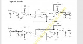
Here is the circuit that just works. Like most circuits sold in my country they are just copies of pre-existing stuff.
The circuit being discused here. If I turn the bass and trebel all the way down. It outputs a clean signal.
The second I try to add some trebel or bass. The wave form goes thick. If you zoom in on the curve. You see its made of a lot of small zigzag waves.
Is this how tone control works ?. Or should the wave form be clean at all settings ?.
Below is the circuit that just works. The opamp used is a NE not the number on the circuit.
I finally found what I was looking for a Pre-amp that did not create oscillations in the output.
Have spent the last month looking for scope traces from output off pre-amps and tone control boards and have not had much luck. Wonder why.
I got a high end Parametric Eq. I got a very basic tone control. The most basic board worked with zero distortion.
Now im trying to infer what makes one unit work clean and the other not.
What I came up with is.
1. The one that works the best does not use a voltage regulator it uses a Zener Diode.
2. The one that works the best uses original NE opamps not china made junk opamp.
What I plan next is to put the china op amp on the working circuit and see if it still works clean this would eliminate the op amp.
Next test would be to pull the 7812 and 7912 regulators and configure the power to be just a zener and resistor.
Here is the circuit that just works. Like most circuits sold in my country they are just copies of pre-existing stuff.
The circuit being discused here. If I turn the bass and trebel all the way down. It outputs a clean signal.
The second I try to add some trebel or bass. The wave form goes thick. If you zoom in on the curve. You see its made of a lot of small zigzag waves.
Is this how tone control works ?. Or should the wave form be clean at all settings ?.
Below is the circuit that just works. The opamp used is a NE not the number on the circuit.
Attachments
The wave should be clean at all times. If you use a sine to test the amplitude will change as you turn the controls but that is all, and that is frequency dependent. If you test with a squarewave then the leading and trailing edges will either show a peak or show a slow rise time again depending on frequency. With the controls centred a squarewave should pass through unchanged.
Whatever is going on with your circuits, it certainly isn't something typical or common. Opamp tone controls are universal and well behaved.
Whatever is going on with your circuits, it certainly isn't something typical or common. Opamp tone controls are universal and well behaved.
Thank you so much Mooly I finally understood what you were saying when I studied the one and only working op amp I have.
No matter what I do with the controls the signal does not break out in oscillations. I has amazing bass. And works well.
It was the cheapest and simplest of all the pre-amp tone control boards I have purchased.
So life pulled me away from my new hobby for a few months.
A 3rd option given a friend who is into audio was that Tone Control board design can cause oscillations.
As in a defective or poorly laid out board.
My present obsession is to build a test gig where I can throw on an opamp IC and put it thru its paces to confirm that there is nothing wrong with the opamp.
Im trying to read up on various ways to test op amps. So far the only one I could understand was that you pass it a sware wave and chk the raise time on a scope.
I have also started reading up on old posts on this forum. Where the subject of how to test an NE or any op amp can be done. Have also been buying op amp ICs from various vendors in the hope that I can get something that works the best.
Id like to develop this test gig on a bread board.
If anybody has any ideas on a circuit to test things like amplification (With two trim pots). Slew rate, and other parameters to test for.

It is very difficult to fully test an opamp but tbh you shouldn't really need to on a diy basis. They are super reliable and consistent provided you only ever buy from recognised authorised suppliers. There are so many fake products out there with devices being remarked to appear as something else.Im trying to read up on various ways to test op amps. So far the only one I could understand was that you pass it a sware wave and chk the raise time on a scope.
Pleased to hear you have it all working now 🙂
Only got one unit to work. Or rather only one of the boards worked fine from the day I got it.It is very difficult to fully test an opamp but tbh you shouldn't really need to on a diy basis. They are super reliable and consistent provided you only ever buy from recognised authorised suppliers. There are so many fake products out there with devices being remarked to appear as something else.
Pleased to hear you have it all working now 🙂
Had this brain wave last night. Why not make the one board that works my test gig.
i.e. just put any new op-amps I get onto this board. If it works its a pass. If it a fail it goes in the bin.
This helps me eliminate any doubts I have on the opamp. Once I have eliminated this doubt. The next would be to try swapping components or matching component values from the working board onto the non working boards. If this also does not solve the problem. Then the PCB layout is defective.
I think part of hte problem with most of the budget boards in the market is that they are all being thrown together on free PCB layout software on a web page of Easy PCB or some china site. These systems can never match the quality or DRC rules of a real layout program. Hence why so many of the designs are such a hit and a miss. I guess a pro with decades of exp could get a working board off one of these china web pages. But not your average enthusiast.
My friend says Im am on a fools errand and that as long as it sounds ok I should ignore all other issues. The thing is I do not trust my own ears. And I want to see a clean signal on the scope. Pretty much every branded amp I have tested from any of the big name brands never have any oscillation. So why should the system I use have it. This is all being done for the joy of learning something new. Nothing else. Will keep you posted if I catch the culprit for the oscillations.
There are two basic kinds of osilations I am fighting.
One is where the wave gets replicated i.e. each wave turns into 5-6 new waves like a ringing. The other is each wave gets really thick and if you zoom in you see its made up a series of smaller waves. Not sure what the technical terms for this is but I can take pics of the scope of each kind.
- Home
- Amplifiers
- Chip Amps
- NE5532 preamp questions.