For Sale Pioneer/TAD PT-R7iii Beryllium Ribbon Super Tweeters

1pair Pioneer PT-R7iii Beryllium Ribbon Alnico Magnet Super Tweeters
In original boxes, one is missing the foam gasket and hardware kit.
$950 for the pair
Shipping negotiable world-wide

Attachments

  • PXL_20221114_222412128.jpg
    PXL_20221114_222412128.jpg
    536 KB · Views: 125
  • PXL_20221114_222522236.jpg
    PXL_20221114_222522236.jpg
    348.4 KB · Views: 97
  • PXL_20221114_222534134.jpg
    PXL_20221114_222534134.jpg
    448.2 KB · Views: 129
  • PXL_20221114_222548153.jpg
    PXL_20221114_222548153.jpg
    655 KB · Views: 130
  • PXL_20221114_222610861.jpg
    PXL_20221114_222610861.jpg
    507.8 KB · Views: 154
  • PXL_20221114_222654557.jpg
    PXL_20221114_222654557.jpg
    688.2 KB · Views: 108

Kirksaeter Moderator 150.200 DC Offset and Bias

So I got this exotic and we'll sounding amp, it came with original user manual where the schematic is depicted (yet it was built with significant mods) but much is left to the operator.

Well, output stage is a push pull of parallel power transistors ( one channel has 8, between mje3055 and mje2955), and since this design is new for me, I'd like to ask how regulate DC offset (looks like I've got two pots per channel, totaling 4) and proper values for the bias (here i measured the emitter current through the emitter resistors as usual), which are nowhere to be found.

Please find attached a schematic ( remember, output transistors are paralleled, not depicted) and the actual board.

IMG_20220925_100933.jpg
Thanks

Attachments

  • IMG_20220918_144826.jpg
    IMG_20220918_144826.jpg
    399.3 KB · Views: 161

For Sale Los Angeles local only: AV123 MFW-15 subwoofer and Meridian DSP6000 3 way active digital speaker projects

Hello,

I have two "projects" for sale - both not working as is, but can easily be taken advantage of.

The first is an AV123 MFW-15 subwoofer, a giant 100 lbs. ported monster, in black. This subwoofer is notorious for bad amplifiers, and this one indeed has a bad amplifier. I have an amplifier which will work, an AudioControl Architect 200 unit that is 2 ohm stable, (so stable bridged to 4 ohms) AND has a variable 18db high-pass for subsonic roll-off... that ends (starts?) at 20 Hz. So would be perfect for this subwoofer. If someone wants more low-end bandwidth (the subwoofer was originally rated for 15 - 17 Hz. and has a port tuning of 18 Hz.) then other amplifiers can be used. Asking $217 for the subwoofer, and $263 for the subwoofer with the AudioControl amplifier which is 420 Watts RMS @ 4 ohms bridged mono. Dimensions are 23.94" x 18.125" x 22.44" H x W x D.

The second are a pair of Meridian DSP6000 digital speakers: super top of the line, two piece, triamplified with linear phase DSP between the mid and the tweeter, 4 Vifa 8" woofers for the bass section, and a separate (and still quite heavy) midrange/tweeter unit that is a really attractive three dimensional trapezoid shape, and digital input only. Something is wrong with the electronics, so one can either figure out a passive crossover (factory is 6th order @ 200 Hz. and linear phase at 2.6 kHz), or one can use the nice Hypex Fusion Ncore amplifiers, which would be ideal as they have 3 amplifier modules and built-in crossovers - I would use the FusionAmp 123 for normal rooms or the FusionAmp 253 for larger rooms combined with high volumes. Looking for $637 for this pair, firm.

I'm also working on one other pair of Meridian DSP6000 speakers that completely work, amplifiers and everything. These only take a digital input, and so aren't easy to integrate into home theater, but are straightforward to use in 2 channel mode. And they sound spectacular (8 years as Stereophile Class A, for whatever that's worth when a magazine has advertisers). Looking for $1873 for that pair, firm. specifications: https://www.meridian-audio.info/public/6000[3355].pdf

I'm in 90042 in Los Angeles, California.

Cheers,
Tal

(Photos of subwoofer aren't mine (the sub is deep in the garage). I can take photos of it if someone wants, but it looks the same, and has a grille.


av123 mfw-15.jpg

For Sale Pioneer/TAD PT-R9 Beryllium Ribbon Super Tweeters

-- SOLD --

(4) Pioneer/TAD PT-R9 Beryllium Ribbon Alnico Magnet Super Tweeters
New in original boxes
8ohms, 5k-120kHz, 97.5dB/W
$950ea
Shipping negotiable world-wide

Attachments

  • PXL_20221114_212811165.jpg
    PXL_20221114_212811165.jpg
    483.2 KB · Views: 234
  • PXL_20221114_212827099.jpg
    PXL_20221114_212827099.jpg
    470.6 KB · Views: 185
  • PXL_20221114_212842887.jpg
    PXL_20221114_212842887.jpg
    446.3 KB · Views: 139
  • PXL_20221114_212931947.jpg
    PXL_20221114_212931947.jpg
    440.2 KB · Views: 241
  • PXL_20221114_214732563.jpg
    PXL_20221114_214732563.jpg
    569.9 KB · Views: 214
  • PXL_20221114_214751137.jpg
    PXL_20221114_214751137.jpg
    489.8 KB · Views: 205
  • PXL_20221114_214809962.jpg
    PXL_20221114_214809962.jpg
    515 KB · Views: 293

Analyzing (reverse engineering) an unknown and undocumented input transformer

I have a chance to bargain buy several military spec input transformers that the owner says were made for similar use as the best of the old UTC input and matching transformers. Thats all he knows about them and no documents come up about them. How would someone go about reverse engineering an input transformer? Start with an ohmeter I suppose just to try to get a grouping of the coils and pins and ratios. Then maybe hook up an LCR meter to read inductance of coils. Then maybe go to the signal generator and scope to know more about bandwidth and quality? Then finally put music through it? Is it possible to experimentally "back into" what the original schematic and specification data sheet would have been? How to do it?

Found even more "audio boosting" goodies from ali.

The first one speaks for itself. Ngl i like the look of it and 8$ for a single dip8 chip cover.

1668374852348.png
1668374937867.png


Second is a "HI-END Audio Buffered Dual Op Amp Upgrade". Well this thing puts a second dual opamp as a buffer. It have 3 tiers of "grade of quality", the tiers are :
PG=Professional Audio Grade, IG=Instrument Grade, AG=Aerospace Grade and it increases in price as well. PG : 26$ IG : 46$ AG : 87$. The only thing changes are the capacitors.
1668375796156.png
1668375867686.png


Third one is a same type board with some added capacitors from the same seller. This one comes in 2 types, single or dual opamp and it comes in the same 3 flavors of PG,IG,AG.
The simpler one is PG : 10$ IG : 18$ AG : 36$ The one with the extra extra caps are PG : 15$ IG : 26$ AG : 47$ They probably create more problems than increasing sound quality.
1668376539800.png
1668376589892.png
1668376635470.png
1668376679502.png


The last one is a "High End custom opamp". Well its a mystery chip with some added capacitors since they sanded down the text. In one pic they kinda failed and some numbers are still visible on the chip. First row ???82, second row ???603. Surprisingly this one does not have the 3 grade but the price is just ridiculous. Left: 129$ Right: 214$
1668377785420.png
1668377798028.png


These are some nice "inventions" but the chance of them doing anything good is very low. I'm 100% there are even more of these out there that i haven't found. When i searched for the name, the first thing that popped up was a "vibrating phone app for women" so yeah.
EDIT: Trying to fix the pic ratios.

Attachments

  • 1668375838620.png
    1668375838620.png
    319.2 KB · Views: 86

Behringer NX3000 Bridged Questions?

Hi,

I'm curious about bridging my NX3000. I never used speakon connections prior to this amplifier. I was reading about 2 pole vs 4 pole for this and while the instructions are not very clear on the amplifier's paperwork, nor on the amplifier itself (at least to me), I found information about when its on bridge mode that it will output from channel A and that it needs a 4 pole speakon connector for that. My DIY sub it powers has two banana terminals. I currently use one channel from the amp and use a speaker on to banana adapter and then just plug typical speaker wire from that to my sub into the terminals. Is there a commercial or off the shelf solution for a 4 pole speakon that I can plug into channel A and then adapt to banana terminals? Or do I have to wire something like this myself?

Very best,

Many questions about 3way, 2way active speakers. Please help, many questions.

New bee plans to go from passive speakers too active. Many questions. Really need help.

1. I realy need multi channel amplifier? Can i use some 7.1 receiver for example? There's a great price for used receiver Yamaha Rx-V650 in my area right now. 6-10x times cheaper if i buy new multichannel. Receiver is good enought?
2. All reiceiver channels supports 20hz to 20khz? Surrounds, back surrounds channels for example. Good enought to use channels for highs, mid-low, mid, low?
3. My plans is the t.racks DSP 206, DBX DriveRack PA2 or Dayton Audio DSP-408. What about digital receiver input and usinc PC like DSP? Its works or no with windows 10?

Steps i made
I bought usb audio dac Mackie Onyx Artist 1.2 with balanced line outputs too using with digital crossovers(dsp) and measurement microphone.
I bought microphone with calibration file for it.

It would be cool if the yamaha can handle like amplifier, or even receive an already processed digital signal from a computer. Money savings...
Any ideas, could there be any problems? My mini fanless PC only supports stereo output and mic input, but there is one optical multi-channel output.

Thanks

Upgrading Sub Amplifier

OK i have a ASW -10-120 (aka as KLH) i keep killing the output transistors. I go through a set about once a month so i decided to look for better transistors and driver stage and i think i found what i am looking for i just want to make sure i am on the right track the stock output transistors are 2sa1516 and 1sc3907 and the drive stage is 2sd1563 and 2sb1086 i want to replace the outputs with 2sa1216 and 2sc2922 and the drive stage with 2sb649a and 2sd669a. So my main question is am i on the right track and do i need ot update anything else. Here is a picture of the schematic i will appreciate any help you guys can give.

An externally hosted image should be here but it was not working when we last tested it.

Fully active 2 way soundbar with MFB woofer

Hello all,

I would like to share the building result of my fully active 2 way soundbar made for my son. It is based on basic miniDSP 2x4, Wondom class D amplifiers, Dayton Audio PS95 wide range speakers and motion feedback old speakers Philips AD7066/W4 MFB.

The result is pretty impressive for the size and the sound is quite clear. I think I can make some improvements regarding filtering but it is already good !

Inputs are : analog (from miniDSP board), USB (miniStreamer through SPDIF), Bluetooth (TinySine through SPDIF), SPDIF coax and two SPDIF Toslink.

IMG_4848.jpeg

IMG_4850.jpeg

IMG_4849.jpeg

IMG_4844.jpeg
  • Like
Reactions: grec

Can you help me with the wiring diagram of the CD player(Micromega-CDF1 PRO)?

Hello everyone! I want to ask for a circuit diagram of a power amplifier, but I haven’t found it for a long time, so I have to post a help post here. Thank you for your help. My machine is a CD player CDF1 PRO from MiG in France. I want the circuit diagram to be repaired. . Hope to get help from friends. Thank you.

Attachments

  • MICROMEGA CDF1 PRO.JPG
    MICROMEGA CDF1 PRO.JPG
    124 KB · Views: 111

Hafler P3000 @230V, the story

I recently got a cheap ‘broken’ Hafler P3000 that I wanted to fix and use as a reference amp.
Lucky me, it turned out it was just a fuse problem!

As an 115V 60Hz US model, to use it here @230V 50Hz requires a bulky step down transformer.
The sound performance was nice but the amp made a lot of transformer mechanical noise, so called ‘humm’ or ‘buzz’: clearly a show stopper.
I rewired the two independent 115V primary windings of the original transformer into 230V but the humm persisted. The old amp required a PSU overhaul.

Hafler produced in the past replacement 230V transformers (used in the P3000CE model) but they are no longer available. Dynaco (Hafler owner nowadays) would not sell me the equivalent 115/230V bi-voltage transformer from the P3100 either.

The secondaries provide two times 50-0-50V for the output stages and two times 15-0-15V for the input stages. I could not find a single transformer with all these secondaries nor a user-defined toroid that would fit in a 2U Modushop chassis together with the amp modules.

Each input stage is equipped with +/-18 VDC regulators while each output requires separate unregulated 65-0-65 VDC.
I found a solution, probably not the best one: two small 2x15V superposed toroids and two beefy superposed 500W +/-65V SMPS. I also tried two smaller 240W SMPS but the amp (presumably the SMPS) would go into protection after a few minutes.

On the PCBs, I removed the big PSU electrolytics, the rectifier bridges from the output stages and did some rewiring to keep the same faston connectors now with DC.

The amp now works great and goes unnoticed between tracks.
Comments are welcome.

Attachments

  • hafler1.jpg
    hafler1.jpg
    338.2 KB · Views: 418
  • hafler2.jpg
    hafler2.jpg
    222.3 KB · Views: 346
  • Like
Reactions: huggygood

EQ Baxandall circuit

Hi all,

I need to build an EQ circuit to cut or boost LF and HF in a portable boom box system. A Baxandall EQ will do the trick. The circuits for a stereo signal are obviously two, with the need of stereo potentiometer.
My question is : would be ok to convert the L/R signals with the help of a summing amp into mono and then having just one EQ circuit with mono potentiometer?
How can I then convert the mono signal back to stereo?

Thanks

JBL PowerBass PB12 repair tips (aka how to get a nice sub for $42!)

The following experience applies ONLY to Revision 2 of the JBL Class D amp! Revision 1 uses an AMI module (rare, expensive and junk!) while Revision 2 uses a discrete output stage.

These tips may be useful with JBL E250P and JBL P12SW amplifiers as well. They are almost identical. Some component numbers may have changed but the topology is identical.

I bought this sub from a local electronic junk shop for $25 with a tag "lights up, no sound". My kind of project! It even had my Electronics I professor interested.

Upon disassembly, I found a badly damaged output filter. The caps in the first stage of the LC filter were destroyed. The NP electrolytic (C72) was vented and the SMD ceramic (C71) had been set alight with visible flame damage to the board. Ouch.

If it was just the electrolytic, I'd have chalked it up to cheap caps. This was obviously not that simple....I checked the output stage. To my surprise, the MOSFETs (IRF640, Q18, Q22) were good!

My attention was then drawn to a darkened section of the board in the power supply. It was obvious that the two large power resistors, R6 and R9 feeding the aux supplies had gotten extremely hot. They had burned the solder mask from the traces near the connection points but the traces were intact. The solder joints were in very poor condition. Suspecting a short, I tested the transistors and Zener diodes that were part of the simple pass regulators. (D6, D7, Q2, Q3) They were good. I replaced them anyway as it was obvious that they had become extremely hot.

I then changed out the caps in the aux supplies as they were also exposed to the excessive heat. (C9, C4, C2)

The resistors were also swapped out. They had become so hot that the color bands were discolored, almost like being sun bleached. I ordered them as prescribed in the service manual and I was surprised to see that the ones mentioned in the service manual were far larger than the ones originally installed. The schematic calls for a 1.2K 3W for R9 and a 1.2K 5W for R6. The ones installed from the factory looked to be 1 and 3W respectively.

The main filters were over 10 years old and only 85C units mounted near the heatsink, I figured these too should be changed for long term reliability. I used 105C units of slightly higher capacity. The board is silk screened for larger ones. A common 4700uF 80V fits just fine and inrush is manageable.

The flame damage was scraped away and the hole in the board filled with silicone. A new SMD cap was added 2mm away. A film cap was put in place of the 6.8uF NP electrolytic as that exact size wasn't obtainable locally in an NPE cap. The other NPE cap, a 4.7uF unit was swapped out for a new one. (if it fails, the output stage could fail with it)

Testing time....click...lights dim...bright flash. Dead. Uh oh. I made it worse, the outputs have failed shorted.

I realized that during the cap replacement,the via feeding -Vs to the aux supplies was removed with the old cap. They are very fragile on this unit; be careful! Fixing this allowed me to pop in a spare set of MOSFETs and try again.

Click...green lights! It's working...wait what's that noise? Before I could verify my input source, I was again greeted with the bright flash of a fuse blowing and I decided to shelve the project for the night.

The next day, I got smart and decided to test the waveforms. Clearly something was causing both outputs to simultaneously turn on. So with MOSFETs removed, I started testing ALL the little supplies. I found the mute voltage grossly out of spec and a badly deformed wave coming out of the modulator op amp (pin 7 of U6) I now had a lead on the MOSFET killer.

The culprit ended up being a small SMD transistor on the other side of the board that failed partially shorted. If I recall, it was Q26 and it was in the region that was overheated from R6 and R9.

I put in a fresh set of IRF640 MOSFETs, put on some silicone thermal pads (lower junction resistance than a mica+grease), bypassed L5 as prescribed in the service manual, swapped out C65 as a preventative measure and fired it up. Neighbor relations are at an all time low...luckily I've figured out when they go to class. 😀

So here's the condensed version:

When faced with a PB12 with the R2 board, replace R6 and R9 with the proper wattage resistors. This was the initial failure. Their heat caused Q26 to fail and also discolored the board. The failure of Q26 led to the modulator not working well, which destabilized the OPS. If changing the main filter caps, verify via continuity. Use a jumper if you break one.

For reliability's sake, change ALL the semiconductors and electrolytic caps in the overheated region. If the aux supplies go down, this amp will likely self destruct and the parts are inexpensive. C65 is critical to the half bridge driver (IR2111) and should be swapped for something newer to improve long term reliability as well. If you have a turn on chirp, C65 can be downsized to 47uF. (see E250P service bulletin)

Verify that a 100kHz 24Vpp square wave exists on pin 7 of U6 with respect to the negative speaker terminal. Bypass L5 if present via a thick jumper wire or just desolder L5 and use the single winding as the jumper after removing the ferrite. (This is far more elegant than a jumper, IMO). Install MOSFETs ,a new 2A time delay fuse and enjoy.

Metal dome tweeter "dispersion guide"...or maybe I'm using the wrong term

Hi All,

I've noticed that in many metal dome tweeters there is a "dispersion guide" but not in many soft dome tweeters, is there any reason for that? why in metal dome tweeters and not in soft dome tweeters?
Doesn't it limit the tweeter horizontal and vertical axis beaming which affects wide soundstaging?
As far as I know tweeters beam narrower beam in comparison to mids or woofers so why limit wide beaming even more?

Thanks

Attachments

  • 2022-11-13 10.30.36.jpg
    2022-11-13 10.30.36.jpg
    477.1 KB · Views: 611

Suddenly my speakers doubled in size

Had a friend visiting who had 2 home-built monoblocks and a preamplifier with him. I have a Densen B-110. After reviews a highly recognized integrated amplifier. 2x60 W in 8 ohms and 2x120 W in 4 ohms and a total of 70,000 µF in the power supply. So, unless you turn it all the way up, it should have plenty of power. The monobloks seems to be 2x100 W, but since the volume knob is a little turned, I think we are far from something that resembles cutting. But why did they both say (I stood behind the speakers myself) that it sounded like my speakers became twice as big. And even where I stood, I immediately noticed that there was a completely different grip on the bass. The volume was also higher so we turned it down so it was probably roughly the same level at before on Densen. But what makes the sound bigger and just like more bass. After all, an amplifier is within less than 1 dB and we are playing with a few watts. I am not into the quality of the sound, only "fullness" and the speakers feel bigger. It's a small 2-way with a 6.5" midwoofer. Fullness is of course also important for the quality, but I haven't listened to perspective details and other things, I just think about the "fullness" of the sound

Load line vs safe operating limits

Hi all,
I am using a calculator on a website (https://www.vtadiy.com/) which is amazing. The figure attached comes from this website.
I know this is a silly question, but I am having a brain freeze now !
I would like to plot a load line for a given transformer with a primary impedance of 25000 Ω and sec of 8Ω (Hammond 1750A)
In this case, the load line is almost flat and I am concerned about reliability.

Since the biasing point is below the max Power curve, should I be concerned with such a slope? In principle this just means that AC can swing quite a lot.
Maybe the best would be just to choose another valve ....

Best regards,
Pedro

Attachments

  • Screen Shot 2022-11-06 at 21.16.50.png
    Screen Shot 2022-11-06 at 21.16.50.png
    35.6 KB · Views: 148

How do I lower tuning frequency with the same port?

Hi.
I'm building a subwoofer enclosure in my car, but I only need advice for normal ported box designing.

The box will be build inside of the trunk, so I can't precisely predict how big it will be.
I am estimating it would be between 180 and 250l big.

I have 8-10kW of power, so I need as big of a port as possible.
A 12" port would be Ideal, but it would be too long and take up too much air space inside the box, so I'm going with a 10" port.

I have had trouble finding one, but I finally did. A flared port with the inside diameter of 24cm, but it's only 50cm long.

I haven't really decided yet, but I'd want a tuning frequency of around 20-28Hz.
According to WinISD, if I get 250l out of the box, I'd get a 28Hz tuning with a 50cm long port.
But if I only get 200l, I'd get a 32Hz tuning.
Now this isn't that big of a difference, if the range was closer to 20Hz.

Now my question is, how could I lower thee tuning frequency?
I can't make the box bigger. I can't make the port smaller, because air velocity is already at like 60-70m/s.
I don't want to make a slot port, because the shape of the box is so odd, it's be hard, and I don't have the tools to round off all the edges easily.
I have heard, that by putting the port closer to one corner, or closer to the back wall, you can effectively lower the tuning. Is this true?
If so, how would I calculate the difference? Can HornResp simulate this somehow?
Are there any other ways?
They don't mention the outer diameter, but could it be, they are using normal waste pipe?
Could i saw the port in half and use waste pipe extenders to make it longer, without the integrity and air flow suffering too much?

Fake chips: what has not been counterfeited yet?

Hello everyone,
I have been looking for cheap yet nice amplifier boards on Aliexpress and other chinese websites and I have seen many obviously fake chips.
One example is the TPA3116 32 pins often replaced by a replaced by a CS8673E 16 pins, but easy to hide as the boards come with a heatsink.
Another example is the TPA3118 that has 32 pins but is often replaced by another chip that has only 28 pins.
The forum is full of people complaining about fake NE5532

So I am wondering are there components that we are safe to buy because they have not been counterfeited yet?

NAD 2600 will not turn on !

Hi,
Just bought some Infinity 9.2 and installed by NAD2600 that I had stored in a dry place for 7 years and it will not even turn on.

Fuse is OK. LED does not go on even if for a fraction of second I notice during one of the attempts a slide reaction. No noise audible on speakers ?

I have good soldering knowledge on DAC and preamps but aware that power amps are another beast.

Any suggestion would be appreciated even if it has to be dealt by a technician so I can make sure the repair is fairly quoted.

Thanks !

Advice - (Bench) multimeter or (Bench)LCR meter (with ESR) or SMD soldering station?

As a beginner with a number of projects on the go - I'm thinking what larger device will help me best in the next year or so of DIY:
  • 24bit 192KHz ADC - building DIY needs power supplies and DIY clock source (including filtering).
  • Hybrid tube amp (balanced circlotron HPA) - my design, needs power supply work, regulators with some final tuning (smallest resistor is 100mR)
  • MarcelG's RTZ DAC group buy (again digital so measuring/testing components, etc may be of use)
  • Marshall practice miniature amp (old school tube amp)

So I could my existing scope+sig gen for LCR calculations (I could automate that with a graph I suppose!). I have two battered hand held DMMs that cope with the tube amp at the moment. The options I think that could work best are - a higher precision multimeter (Siglent bench 5.5 digit), or a LCR+ESR meter (East Tester ET4401). I have two SMPS bench power supplies that do the job too so I don't need another PSU.
The obvious thing is - how long with the ET4401 keep it's calibration however it seems to have decent reviews.

I'm torn by having a LCR that could help test/select components (although I tend to overspec at <=1% resistors or 5% film caps due to not having an LCR) or a higher precision multimeter. The amount of components I get and the speed of work is slow - hence I'm leaning to a multimeter.. but then the LCR would be useful for not waisting components (SMD and TH).

Only other option is a SMD soldering station..

I think I'm at the stage when I think - this would be useful (but not a blocker) so depending on situation I'm leaning to each of them!

how do I find/estimate the transformer requirement for my relay attenuator?

as above.

to make sure everything works, I tried a spare 100VA transformer and it's working as expected. Obviously, that' overkill for this use so I'm wondering what's the minimum I can use.

quick glance looking at the main parts

  1. a bridge rectifier of unknown make/model (markings D4A60)
  2. 1x 7812 regulator (tracing the PCB, the output is sort connected to the other end of the relay coil (all 8 relays) via a diode)
  3. 1x 7806 regulator (The ADC0804 below has a max voltage of 6.5V. it's a good guess that this chip is powering that)
  4. 8x Omron G6S-2-12v (looking at the datasheet, the rated current on Page 2 for this model is around 11.7mA)
  5. 1x ULN2803APG (8ch Darlington Sink Driver - looking at the PCB trace, its output is connected to one side of the relay coil)
  6. 1x ADC0804 (pins 11 to 18 are connected to the input of the ULN2803APG)

datasheet list:

DIY Raspberry Pi Receiver, DAC, R2R Preamp, Crossover

I built this for a friend of mine awhile ago wanted to post this build to get some feedback. It's preamp is the LCDuino from AMBlabs it's a great sounding relay based 256-step volume control. It is volume controlled and also controllable over the custom web interface that run on the Pi. The USB port on the back is for a flash drive that when plugged in will load any music on it and will display on the web interface you can select the song over that site. It also has a TOSLINK optical input and 1 analog input. The other RCA jacks are for the crossover, he has a bi-amp system with a separate subwoofer it has all the active filtering built-in. The front large knob is a motorized volume control it connects to the main Arduino CPU and switches the relay volume controller. The two smaller motorized pots on the front are to control the volume of the sub out and the high pass out, all volume controls can be adjusted by the web interface or a normal remote. The DAC is the γ1 from AMBlabs. Everything was hand soldered and all the brownish colored boards are all my designs I used EAGLECAD to layout the boards and also wrote the program for the second Arduino on the power board it controls the power switching, motor control, and IR input selection, it was a really fun project. Here is a link to a YouTube video of it in operation YouTube

Attachments

  • 2018-03-24_22-31-55.JPG
    2018-03-24_22-31-55.JPG
    775.6 KB · Views: 617
  • 2018-03-24_22-32-08.JPG
    2018-03-24_22-32-08.JPG
    750.2 KB · Views: 584
  • 2018-03-24_22-32-23.JPG
    2018-03-24_22-32-23.JPG
    793.3 KB · Views: 554
  • 2018-03-24_22-32-33.JPG
    2018-03-24_22-32-33.JPG
    520.4 KB · Views: 526
  • 2019-08-29_16-33-52.JPG
    2019-08-29_16-33-52.JPG
    467.2 KB · Views: 508
  • IMG_0007.JPG
    IMG_0007.JPG
    683.5 KB · Views: 385
  • IMG_0008 (1).JPG
    IMG_0008 (1).JPG
    614.9 KB · Views: 331
  • IMG_0012.JPG
    IMG_0012.JPG
    352 KB · Views: 353
  • IMG_0030 (1).JPG
    IMG_0030 (1).JPG
    517.9 KB · Views: 351
  • IMG_0032.JPG
    IMG_0032.JPG
    468.9 KB · Views: 329

Nakamichi PA-7E II output dead

Hi everyone.

A question.

I am repairing a Nakamichi PA-7E II, where one output is shorted ( 2SC3856 ) and the 20 watt resistor in the startup delay is dead.
Everything else is okay. Nothing lookes burned. All emittor resistors are okay, and the amplifier plays nicely on the drivers only.

Sometimes I've heard people say you need to replace all output transistors regardless, because the rest could be "half bad" (hotspots?).
It there any truth to this?

I think what happened is this:
When the output died, it drew a lot of current. This pulled down the transformer, which made the relay in the startup delay disconnect, killing the 20 watt resistor,
since the full current had to pass through it.

Therefore the rest of the transistors might not have been stressed. All other components are good, without any discoloring

Any oppinions?

I do have a few 2SC3856 somewhere. Otherwise all outputs get replaced by NJW0281/0302

Thanks in advance
/Jørgen

Photos & Memories

I'm sure many of us have photographs that have significance in our lives.
Here is one that made an impact on me.

The year was in the early 80s. I was commissioned by the Trade Development Board of Singapore to photograph "Vanishing Trades". The pictures were to be used by the Trade Board to promote tourism. One of the subjects was the "Sampan" man.

Sampan, a row boat, is a historical part of Singapore. But the trade of ferrying passengers to the ships was dying off.

sampan_man.jpg


When I took the photo, I did it with a heavy heart. Singapore was prospering economically that time. In fact, touted as one of the four Asian tigers.
Here in front of me is an elderly gentleman eking out a meagre living. The nation's prosperity left him behind.

I paid him to row me out to sea. When I found the right spot, I told him to stop and just hold the oars as though he's rowing.
I didn't want to tire him out. I mounted my flash on top of my Nikon and proceeded to shoot at a slow speed. I think it was 1/15 to 1/8 sec.

This speed was deliberate because I wanted to blur the "Merlion" on the left.
The "Merlion" is a symbol of modern Singapore's success and prosperity.
Having it out of focus with the sampan man in the foreground in sharp focus is a visual indictment of the failure of the government to look after the less fortunate. For him, the nation's prosperity is as good as a mirage.

Till today, I have not forgotten this gentleman. This assignment hit home that life can be very unfair to some.
  • Like
Reactions: Bonsai and system7

Anybody recognize this book?

I spent the afternoon going down memory lane looking thru all my old papers and books from the 80's and early 90's when I was intensely into building SS and tube amps and came across this photocopy I made, chapter 7 out of a book on audio, semi's or ?? I just skimmed thru it for now but it looks extremely interesting and goes into SITs and MOSFETs etc. and is completely relevant to what we mainly build here today. I'm guessing it was published in the early 80's??

I'm hoping someone might recognize it (Pa??) and let us know the title so we could maybe find it online, otherwise, I may have to fire up the old scanner and scan it one page at a time so I can share it with everyone here.

Back to reading...

Cheers

IMG_3659.JPG

Goldpoint stepped attenuator with selector switch

SOLD:

Goldpoint Mini V series stereo stepped attenuator. 100K. Populated with Dale RN60 Mil-spec metal film resistors. Includes TubeCad "Select-2" three position rotary selector switch. The equivalent Goldpoint unpopulated attenuator switch is $123 today.

$90 shipped conus, +$10 worldwide.

433F9DE0-CBEA-4350-A303-B0251EA7E21A.jpeg
11ACB881-9F89-4B1F-90CC-FED62F955D5A.jpeg

Attachments

  • D2CFC623-ACDA-4ECC-8F44-847716A20610.jpeg
    D2CFC623-ACDA-4ECC-8F44-847716A20610.jpeg
    332.3 KB · Views: 111
  • 1EBADC0F-7057-416B-B8F8-052E3988761D.jpeg
    1EBADC0F-7057-416B-B8F8-052E3988761D.jpeg
    374.5 KB · Views: 105

Line Magnetic LM-211IA mains power conversion

Hi folks- I have a Line Magnetic LM-211IA integrated tube amp that I am happy with. I am moving from US to New Zealand and am trying to find out what is needed to convert it from current 120V mains to 230V mains. I am guessing it may just be a jumper or re-wire of the power transformer, but I have not opened it up yet. The sticker on the back says "~115V 50/60Hz 230W". I have seen pics of EU units that say "230V 50/60Hz, 230W. Does anyone have any knowledge on this?

Thanks for any help!!!

Troubleshooting a NAD C740 receiver - won't power on

I have a NAD C740 stereo receiver (https://www.hifiengine.com/manual_library/nad/c740.shtml) that worked fine for many years, and is now non-functional. I'm trying to figure out what is wrong, in the hopes that I can fix it. I'm a beginner when it comes to repairing audio equipment, but I know basic electronics and can solder etc.

This receiver has an on/off power button on the front panel. The usual behaviour is that powering on using this button puts the receiver in a standby mode (indicated with a green LED), after which selecting a function (e.g., AUX, CD, FM, etc.) fully turns on the receiver into that function.

However, after a week or so of intermittent function in which the receiver would power on normally and then "shut itself down" as it were, it now won't power on at all. The on/off button does not light the LED and pressing the function buttons does nothing.

My first thoughts were that this could be a relay or capacitor issue. But I've opened up the cover, and nothing is obviously amiss (no bulging capacitors or anything).

The service manual for this receiver has some block diagrams and schematics, but no test points or anything like that.

As a first pass, would it be worthwhile just to replace all the large electrolytic capacitors with new ones ("name brand"?) of the same (or higher) voltage rating and higher capacitance? How likely is this to be a cap issue vs. a relay issue?

Any advice would be appreciated. Thank you in advance.

Exposure XV bypass input selector?

Hi everyone... looking for help as I'm not a technician. No, schematics are not available, and I did search the web to no avail to my surprise

Is there a way to bypass an old defective rotary input selector in this Exposure XV. I'm looking into using only one input fed by a dac. I don't need the phono or tape functions obviously. I know they are good for phono etc... but this is not a route I want... I've tried a few things like connecting wires from rca inputs directly to the volume pot (the output of the selector seems to contact directly to it, which surprises me because I don't see how the preamp section does it's job this way...). Anyway the results is awfully distorted... I hesitate to unsolder the selector completely as it is a big job and I might have to revert... I tried cleaning but this is ridiculous on a 30 yo selector... I somewhat dismantled it seeing black tracks and was a pain to put back together... I bent sections to get in and snapped two pins from the board anyway. Parts are not available. I disconnected all rca inputs from the board except CD which I use now with the occasional balance shift which drives me crazy... Do these input selectors have an impedance that should be matched w a resistor like a balance pot or volume pot?... Is it a ground problem? (but the ground is on the board and connected to the input back plate)... All I can do is post pictures and hopefully someone can direct me on the pics to what I should do with a minimum of technical terms... would desoldering the selector completely avoid some feed back to the selector when wired directly which could have been my problem from the start... should I remove the tape selector too as they are connected... I thought this would be simple...

Thanks in advance but I can imagine this could help a few people as well... I'm sure I'm not the only one who would like to bypass these and use only one input (now a days) or install a new selector switch with a few wired inputs...

Attachments

  • IMG_1016.jpg
    IMG_1016.jpg
    598 KB · Views: 142
  • IMG_1020.jpg
    IMG_1020.jpg
    618.8 KB · Views: 121
  • IMG_1031.jpg
    IMG_1031.jpg
    546.5 KB · Views: 102
  • IMG_1028 2.jpg
    IMG_1028 2.jpg
    351.9 KB · Views: 94
  • IMG_1028.jpg
    IMG_1028.jpg
    351.9 KB · Views: 109

A power conditioner made from an old cable box (and other surplus stuff )

Hi
Recently I finished the construction of a so called power conditioner (actually is just a power strip with a line filter), a very controversial artifact indeed.
The idea surged from the conjunction of used materials that I collected over time such as a Corcom line filter, a 15amp Carlingswitch circuit breaker and an old Regency cable box plus some new electrical components and a couple of 3D printed parts.
It is intended to be used with some of my old 1970's equipment which resulted to be noticeably sensitive to today's EMI coming from multiple smps and digital artifacts
.20221107_124333.gif20220804_202822.jpg20221106_175102.jpg20221106_174544.jpg20220804_203119.jpg20220921_194700.jpg20221031_204436.jpg20221105_130137.jpg

ACA mini - Help troubleshoot

Please help troubleshoot my ACA mini. It powers up, no smoke. I used my MP3 player with volume on max and I can barely hear sound coming out of amp. I mean the sound is very faint and can barely hear anything. These are the voltages for the left and right channels. All the pots are turned all the way counter clockwise. All the pots can't adjust any of the voltages no matter where the pots are turned to.

Left: VO to ground: 11.87V, VB to ground: 23.8V, VO to VB: 11.93V.
Right: VO to ground: 11.84V, VB to ground: 23.8V, VO to VB 11.97V.

I have no idea what's going on. What steps should I take to troubleshoot and diagnose?

Multizone volume control

Hi there,
I've taken on a bit of a large one for my first project. I've hit a wall in my research and would love to be pointed in the right direction.

I'm doing a multiroom setup, 5 zones (3 mono, 2 stereo zones). The 3 mono zones don't need to have amazing sound, they're essentially background noise. and 1 of the stereo zones can be better than the other.
It'll be entirely wired (max cable length of 15m). There's no wifi in the house, and i don't want to mess around with bluetooth.

I'm trying to wrap my head around the amplifier and volume control logistics. Specifically, splitting the signal and being able to control volume both at the source and in the zone.

I think my options are:
A single amp with individually controlled channels
Or is there some way of having the preamp as source and splitting to seperate amps for each zone?
- That way i could use something cheap like a lm1875 for the mono zones
Or maybe powered speakers?

For a volume control, passive attenuation doesn't sound ideal, What other options are there?
TIA

866A rectifier: help needed

I need some help with the 866a rectifiers. My schematic is below. Here are some measurements.

HV Tx AC = 120Vac
Filament Tx AC = 120Vac
5Vac Filaments. Looks good.
Point A to Ground = 0Vdc

So, I know something is wrong because A to Gnd should be about 800Vdc, correct? Also, there is no blue light within the 866A. Filament is glowing orange, but no blue/purple glow.

So, I then used my voltmeter and touched the (+) probe to BC1 (bayonet 1) and the (-) probe to Gnd. This measured 800V and then the voltage slowly starts to decline. What is interesting is that when the probe is on BC1, the blue/purple glow appears in BC2. Yes, BC2. So, then I tried the opposite. Touched probe to BC2 (and Gnd) and then BC1 started to glow blue/purple.

I am completely confused at this point. Thoughts?


Screen Shot 2022-11-04 at 10.52.02 AM.png

Looking for compact amp to drive desktop (PC) 5.1 setup

So my beloved Logitech Z-5500 has finally blown the rear right channel after more than a decade of faithful service, so I'm looking for a way to replace it.
There seems to be nothing on the market to touch it (in terms of packaged systems), and regardless I already have a nice set of main L/R speakers that I built a couple years ago with help from the nice folks here.
Here's my goal, please let me know if this is dumb, or if there's an easier way to accomplish it, or whatever....
  • I'd like to use the speakers I have, which are: 2x L/R primaries (built), 2x surrounds and 1x center (from Z-5500). I know I'll have to replace the sub, since that has the amp and controls built into it. I'm thinking of getting a Polk PSW10 or similar. It will be powered, regardless.
  • I have a high-end workstation PC with dedicated sound card (SB Audigy 5). The card provides individual 3.5mm outputs for each channel. It also has an optical out, but I've never tried utilizing that, so I don't know if there are any peculiarities of going that route, so I'd prefer to use the mini jacks, if they're not too hard to work with.
  • I don't have a lot of desk space for the amp(s). They will probably need to sit on top of the sub, actually, unless that's a problem.

So I've been looking around, and seen some reference made to the Aiyima A04/A07 boxes. I had run across those in my Amazon searches as well, and they kinda look like what I have in mind, but I don't know how I'd hook them up. For example, it looks like The A07 has a daisy-chain ability, but I can't tell how that works in practice. Is that how you get all 4 channels working together? How about sub output? None of these little boxes seem to have anything like a LFE channel connection.

How can I go about getting this up and running again without putting a full 5.1 A/V receiver in here? That would certainly be the simplest, but I just don't really have room for that in my office. I know this has been done before, my searching just isn't turning up much, sorry! Any advice appreciated. 🙂

General rule of pentode screen grid wiring

I'm familiar to some degree with triode circuitry but pentodes and beam tetrodes are new to me. And I'm confused by the screen grid wiring despite I understand its role. Data sheets usually specify limiting values of the screen current and also give graphs of screen current relationship to other working point parameters. And usually they also give some examples of biasing for different modes of operation with screen voltages (!) specified.
So in general how to deal with screens? I know that to work as a shield the screen must be held at a constant voltage and properly decoupled. So should I look for specific voltage or specific current or both? My understanding is that I have to limit the current and the voltage will set where it wants to which means connecting the screen to some high voltage supply (in most simple form to the plate supply) via resistor (and decoupling it).

Naim Amp 2016 Build thread

Hi folks,

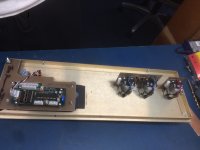
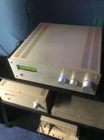
It's 2016 now, and it seems there's no recent build thread. I just started the Naim clone project. If interested, please join here and discuss for mods, experience etc.
I will post any information I've collected.
I started this new thread because I want to reorganize information which makes DIYer easier to read, and always kept updated.

My goals:
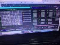
1. Optimize its performance while keep it sound as good as originals
2. Use modern part, tech, knowledge
3. Either Major/minor modifications are OK

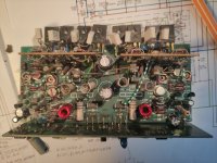
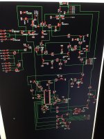
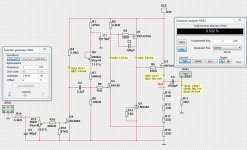
The original schematic
NAP250 schematic.jpg

Neil Mcbride's
sch2.gif

A MosFet Mod
NaimMosfet.jpg

LTSpice file, for your convenience:

View attachment NAP 140Bjt.zip

Multisim MS13 file:
View attachment NAIMp.zip

Some useful links
Modifying Naim Audio power amplifiers
Neil McBride's HiFi Stuff


2016/8/11 Adapted from Ian/rensli's post and others.
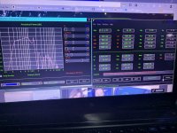
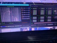
Inadequate filtering on the output:
They need an output coil. A 0R22 resistor just doesn't do it.

Still interference:
This doesn't stop all interference and one of the worst problems is long speaker speaker leads with the wrong reactance (L and C). The right type of cable, and it's not some exotic overpriced cable - snake oil issue, is detailed many times on the Naim audio site and forum plus the UK forums like PFM that recycle the topic ad infinitum.

For interest, I largely solved the problem with passing the leads 6 times through 32 dia. toroidal ferrite cores 0f 2-10 MHz range and changing the cable to a cheap, close spaced one, moving the amplifier to an elevated shelf between the speakers and removing the excess cable to about 2.5m lengths.
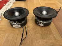
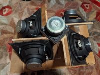
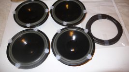
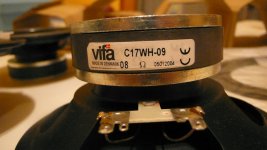
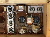

Drivers:

TIP41/42 drivers seem unlikely with their stone age performance but somehow, they work with little difference to MJE243/253 at typical domestic sound levels.

TIP41C/42C as drivers is good choice.. make sure they are not new chinese "fairchild" type.
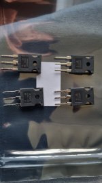
Output transistors
have varied from 2SC5200/A1943 to the suspect MT200 Sankens now supplied but here I used my own supply of 2SC5200/A1943(O)
2SC5200 with higher gain drivers will lead to bad sound and oscillations.

Input transistors
I could go through all the substitutes for the small transistors but you may note that is essential to fit the right MPSA06/56 limiter types to get correct action
Input stage types don't seem to be too fussy but if you think there should be a benefit in using matched pairs, guess again.
input stage
Intentionally thrown way out of balance to ensure that even order harmonics are not cancelled as the LTP is normally inclined to. This is largely what permits a desirable SQ .

VAS transistors
These should always be the original ZTX 653/753 from Diodes Inc.
Why? because they have high Cob (30pF) and speed, an unusual combination in a tiny 2W package. Being expensive at ~$1 ea, they were among the first parts to be ditched from the clone kits when the competition heated up a couple of years ago but rest assured that the low Cob types like 2SD667/B647 (12-20pF)and BC639/40 (On-Semi 6-9pF!) (variable according to manufacturer) begin to sound awful.


Caps
Polystyrene fails when old due to foil to wire corrosion . Philips used lead foils to overcome this , now banned .
COG ceramic are very good.
Don't use non-GOG( NPO ) ceramics!
Mylar are OK .
MKT caps in particular are usually the worst type to use.
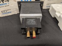
Transformer/Power
Dual 27~28Vac -> 35~40VDC
160VA or 300VA should be plenty and are common sizes for use with each or both channels respectively.

rensli:
Using regulated/double filtered psu for the front end will kill the sound for sure.
330R + 220uF filters in both supply's to the front-end is a way better idea - it will dampen down dynamics...on the good side.. you could turn the volume knob all the way up without compression. In overall, there you have to decide... do you want to listen to music or the background from the same music. If you pick last one, then go ahead and regulate/separate front-end... at the end it will be then hard to get good loud sound out of that amp ... you will be surprised how well it play's @ 20-30% volume, any higher level will be hell of a mess.


Tantalum caps on Naims

Electrolytics @ feedback and bypass is OK, but not as good as with PROPER TANT's.
The sound has changed but not necessarily been improved by substituting electrolytic caps.

2016/8/27 comments by Chris "anatech"
Which by definition, don't fit.
A couple rules of thumb for anyone working on any product. If the component doesn't fit where the old one did, don't use it. Secondly, never extend the leads to a component to mount it elsewhere! There are numerous reasons why you shouldn't do this, take your pick.

If you just want the best sound possible, go with polypropylene, but lead them off-board to the input sockets and well away from power leads. Use decent standard electrolytics like Panasonic or Rubycon etc. elsewhere.


******
Forum member Ruwe:
- Input transistors: ZTX692 - huge gain => very low base current => very low input distortion due to source equipment impedance and so on.
- VAS, current sources: XTX753/ZTX653
- Drivers: MJE243/253
- Output transistors: MJ3281 - best possible compromise current/price/bandwidth

- power resistors :
metal element, not wire wound. You can try that one (say 0.12-0.15 ohms) instead of a coil/resistor output combination. It works and sounds similar.

- capacitors :
styroflex (polystyrene) wherever possible, bipolar electrolytics of good quality for input and feedback. I use Mundorf. Or use tantalum, but watch for polarity.
- don't underestimate the power supply bank capacitors. Some high current computer grade work. Currently, I use Mallory 2x10000uF.
The rest is proper grounding, which means, no loops, no redundant grounds, no thin wires.


Join and have fun!

Attachments

  • schmod.gif
    schmod.gif
    49.6 KB · Views: 1,847
  • fft.gif
    fft.gif
    20.6 KB · Views: 1,844

NAP250 Global Feedback Addition

Just blew a NAP250 clone while attempting to add something similar to global feedback, except this is for a guitar amp. The intent was to reproduce the tube rectifier "droop" as the output current increases, which is pleasing to some ears, and also introduces some compression. A schematic is not available for this "improved" clone, but I know it is different for the following reasons. 1. The electrolytic capacitor off the 1k resistor connected to the TR2 base has its positive terminal connected to ground, and 2. There are a number of low value SMD capacitors presumably to prevent oscillation that do not appear on the attached schematic. Surely, there are other modifications as well.

Looking at some solid state power amps with "droop" feedback, it appears the usual way to do this is to ground the speaker's negative terminal through a sub-ohmic resistor, while running a wire from the speaker's negative terminal to the junction of the said capacitor and resistor (where the + sign is). Probably the one major mistake I made is the models I saw were complimentary designs, and not quasi-complimentary like the NAP250, and the capacitor in question was connected with the polarity as is usual--negative to ground.

Would anyone have an idea as the best way to do this, without blowing the second amp? Any comment cast will be appreciated.

Naim NAP250 Schem.jpg

2-way Synergy horn

There's been a lot of fun discussions on these forums, but it was time for me to make some speakers that:

  • Housed some of the speakers I have
  • Were a complete, enclosed system

What I've created I can't take credit for - it's thanks to the experience, genius and willingness to share on these forums that this pair of speakers came about:

  • xrk971 - for the Trynergy design, and the microTrynergy
  • bwaslo - for the absolutely amazing spreadsheet he's created that detail the panels for the CoSyne speaker design
  • weltersys - for the SynTripP design
  • HenrikEnquist - for the design of CamillaDSP
  • David McBean - for the invaluable HornResp tool
  • Tom Danley and Danley Sound Labs for their amazing designs and help throughout the community over the years

So what I've ended up here is a 2-way system, with each speaker using 4 of the Parts-Express 6.5" Polycone woofers, and one FaitalPRO 3FE22 at the apex of the horn. I've chosen a 500Hz crossover between them, and I have initially opted to add a 0.4 millisecond delay on the FaitalPRO driver for coherence.

The horn size I chose was mostly dependent on having panels large enough to mount the woofers, so I went with a 425Hz pattern control frequency at 90 degree horizontal, by 60 degree vertical coverage angles.

This project was by far one of the most complicated I've personally undertaken - lots of mitering, and making sure I had right-angle jigs set up for gluing the panels together. Given that I'd taken the 'pinwheel' approach for mounting the woofers (thanks Art), I couldn't follow the CoSyne spreadsheet to the letter.

Apart from the jigs, I made good use of duct tape. It's an amazing clamp when nothing else makes sense! 🙂

I also used Gorilla glue. The foaming nature of the glue filled some gaps created by my inaccuracies, and usually cured within a couple of hours, meaning that I could repeatedly go back to work on the horns in a single day.

The enclosures were based on the ideas from xrk971's rear chambers for the Trynergy - 11 litres per pair of drivers if I remember correctly. So, using the measurements from the spreadsheet I put the dimensions into HornResp, which calculated the volume of the horn, and so I aimed to add 22 litres to that, within practical means. I think the difference was more like 25 litres in the end, so not too bad.

I stuffed the back of the box with some food packaging - it looks like fibreglass, but it's made from recycled boxes (my wife receives it as packaging from a vegetable delivery service), so it was easy to handle, easy to staple in, and did a good job of deadening the walls of the box.

The wood was free. I found some pieces of 1/2" plywood, 1/2" chipboard from what looked like the back of a cheap cabinet (the staples were still in there), and some 1" siding! None of it was straight, so I made everything straight as best as I could while clamping and gluing.

Foam core board also makes an appearance in this design, as I needed to create gaskets to separate the drivers from the wood panels. It worked perfectly.

For the wiring, I used a good 16AWG speaker wire, and crimped on spade connectors, in case I ever needed to swap anything out, though this is probably just overkill. I have those 4-gang spring clamps that you see on the back of the lower-end amplifiers to use for bi-amping.

I've been impressed with the Synergy designs that I've built in the past, but this experience was completely different! A completed enclosure, in a stereo pair - wow!

"Wow" is an understatement, so I'll try to explain what that really means 🙂

  • These speakers are pretty much full range. There's no need for a sub unless you're trying to cover lower than, say 70Hz (not measured, just guessing) really well
  • The point source effect is astounding. Like Danley Sound Labs have mentioned in their YouTube videos, the speakers just disappear - it makes you wonder why the box is so big, because all of the sound's coming from the dead centre of the horn! I have them set up at different heights at the moment, and it's easy to tell that one is higher than the other!
  • Because of this, the stereo imaging is absolutely wonderful
  • These speakers are the closest thing to headphones that I've heard

I'm going to be setting them up with subs soon, and I may play with something like REW and FIR filtering to get them to match the space. From what I'm hearing, it's not going to take much to make them sound even better 🙂

Thanks for reading! I will be working on another pair soon, but they will be of a slightly different design, with the intent to be done more precisely. The boxes for this pair were rough, but I was really attempting to focus on making the horns as precise as I could!

Attachments

  • 1-jig.jpg
    1-jig.jpg
    52.4 KB · Views: 740
  • 2-gaskets.jpg
    2-gaskets.jpg
    55.9 KB · Views: 755
  • 3-test_fit.jpg
    3-test_fit.jpg
    51.2 KB · Views: 785
  • 4-almost_finished.jpg
    4-almost_finished.jpg
    41 KB · Views: 800

RTR DR-1 (circular electrostatic panel)

RTR DR-1 omni-directional loudspeakers.

I've tried in vain to find out more about these speakers on the internet. I found one reference where they claimed they sound better than the original Quad electrostatics.

In all curiosity I really want to know more about the circular electrostatic panel used.

Here is a single reference to a pair for sale on ebay but no mention about the circular electrostatic panel or what it looks like.

DR-1 for sale on ebay

FE206En in the fe208 recommended enclosure

Good afternoon,

planning to build FE208 recommended enclosure with some fe206 drivers.

As any decent Marina ply is really hard to come by in my area, I managed to buy some 2440x1220 18mm Birch Marine Ply locally.

I have had some fe206en's in storage for some time now, and I need to get some enclosures to get them out and active again.

Because of the so many cuts needed to make the fe208Sigma recommended enclosure, I have passed the wood onto a a client of mine in the cabinetry business who is going to cut the wood for me, because I have done a few previous smaller builds, so I know I am not that good at straight cuts 🙂

Back of my mind it is also to get some supertweeters, but I'll be happy to listen with the standard build first,then possibly look at the FT17H tweeters.

I have a range of amps 70's - 90's all solid state so will be interesting to see which one will sound the best with these drivers.
Or I may need to delve into the Valve/Tube world as feedback based on the sensitivity of the fe206's is that Valve/Tube amps are the go.

With a bit of luck, I'll have them built and running over the Christmas period, so looking forward to listening to these drivers.

Troubleshoot Soundcraftsmen A2502 power amp

Hi all, new member here after some advice please!

I have a Sound craftsmen A2502 stereo power amp, 250W. It's an American made solid state amp made around 1981.
The main capacitors x2 were replaced by a pro a year ago but since then it just stopped outputting any audio from both channels. If I turn the volume up I get buzzing from each channel.

So far I have:

Checked fuses OK, the dc voltage is correct both negative and minus. Checked for good continuity from both inputs past the volume controls to first device.

Unsure where to next check? What is confusing me is that both channels exhibit same issue.
Can someone please give me some pointers on where I should be looking to test next based on the attached schematic?

I have a good quality multimeter and a Fluke 123 scope meter for test equipment.
Note I'm new to electronics repair however am an electrician and industrial automation engineer so safety wise I'm happy with working on it, just it's not my usual cup of tea.

Thanks in advance!

Attachments

SB Acoustics Satori TW29RN-B Tweeter 4 ohm Pair For Sale

Full working order. supplied by Jantzen Audio,

Purchased 12/2020 from Jantzan Audio for a high end diy speaker (Fusion) project. 11 months use.
Crimp connections used for connections (no soldering)
Very good condition.
£195 plus postage within the UK

Attachments

  • PA310877.JPG
    PA310877.JPG
    301.2 KB · Views: 67
  • PA310878.JPG
    PA310878.JPG
    260.9 KB · Views: 66
  • PA310881.JPG
    PA310881.JPG
    380.7 KB · Views: 73
  • PA310885.JPG
    PA310885.JPG
    347.9 KB · Views: 66
  • PA310886.JPG
    PA310886.JPG
    361.8 KB · Views: 73
  • Like
Reactions: Pmus

  • Locked
Measured vs Specified power ratings of Pass X600.5

I have a pair of Pass Labs X600.5 monaural amplifiers with the following specs according to this webpage: https://www.passlabs.com/legacy_products/x600-5
Specified ratings Pass X600.5.JPG
600 Watts at 8 Ohms with 1% Distortion
1200 Watts at 4 Ohms with 1% Distortion

A professional engineer made the following measured powerratings:
Pass X600.5 Power Ratings.JPG
499,3 Watts at 8 Ohms with 1% Distortion
725,9 Watts at 4 Ohms with 1% Distortion

He even signs for it:
Pass X600.5 Power Ratings - Diplom Ingenieur.JPG

This discrepancy in power output is significant especially at 4 Ohms where almost 500 Watts seems to be disappeared.
As far as I know the tech is a professional working for decades in the field of highendaudio repairs.
I'm in no way implying that there's been any wrong intention by any party concerned, relating to these figures.
It's only one specific pair of X600.5's I'm referring to and I can't generalize on that base.
Maybe you can shed some light on this.
PS I edited the original post so my question is a more open minded query than a suggestion that the specified values were wrong.

4x Vifa/Scanspeak C17WH-09 Living Voice version

For sale is a quad of used, custom Vifa C17 woofers from Living voice Avatar speakers and a set of foam gaskets -$350
Yes , I know they are outrageously expensive for what used to be a cheap vifa driver but if you want to buy them from Living voice it will set you back 500 GBP plus expenses . I can offer help if somebody would like to make a speaker similar to LV Avatar but it's probably better and cheaper to make Troels version with Morel wave guided tweeter.

Attachments

  • 09182016 029.jpg
    09182016 029.jpg
    637.7 KB · Views: 381
  • 09182016 033.jpg
    09182016 033.jpg
    546 KB · Views: 406

Selmer Zodiac Twin 30 - seeking pics for clone build

I'm working on a clone of the Selmer Zodiac Twin 30, with some minor mods/improvements. Got a good schematic to work from, but I'm looking for someone who actually owns the amp to send me some pictures of the wiring layout. I've heard this amp is quite quiet and low microphonics for one with a pentode gain stage early in the preamp, and a lot of the reason for that is the layout and lead dress etc. I'm familiar with the physical separation of the preamp and power amp, to opposite sides of the chassy (genius!), but I'd like to replicate as much of the rest of the fine craftsmanship as possible.

Anyone own this amp or know someone who does? If anyone has a similar Selmer amp from that era, such as the Thunderbird or a twin 50, I'd love to see pics of those as well - even though the circuits are pretty different, I'd imagine I could learn a lot.

Amend EL34 circuit for KT88

Assistance or advice needed please! I intend to build a PP KT88 amplifier. I have the transformers, chassis and valves from a previous KT88 PP amp. My question is would this circuit with a little modification be suitable for KT88 valves? The reason being that I bought a PC board from Ebay that uses this circuit. I have some experience with valve builds but my knowledge of theory is limited, although I'm learning a lot from this site. Please ask questions if I haven't given sufficent information or the answers are elementary. I'm not proud🙂.

Attachments

PR-800 ClassA/AB Amplifier Kit

Hi,

Ready to embark on my next amplifier build and chose this one from eBay:

PR-800 Class A /AB Professional power amplifier board ?no heatatsink) CL135 | eBay

Would be good to hear from anyone who has built/bought previously and has any words of wisdom before I throw the power switch🙂. Or will I be out there my own again, path-finding another classic good amp design (Locanthi-T topology?) that has numerous opportunities for component/circuit tweaks that might turn it into a half-decent amplifier😉. I know one thing for sure, I wont be running it at 2.5A quiescent current per channel as I already have a perfectly good toaster in the kitchen😀

JBL LX300 crossover question

Hi All,

I have a pair of JBL LX300 standmount speakers that "I'm playing with".
This is the European version, 4ohm, 2 way speaker with around 3Khz crossover point.
Now I was looking at this crossover schematics and would like someone to explain the crossover parts role.
As you can see in the attached drawing the red marked section are for the HPF and LPF filtering, as far as I understand the Blue marked resistor is for Tweeter attenuation, but is the yellow marked section for? what it's purpose?

Thanks

Attachments

  • JBL LX300 crossover parts..jpg
    JBL LX300 crossover parts..jpg
    44.3 KB · Views: 154

All FET 3T Headphone Amp with H2 Generator

Nelson Pass has shown how to generate H2 Harmonics.
Can be described as a TUBE like sound.
This amplifier features a H2 generator.
It is U4 in the schematic.

The amplifier itself is an All FET 3 transistor device.
The distortion is quite high, because there is much H2 singing along.
As can be seen in the Fourier Analysis.

Attachments

  • All FET Amplifier with H2 Harmonic.jpg
    All FET Amplifier with H2 Harmonic.jpg
    344.2 KB · Views: 489
  • Fourier Analysis with H2 Harmonic.jpg
    Fourier Analysis with H2 Harmonic.jpg
    126 KB · Views: 469
  • Like
Reactions: daemon123

For Sale Elrog 300B amp with Monolith Magnetics Iron

Selling my amp project, due to moving on to different projects.

Would like to see first if there is some interest in the 'finished' amp, before splitting it up into parts.

The design is a 46 drives 300b setup, input is now directly to grid of 46 tube, so needs a preamp with some voltage gain. I used them in the past with Lundahl 7903 1:8 step-up transformers on the inputs and this is ideal, but requires a low output impedance of the previous stage.

Powersupply is a common tv damper diode bridge rectified LCLC-supply(Monolith) for both channels, with an additional local LC (Lundahl) decoupling for every stage. PSU is connected with an umbilical to the amp stages.
Powersupply has different primary voltage taps (220-230-240) for finetuning, and many different secondary voltage taps to get voltages from 150 to 600 in 50v steps, so it is basically a universal psu for many types of amp projects.

The amp chassis are still leftover from when they were monoblocks, so they have some open holes in them. The cases could easily be shortened, but I haven't found the time to do it.

Components are:

2x Monolith Magnetics SX-9 OPT, Nano-X core, 3.3K
2x Monolith Magnetics ITX-9 Interstage Transformers, Nano-X core, 30ma gap
2x Elrog 300B tubes
2x 46 tubes (have some extra, including a pair of globe 46)
15x asc X386 capacitors
2x LL1685 choke / 100ma/ 17H
2x LL1667 choke / 30ma / 120H
4x Tentlabs DC tube filament supplies
All dale 25W resistors
4x KLEInnovations RCA socket perfect harmony
4x KLEInnovations Classic Harmony binding posts
4x Jakeband teflon tube sockets, UX4 and UX5
1x Monolith Magnetics Power transformer: 220-230-240 Primary / Secondary 1 0-50-200, 250ma / Secondary 2 0-300-400,250ma / Secondary 3 0-6.3V, 5A
1x Monolith Magnetics Filament power transformer: 230-240 Primary/ Secondary 2x 0-3,6 3A / 2x 0-6,3 2.4A
2x Monolith Magnetics Chokes: 10H 225ma
1x Lessloss AC filter
Silver in waxed cotton wiring for signal chassis
Copper wiring in psu

SOLD

Attachments

  • IMG_3061.jpeg
    IMG_3061.jpeg
    393.8 KB · Views: 222
  • IMG_3062.jpeg
    IMG_3062.jpeg
    357.2 KB · Views: 242
  • IMG_3063.jpeg
    IMG_3063.jpeg
    333 KB · Views: 187
  • IMG_3064.jpeg
    IMG_3064.jpeg
    358.8 KB · Views: 193
  • IMG_3066.jpeg
    IMG_3066.jpeg
    444.7 KB · Views: 215
  • IMG_3067.jpeg
    IMG_3067.jpeg
    413 KB · Views: 213
  • IMG_3068.jpeg
    IMG_3068.jpeg
    425.5 KB · Views: 239
  • Like
Reactions: mterbekke

Connecting another bridge rectifier to an existing V+/V- supply

I need another V+ from the new bridged rectifier to power another circuit.

it might best explained with a diagram.

- I currently have the V+/V- supply in the diagram.

- I need to tap into the transformer to power up another circuit (lower portion of the diagram with the bridge rectifier)

- The transformer that I'm using have 2 secondaries connected in series. The connected wires become my center-tap ground.

Is this possible? If yes, what changes do I need (if required) to make it work?

Thanks a lot.

PS. apologies for the quality of the diagram. It's a mashed up I made using MS Paint. 😀

-------------

Edit1: I thought just came to mind. Instead of tapping into the transformer, perhaps I can tap V+ from the first capacitor immediately after the existing rectifiers?

Edit2: the existing supply is a regulated +/- 12V. The new supply will give me more than +12V.

Edit3: The 2 grounds from both supplies are not connected.

6gEoe.png

ZONERIPPER MAX 1TB SSD. Streamer/server/cd ripper. Great condition.

Zoneripper max with new 1tb crucial Ssd.In great condition.Similar to Innuos Zenith.Can stream Tidal/Qobuz/Deezer/Spotify plus all internet radio. Can hold 2500 ripped cds.Bargain at £275 plus postage.Happy to demonstrate in Naim system if local.

Attachments

  • 648F4CAF-D474-4622-B455-4EB516347429.jpeg
    648F4CAF-D474-4622-B455-4EB516347429.jpeg
    441.6 KB · Views: 93
  • 6C4ADA4E-E147-4126-992B-F6AD54BA26BC.jpeg
    6C4ADA4E-E147-4126-992B-F6AD54BA26BC.jpeg
    392.3 KB · Views: 92
  • 0BCFE019-B2B4-470D-81D4-01D5CE90BB8B.jpeg
    0BCFE019-B2B4-470D-81D4-01D5CE90BB8B.jpeg
    368.9 KB · Views: 88
  • 77761FFE-93CD-4240-81D3-FDFE163E0E9E.png
    77761FFE-93CD-4240-81D3-FDFE163E0E9E.png
    466.8 KB · Views: 98
  • 20C00EB3-536A-4C7A-AB67-DB5BF2735B6B.jpeg
    20C00EB3-536A-4C7A-AB67-DB5BF2735B6B.jpeg
    378.6 KB · Views: 98

Foam Tline!

living in an RV leaves one with very little room and weight capacity, so I used home Depot rigid foam board to make a Tline that fits under the tv. Had really low expectations, but so far pleasantly surprised!

Going to experiment with a little stuffing before gluing the top on.

Just thought I would share for the fun of it!

Attachments

  • IMG_20221112_180539491_HDR.jpg
    IMG_20221112_180539491_HDR.jpg
    350.4 KB · Views: 109
  • Like
Reactions: geraldfryjr and GM

Field coil PSU

I'm building a high voltage tube PSU for a pair of full range field coil drivers.
I am connecting the drivers in parallel. Now my question is: which would be a better topology: LCLCLC, with the last capacitor doubled to each driver for decoupling or would it be better to do LC(RC)LC, with the last LC doubled to each driver. I only have room for 3 chokes in the case, hence the limitation of trying to accomplish it with 3...

Thanks

Magnepan LRS Tweeter attenuation?

I just picked up a pair of used Magnepan LRS.....Replaced Magnepan MMGs.....In a word, FANTASTIC! Huge improvement over the MMGs in bass, dynamics, midrange, vocals......But in my room, a bit bright. I have the recommended attenuation resistors...1 ohm and 2 ohm.....But my question, can I use an L-Pad instead of a standard resistor? would allow more adjustability.......The back of the LRS has a place to insert a resistor in series with the tweeter. How would I wire the tree terminals from an L-Pad...Thanks
Projects by fanatics, for fanatics
Get answers and advice for everyone wanting to learn the art of audio.
Join the Community
507,553
Members
7,876,630
Messages

Filter

Forum Statistics

Threads
405,710
Messages
7,876,630
Members
507,553
Latest member
mcraghead