Hi folks,
It's 2016 now, and it seems there's no recent build thread. I just started the Naim clone project. If interested, please join here and discuss for mods, experience etc.
I will post any information I've collected.
I started this new thread because I want to reorganize information which makes DIYer easier to read, and always kept updated.
My goals:
1. Optimize its performance while keep it sound as good as originals
2. Use modern part, tech, knowledge
3. Either Major/minor modifications are OK
The original schematic

Neil Mcbride's

A MosFet Mod

LTSpice file, for your convenience:
View attachment NAP 140Bjt.zip
Multisim MS13 file:
View attachment NAIMp.zip
Some useful links
Modifying Naim Audio power amplifiers
Neil McBride's HiFi Stuff
2016/8/11 Adapted from Ian/rensli's post and others.
Inadequate filtering on the output:
They need an output coil. A 0R22 resistor just doesn't do it.
Still interference:
This doesn't stop all interference and one of the worst problems is long speaker speaker leads with the wrong reactance (L and C). The right type of cable, and it's not some exotic overpriced cable - snake oil issue, is detailed many times on the Naim audio site and forum plus the UK forums like PFM that recycle the topic ad infinitum.
For interest, I largely solved the problem with passing the leads 6 times through 32 dia. toroidal ferrite cores 0f 2-10 MHz range and changing the cable to a cheap, close spaced one, moving the amplifier to an elevated shelf between the speakers and removing the excess cable to about 2.5m lengths.
Drivers:
TIP41/42 drivers seem unlikely with their stone age performance but somehow, they work with little difference to MJE243/253 at typical domestic sound levels.
TIP41C/42C as drivers is good choice.. make sure they are not new chinese "fairchild" type.
Output transistors
have varied from 2SC5200/A1943 to the suspect MT200 Sankens now supplied but here I used my own supply of 2SC5200/A1943(O)
2SC5200 with higher gain drivers will lead to bad sound and oscillations.
Input transistors
I could go through all the substitutes for the small transistors but you may note that is essential to fit the right MPSA06/56 limiter types to get correct action
Input stage types don't seem to be too fussy but if you think there should be a benefit in using matched pairs, guess again.
input stage
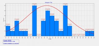
Intentionally thrown way out of balance to ensure that even order harmonics are not cancelled as the LTP is normally inclined to. This is largely what permits a desirable SQ .
VAS transistors
These should always be the original ZTX 653/753 from Diodes Inc.
Why? because they have high Cob (30pF) and speed, an unusual combination in a tiny 2W package. Being expensive at ~$1 ea, they were among the first parts to be ditched from the clone kits when the competition heated up a couple of years ago but rest assured that the low Cob types like 2SD667/B647 (12-20pF)and BC639/40 (On-Semi 6-9pF!) (variable according to manufacturer) begin to sound awful.
Caps
Polystyrene fails when old due to foil to wire corrosion . Philips used lead foils to overcome this , now banned .
COG ceramic are very good.
Don't use non-GOG( NPO ) ceramics!
Mylar are OK .
MKT caps in particular are usually the worst type to use.
Transformer/Power
Dual 27~28Vac -> 35~40VDC
160VA or 300VA should be plenty and are common sizes for use with each or both channels respectively.
rensli:
Using regulated/double filtered psu for the front end will kill the sound for sure.
330R + 220uF filters in both supply's to the front-end is a way better idea - it will dampen down dynamics...on the good side.. you could turn the volume knob all the way up without compression. In overall, there you have to decide... do you want to listen to music or the background from the same music. If you pick last one, then go ahead and regulate/separate front-end... at the end it will be then hard to get good loud sound out of that amp ... you will be surprised how well it play's @ 20-30% volume, any higher level will be hell of a mess.
Tantalum caps on Naims
Electrolytics @ feedback and bypass is OK, but not as good as with PROPER TANT's.
The sound has changed but not necessarily been improved by substituting electrolytic caps.
2016/8/27 comments by Chris "anatech"
Which by definition, don't fit.
A couple rules of thumb for anyone working on any product. If the component doesn't fit where the old one did, don't use it. Secondly, never extend the leads to a component to mount it elsewhere! There are numerous reasons why you shouldn't do this, take your pick.
If you just want the best sound possible, go with polypropylene, but lead them off-board to the input sockets and well away from power leads. Use decent standard electrolytics like Panasonic or Rubycon etc. elsewhere.
******
Forum member Ruwe:
- Input transistors: ZTX692 - huge gain => very low base current => very low input distortion due to source equipment impedance and so on.
- VAS, current sources: XTX753/ZTX653
- Drivers: MJE243/253
- Output transistors: MJ3281 - best possible compromise current/price/bandwidth
- power resistors :
metal element, not wire wound. You can try that one (say 0.12-0.15 ohms) instead of a coil/resistor output combination. It works and sounds similar.
- capacitors :
styroflex (polystyrene) wherever possible, bipolar electrolytics of good quality for input and feedback. I use Mundorf. Or use tantalum, but watch for polarity.
- don't underestimate the power supply bank capacitors. Some high current computer grade work. Currently, I use Mallory 2x10000uF.
The rest is proper grounding, which means, no loops, no redundant grounds, no thin wires.
Join and have fun!
It's 2016 now, and it seems there's no recent build thread. I just started the Naim clone project. If interested, please join here and discuss for mods, experience etc.
I will post any information I've collected.
I started this new thread because I want to reorganize information which makes DIYer easier to read, and always kept updated.
My goals:
1. Optimize its performance while keep it sound as good as originals
2. Use modern part, tech, knowledge
3. Either Major/minor modifications are OK
The original schematic
Neil Mcbride's
A MosFet Mod
LTSpice file, for your convenience:
View attachment NAP 140Bjt.zip
Multisim MS13 file:
View attachment NAIMp.zip
Some useful links
Modifying Naim Audio power amplifiers
Neil McBride's HiFi Stuff
2016/8/11 Adapted from Ian/rensli's post and others.
Inadequate filtering on the output:
They need an output coil. A 0R22 resistor just doesn't do it.
Still interference:
This doesn't stop all interference and one of the worst problems is long speaker speaker leads with the wrong reactance (L and C). The right type of cable, and it's not some exotic overpriced cable - snake oil issue, is detailed many times on the Naim audio site and forum plus the UK forums like PFM that recycle the topic ad infinitum.
For interest, I largely solved the problem with passing the leads 6 times through 32 dia. toroidal ferrite cores 0f 2-10 MHz range and changing the cable to a cheap, close spaced one, moving the amplifier to an elevated shelf between the speakers and removing the excess cable to about 2.5m lengths.
Drivers:
TIP41/42 drivers seem unlikely with their stone age performance but somehow, they work with little difference to MJE243/253 at typical domestic sound levels.
TIP41C/42C as drivers is good choice.. make sure they are not new chinese "fairchild" type.
Output transistors
have varied from 2SC5200/A1943 to the suspect MT200 Sankens now supplied but here I used my own supply of 2SC5200/A1943(O)
2SC5200 with higher gain drivers will lead to bad sound and oscillations.
Input transistors
I could go through all the substitutes for the small transistors but you may note that is essential to fit the right MPSA06/56 limiter types to get correct action
Input stage types don't seem to be too fussy but if you think there should be a benefit in using matched pairs, guess again.
input stage
Intentionally thrown way out of balance to ensure that even order harmonics are not cancelled as the LTP is normally inclined to. This is largely what permits a desirable SQ .
VAS transistors
These should always be the original ZTX 653/753 from Diodes Inc.
Why? because they have high Cob (30pF) and speed, an unusual combination in a tiny 2W package. Being expensive at ~$1 ea, they were among the first parts to be ditched from the clone kits when the competition heated up a couple of years ago but rest assured that the low Cob types like 2SD667/B647 (12-20pF)and BC639/40 (On-Semi 6-9pF!) (variable according to manufacturer) begin to sound awful.
Caps
Polystyrene fails when old due to foil to wire corrosion . Philips used lead foils to overcome this , now banned .
COG ceramic are very good.
Don't use non-GOG( NPO ) ceramics!
Mylar are OK .
MKT caps in particular are usually the worst type to use.
Transformer/Power
Dual 27~28Vac -> 35~40VDC
160VA or 300VA should be plenty and are common sizes for use with each or both channels respectively.
rensli:
Using regulated/double filtered psu for the front end will kill the sound for sure.
330R + 220uF filters in both supply's to the front-end is a way better idea - it will dampen down dynamics...on the good side.. you could turn the volume knob all the way up without compression. In overall, there you have to decide... do you want to listen to music or the background from the same music. If you pick last one, then go ahead and regulate/separate front-end... at the end it will be then hard to get good loud sound out of that amp ... you will be surprised how well it play's @ 20-30% volume, any higher level will be hell of a mess.
Tantalum caps on Naims
Electrolytics @ feedback and bypass is OK, but not as good as with PROPER TANT's.
The sound has changed but not necessarily been improved by substituting electrolytic caps.
2016/8/27 comments by Chris "anatech"
Which by definition, don't fit.
A couple rules of thumb for anyone working on any product. If the component doesn't fit where the old one did, don't use it. Secondly, never extend the leads to a component to mount it elsewhere! There are numerous reasons why you shouldn't do this, take your pick.
If you just want the best sound possible, go with polypropylene, but lead them off-board to the input sockets and well away from power leads. Use decent standard electrolytics like Panasonic or Rubycon etc. elsewhere.
******
Forum member Ruwe:
- Input transistors: ZTX692 - huge gain => very low base current => very low input distortion due to source equipment impedance and so on.
- VAS, current sources: XTX753/ZTX653
- Drivers: MJE243/253
- Output transistors: MJ3281 - best possible compromise current/price/bandwidth
- power resistors :
metal element, not wire wound. You can try that one (say 0.12-0.15 ohms) instead of a coil/resistor output combination. It works and sounds similar.
- capacitors :
styroflex (polystyrene) wherever possible, bipolar electrolytics of good quality for input and feedback. I use Mundorf. Or use tantalum, but watch for polarity.
- don't underestimate the power supply bank capacitors. Some high current computer grade work. Currently, I use Mallory 2x10000uF.
The rest is proper grounding, which means, no loops, no redundant grounds, no thin wires.
Join and have fun!
Attachments
Last edited:
You might know that the 1st design you posted is actually for a single board from the NAP250. The NAP140 uses lower rail voltages (+/-34) and slightly different emitter resistors in the front end to set bias. These details and the transistor types used are important if you are serious about what you are comparing and cloning, also the value of any simulations and the final sound quality.
In reality, the sound quality of most generic kit NAP clones and variations isn't good at all. Many of the original circuit design features that perform poorly by today's standards, were actually necessary because the harmonic distortion produced was finely tuned in the original and so, it can still sound very impressive in audiophile terms if the design is adhered to. This was backed up by experience with newer Caowei NAP200 clone kit builds.
I think that to make cloning this design worthwhile, you need to preserve the many original features, including the components which clearly affect the distortion, such as the critical VAS transistors. These are discussed again and again in the thread referenced, as each newbie rediscovered their importance.
As it seems you are more interested in circuit variations and experiment, the big Ebay kit thread here, started in 2007, actually covered many variations including a proposed mosfet output stage: http://www.diyaudio.com/forums/solid-state/112453-nap-140-clone-amp-kit-ebay.html You may be interested to find that isolating the front end with cap multipliers was not found successful in terms of SQ. Check Rensli's comments on his experiments.
Ian:
Thank you so much for your advises. I will take them as notes.
🙂
Eric
Thank you so much for your advises. I will take them as notes.
🙂
Eric
You might know that the 1st design you posted is actually for a single board from the NAP250. The NAP140 uses lower rail voltages (+/-34) and slightly different emitter resistors in the front end to set bias. These details and the transistor types used are important if you are serious about what you are comparing and cloning, also the value of any simulations and the final sound quality.
In reality, the sound quality of most generic kit NAP clones and variations isn't good at all. Many of the original circuit design features that perform poorly by today's standards, were actually necessary because the harmonic distortion produced was finely tuned in the original and so, it can still sound very impressive in audiophile terms if the design is adhered to. This was backed up by experience with newer Caowei NAP200 clone kit builds.
I think that to make cloning this design worthwhile, you need to preserve the many original features, including the components which clearly affect the distortion, such as the critical VAS transistors. These are discussed again and again in the thread referenced, as each newbie rediscovered their importance.
As it seems you are more interested in circuit variations and experiment, the big Ebay kit thread here, started in 2007, actually covered many variations including a proposed mosfet output stage: http://www.diyaudio.com/forums/solid-state/112453-nap-140-clone-amp-kit-ebay.html You may be interested to find that isolating the front end with cap multipliers was not found successful in terms of SQ. Check Rensli's comments on his experiments.
Hi,
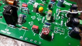
So it begins.
After read several hundred pages that Ian recommended, here is my result so far.
A BF862 buffer was added. Some FET cascoded to have better rejection
Many thanks to Ian.
Still some questions:
1. Will polystyrene inevitable on this design? MKP/MKT will make diff SQ?
2. Is SMD 68uF AVX OK for this design? It's hard for me to get a TH 68uF
Any comment or help is highly appreciated.
Attachments
You are to be congratulated on reading that thread. It wanders off-topic and ends up in many dead ends but there are lots of leads to follow if you are interested to research them.
The polystyrene caps are advisable but if you can't source them, silvered mica or multilayer COG ceramic caps are fair substitutes, though many builders report significant differences with changing cap types such as Cdom. (the Miller compensation cap for the voltage amplifier). My experience with MKP and MKT film types for HF filters and compensation is not always good. MKT caps in particular are of variable quality but usually the worst type to use. However, all film types seem to perform better at higher audio frequencies when higher voltage rated parts such as 250 - 400V are used, which I assume is associated with the polymer film thickness and hence its dielectric properties. Better film types again would be film/foil construction, such as FKP type but these may be too large, which can introduce other problems. I'm not sure about SMD caps in Naim gear, perhaps others have a view.
In looking at your schematic, I notice you have specified extremely close tolerance mil. spec. resistors and you are cascoding the front end transtors everywhere for reasons I suspect won't bring any worthwhile benefits. High precision resistors have little to offer audio, other than a high cost so when I see these parts specified, I get the feeling that the designer is using overkill quality because they can, rather than for any technical reason.
Still, it's your design and thanks for sharing your interesting additions. I'm sure people here would like to hear more about them and why you chose to do this.
Ian,
I use FET cascoding because I got this idea after reading Jung's CCS paper. Also, in my simulation, it does makes a better result, technically. Not sure about it's impact on SQ, but these FETs can be bypassed and become just original design---Good for A-B testing, isn't it?🙂
Regards,
Eric
I use FET cascoding because I got this idea after reading Jung's CCS paper. Also, in my simulation, it does makes a better result, technically. Not sure about it's impact on SQ, but these FETs can be bypassed and become just original design---Good for A-B testing, isn't it?🙂
Regards,
Eric
You are to be congratulated on reading that thread. It wanders off-topic and ends up in many dead ends but there are lots of leads to follow if you are interested to research them.
The polystyrene caps are advisable but if you can't source them, silvered mica or multilayer COG ceramic caps are fair substitutes, though many builders report significant differences with changing cap types such as Cdom. (the Miller compensation cap for the voltage amplifier). My experience with MKP and MKT film types for HF filters and compensation is not always good. MKT caps in particular are of variable quality but usually the worst type to use. However, all film types seem to perform better at higher audio frequencies when higher voltage rated parts such as 250 - 400V are used, which I assume is associated with the polymer film thickness and hence its dielectric properties. Better film types again would be film/foil construction, such as FKP type but these may be too large, which can introduce other problems. I'm not sure about SMD caps in Naim gear, perhaps others have a view.
In looking at your schematic, I notice you have specified extremely close tolerance mil. spec. resistors and you are cascoding the front end transtors everywhere for reasons I suspect won't bring any worthwhile benefits. High precision resistors have little to offer audio, other than a high cost so when I see these parts specified, I get the feeling that the designer is using overkill quality because they can, rather than for any technical reason.
Still, it's your design and thanks for sharing your interesting additions. I'm sure people here would like to hear more about them and why you chose to do this.
![IMG20160818201843[1].jpg](/community/data/attachments/525/525400-864433cc765ef251559b9686e2493198.jpg?hash=hkQzzHZe8l)
Hi,
I had metallic sound from one of the AVX 10uF LOW ESR(120mR) TANT SMD.
It costed me ~1.5€ each. Exact code: TCJD106M050R0120. It is a nightmare.
Softest sound, no difference between 10uF WIMA MKT are TAP106K050CCS 10uF capacitors from AVX, they are the same price and they perform very good on the input.
I suspect all AVX THT's that have "CCS" endings are good and soft.
ATM, i took a huge pause from tuning naim's or they'r clones sound.
My suggestion to you would be to make BIG size PCB, to make sure output stage is well far apart from input and VAS so that nothing couples in or out trought the circuit . Don't add GND planes. Little noise is not a probem imo, its the audio we are listening.
Do not go for traditional 1 transformer 1 center-tap winding. If possible, go dual mono and separate box for each. This will instantly leave you less problem's to fight/think/wonder about. My experience shows that regulated PSU feeding 1 channel only is good, without peaks, clean, nice tight, very very bright sound!!!!
Second, make box that way so you could easily access soldering points and do mods with in seconds from power off and on.
Electrolytics @ feedback and bypass is OK, but not as good as with PROPER TANT's.
Using regulated/double filtered psu for the front end will kill the sound for sure.
330R + 220uF filters in both supply's to the front-end is a way better idea - it will dampen down dynamics...on the good side.. you could turn the volume knob all the way up without compression. In overall, there you have to decide... do you want to listen to music or the background from the same music. If you pick last one, then go ahead and regulate/separate front-end... at the end it will be then hard to get good loud sound out of that amp ... you will be surprised how well it play's @ 20-30% volume, any higher level will be hell of a mess.
2SC5200 with higher gain drivers will lead to bad sound and oscillations.
TIP41C/42C as drivers is good choice.. make sure they are not new chinese "fairchild" type.
I have heard this amp playing good, so i will be on it soon again with new PCB layout. 2N3055 as outputs.
Don't use SMT part's on naim amplifier.Is SMD 68uF AVX OK for this design
I had metallic sound from one of the AVX 10uF LOW ESR(120mR) TANT SMD.
It costed me ~1.5€ each. Exact code: TCJD106M050R0120. It is a nightmare.
Softest sound, no difference between 10uF WIMA MKT are TAP106K050CCS 10uF capacitors from AVX, they are the same price and they perform very good on the input.
I suspect all AVX THT's that have "CCS" endings are good and soft.
ATM, i took a huge pause from tuning naim's or they'r clones sound.
My suggestion to you would be to make BIG size PCB, to make sure output stage is well far apart from input and VAS so that nothing couples in or out trought the circuit . Don't add GND planes. Little noise is not a probem imo, its the audio we are listening.
Do not go for traditional 1 transformer 1 center-tap winding. If possible, go dual mono and separate box for each. This will instantly leave you less problem's to fight/think/wonder about. My experience shows that regulated PSU feeding 1 channel only is good, without peaks, clean, nice tight, very very bright sound!!!!
Second, make box that way so you could easily access soldering points and do mods with in seconds from power off and on.
Electrolytics @ feedback and bypass is OK, but not as good as with PROPER TANT's.
Using regulated/double filtered psu for the front end will kill the sound for sure.
330R + 220uF filters in both supply's to the front-end is a way better idea - it will dampen down dynamics...on the good side.. you could turn the volume knob all the way up without compression. In overall, there you have to decide... do you want to listen to music or the background from the same music. If you pick last one, then go ahead and regulate/separate front-end... at the end it will be then hard to get good loud sound out of that amp ... you will be surprised how well it play's @ 20-30% volume, any higher level will be hell of a mess.
2SC5200 with higher gain drivers will lead to bad sound and oscillations.
TIP41C/42C as drivers is good choice.. make sure they are not new chinese "fairchild" type.
I have heard this amp playing good, so i will be on it soon again with new PCB layout. 2N3055 as outputs.
Last edited:
tl;dr:
If you want what older Naim does sonically, you clone it closely (and you won't get that, or even stability, from chicom kits). There are some specific, and simple inclusions that are the first things derided but are intrinsically part of the 'Classic/Olive' Naim gestalt: the specifically-imbalanced LTP to tailor the output harmonic series, the interaction with the specified speaker cable impedance/characteristic; other lesser items: it is a system, not a thing in isolation.
If you want a high(er)-performing Lin-based topology based on some objective metric, there are many other places to look. Start there.
Playing somewhere in the middle is neither use nor ornament, for several reasons, but the simplification is - you've neither improved one nor made the other sound more 'sympathetic' /'musical' (or whatever you want to call it this week)
MC -acoustica.org.uk
[and no - I don't actually own or use Naim or Naim-alike amps! I do keep an Nait2 as a sense-check though 😉 ]
Last edited:
Agreed, unfortunately. You won't get anywhere by modifying key design areas with technical refinements. You will almost certainly lose the characteristic sound colouration that made the early Naim models so impressive to enthusiasts >20 years ago.......If you want a high(er)-performing Lin-based topology based on some objective metric, there are many other places to look. Start there.
That alone is enough to suggest analysing the signature Naim distortion harmonics and starting work afresh with a 'textbook' amplifier model design rather than the already "tweaked" commercial audio product. You will need need an original example for that as the cheap clone kits sound nothing like Naim products/audio systems.
Last edited:
Hi,
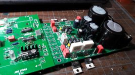
Thanks for all advises. Here're some updates:
1.I planed to use Sigma 22 as regulator. Dual 36VAC In (From my NAD326BEE), +-48VDC and regulated to +-40VDC (According to the author, 8V-9V drop should be maintained.)
2. I love what ROE 2.2 uF sounds like, so it's applied as input cap.
3. Unfortunately, there's a power short when I was measuring on Sigma 22, it failed to supply +-40 VDC anymore. So I am making effort on power issues.
Attachments
Hi Eric,
NP0 = Negative Positive (temperature coefficient) zero. = safe to use.
I feel similarly to the Naim products as others have commented. The best thing for a Nait is 1/2 hour at 450 degrees on a cookie sheet. It has more design flaws than normally seen in an actual product.
As has been pointed out earlier, either build an exact copy of it, or something else entirely. Not unless you do like the sound of something in between that and anything else.
A couple rules of thumb for anyone working on any product. If the component doesn't fit where the old one did, don't use it. Secondly, never extend the leads to a component to mount it elsewhere! There are numerous reasons why you shouldn't do this, take your pick.
Finally, Eric, I applaud you for being able to wade through all that stuff in those threads!
Best, Chris
C0G/NP0 are both the temperature stable ceramic capacitor type (same type)COG ceramic are very good.
Don't use non-GOG( NPO ) ceramics!
NP0 = Negative Positive (temperature coefficient) zero. = safe to use.
I feel similarly to the Naim products as others have commented. The best thing for a Nait is 1/2 hour at 450 degrees on a cookie sheet. It has more design flaws than normally seen in an actual product.
As has been pointed out earlier, either build an exact copy of it, or something else entirely. Not unless you do like the sound of something in between that and anything else.
Which by definition, don't fit.I fitted huge polypropylene caps
A couple rules of thumb for anyone working on any product. If the component doesn't fit where the old one did, don't use it. Secondly, never extend the leads to a component to mount it elsewhere! There are numerous reasons why you shouldn't do this, take your pick.
Finally, Eric, I applaud you for being able to wade through all that stuff in those threads!
Best, Chris
Hi Eric,
C0G/NP0 are both the temperature stable ceramic capacitor type (same type)
NP0 = Negative Positive (temperature coefficient) zero. = safe to use.
I feel similarly to the Naim products as others have commented. The best thing for a Nait is 1/2 hour at 450 degrees on a cookie sheet. It has more design flaws than normally seen in an actual product.
As has been pointed out earlier, either build an exact copy of it, or something else entirely. Not unless you do like the sound of something in between that and anything else.
Which by definition, don't fit.
A couple rules of thumb for anyone working on any product. If the component doesn't fit where the old one did, don't use it. Secondly, never extend the leads to a component to mount it elsewhere! There are numerous reasons why you shouldn't do this, take your pick.
Finally, Eric, I applaud you for being able to wade through all that stuff in those threads!
Best, Chris
Hi Chris,
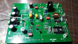
Thank you for your comments. I agree that "either build an exact copy of it, or something else entirely."
After some reflection, I decided to bypass the buffer part(BF862) , and after that, the design is entirely the original Naim🙂
About PSU, I think Simga 22 is worth trying. I think I will go for 2 different ways:
1. Sigma 22
2. Original regulator
Though S22 is not original design, why not just consider it as an experiment, and make some fun😉 I mean, I still agree "All-or-non copy", but it's worth trying.
And yes, I have read all pages of that thread, which is exhausting but worthy. I started this new thread because I want to reorganize information which makes DIYer easier to read, and always kept updated.
Best,
Eric
Hi,
Don't use SMT part's on naim amplifier.
I had metallic sound from one of the AVX 10uF LOW ESR(120mR) TANT SMD.
It costed me ~1.5€ each. Exact code: TCJD106M050R0120. It is a nightmare.
Softest sound, no difference between 10uF WIMA MKT are TAP106K050CCS 10uF capacitors from AVX, they are the same price and they perform very good on the input.
I suspect all AVX THT's that have "CCS" endings are good and soft.
ATM, i took a huge pause from tuning naim's or they'r clones sound.
My suggestion to you would be to make BIG size PCB, to make sure output stage is well far apart from input and VAS so that nothing couples in or out trought the circuit . Don't add GND planes. Little noise is not a probem imo, its the audio we are listening.
Do not go for traditional 1 transformer 1 center-tap winding. If possible, go dual mono and separate box for each. This will instantly leave you less problem's to fight/think/wonder about. My experience shows that regulated PSU feeding 1 channel only is good, without peaks, clean, nice tight, very very bright sound!!!!
Second, make box that way so you could easily access soldering points and do mods with in seconds from power off and on.
Electrolytics @ feedback and bypass is OK, but not as good as with PROPER TANT's.
Using regulated/double filtered psu for the front end will kill the sound for sure.
330R + 220uF filters in both supply's to the front-end is a way better idea - it will dampen down dynamics...on the good side.. you could turn the volume knob all the way up without compression. In overall, there you have to decide... do you want to listen to music or the background from the same music. If you pick last one, then go ahead and regulate/separate front-end... at the end it will be then hard to get good loud sound out of that amp ... you will be surprised how well it play's @ 20-30% volume, any higher level will be hell of a mess.
2SC5200 with higher gain drivers will lead to bad sound and oscillations.
TIP41C/42C as drivers is good choice.. make sure they are not new chinese "fairchild" type.
I have heard this amp playing good, so i will be on it soon again with new PCB layout. 2N3055 as outputs.
Hi rensli,
Thank you for your suggestions, very good information that will help.
I will update the article by adding your comment if you don't mind?
Best,
Eric
no, i do not mind. Just please don't waste your time doing experiments that allready has been tried.
Was it Ian Finch or Nigeal person who mentioned that most of the ppl are reverting back to the original design after mod's, be it H-140( with 330R/220uF filters) or NAP140/250 design.
Feedback 1.8k/39pF combo is missing, 1st post.
Was it Ian Finch or Nigeal person who mentioned that most of the ppl are reverting back to the original design after mod's, be it H-140( with 330R/220uF filters) or NAP140/250 design.
the design is entirely the original Naim
Feedback 1.8k/39pF combo is missing, 1st post.
Last edited:
Feedback 1.8k/39pF combo is missing, 1st post.
Yes, I deleted that in the post, but I can't remove it from attachment.
(what dose "ppl" stands for? )
Let me make for sure:
1. Don't go for regulated PSU (even original NAP250 reg?)
2. 330R + 220uF filters for the front end from simple CRC filter😕
"ppl" may be intended to read people.
This is an english language Forum.
Anybody that posts in another language is required by the Forum decrees, to post an accompanying translation.
This is an english language Forum.
Anybody that posts in another language is required by the Forum decrees, to post an accompanying translation.
Nice work to compile all the info here! Good Job!
Btw, where you guys are purchasing the naim PCB boards?
Btw, where you guys are purchasing the naim PCB boards?
Nice to have this little summary of the NAP cloning efforts through the years.
I have two notes:
I have two notes:
- In the last 10 or so years I find C0G/N0P ceramics excellent substitutes for the polystyrene or mica type caps
- In my recent designs I use mostly SMT parts and I don't understand why anyone would use anything else in 21st century. They save space, have much less parasitics, and offer so much choice... Resistors, capacitors, transistors, diodes, inductors, I prefer all of them in SMT up to 1 watt of power, generally speaking. Above that - it depends...
- Home
- Amplifiers
- Solid State
- Naim Amp 2016 Build thread