Sony TC-WA8ESA / 1990s Dual Deck Rubber Ring Identification

Hello. I am hoping someone can help me identify a small rubber ring or gasket that I need to replace in my Sony TC-WA8ESA. However, I think this can be read as a general question for 1990s Sony dual decks. I was sold this deck and told that it simply needed its belts to be replaced. It actually came with replacement belts. Cleaning and replacing them was easy, but now I see that the real problem is that a ring or gasket that one of the belts ultimately rests on, which mediates how it moves the flywheel, has also disintegrated and is the real problem. The ring in question connects to the small pulley connected to Capstan Motor (M1) (Matsushita MMI-6H2LWK). I have attached pictures of the piece as well as where in the schematics I believe it is. If anyone can help me figure out if there is a replacement available I'd greatly appreciate it. It is my hope that it is a ring that Sony uses in other decks and is available somehow. Thank you.

Manual is located here: https://www.hifiengine.com/manual_library/sony/tc-wa8es.shtml

SONYPARTS3.jpg
SONYPARTS2.jpg
SONYPARTS1.jpg
SONYTHINGY1.jpg
SONYTHINGY3.jpg


It goes on the white ring in the middle of the image below. The belt is supposed on be placed on top of it.
PXL_20230304_183216028.MP.jpg


I'm hoping I am not SOL. A lot of these dual decks seem to need this piece and I am having difficulty finding information about it.

Musical Fidelity A300-Humming Power Supply

Hello,

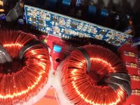
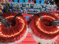
I recently repaired and recapped a Musical Fidelity A300. One of the output transistors was blown. After putting everything back together I now have a loud humming coming out of one of the toroidal transformers that I don't remember it having prior. I have very limited experience with power supply issues. Any ideas on where to start? Thank you in advance!

Sonos 5 (stereo pair) positioning

Hi everyone been a while,

Have just got a pair of sonos 5s and im struggling to get the image to centre correctly... im told these are very good speakers and should produce a good image.

I have them at ear height on a solid wood dresser at each end about 3.5ft apart (all the space i have its a yaucht)
And i have done the usual triangle toe in to face each ear.

Im finding vocals sound still like they are coming from each side rather than the image centre?

Maybe someone who has a pair of these could advise thanks.

Mat.

Where to get capacitors?

Greetings, I found some caps with bulging tops in my Harman Kardon AVR-240 and am not having any luck finding exact replacements so unless anyone knows where I can find these I guess I need to know what my options are for suitable replacements. I have read some who say that the voltage ratings must be adhered to very strictly and yet others who are using ones with voltage ratings far outside the originals both ways but mostly higher. Anyway a bit of clarity on that would also be much appreciated as, although this one is an AVR, I think I'm going to start buying vintage stereo receivers and trying them out to see which ones sound the best with each pair of my speakers until I find a sweet spot and I know that most of them in my price range will probably need at the very least some caps replaced. This one is a guinea pig, its a backup for my backup system lol. It was working and I had it in my bedroom with 4 older JBL speakers until I found a deal I couldn't resist on the rest of the JBLs that match the ones I have and when I went to pick them up, the lady handed me an extra box and said that it was a freebie. I was in a bit of a rush so I didn't question her or bother to see what it was at the time. Considering the JBLs were still in factory sealed boxes, I was assuming that it was what the box was from and sure enough, when I got home and started breaking into boxes, she had given me a shiny new Harman Kardon AVR 347 along with all the speakers including a second subwoofer that wasn't listed in the ad. I called her to see if it was a mistake and she said, "nope, you can keep it all" She said that it was her husbands system that he had bought for a man cave that he never even started and she was taking over the unused space for her fitness room and she just wanted it all out. So that is now my new one for my room and decided to open this old beast up and see what she looks like under the hood. Abit dirty but other than that and these 4 bulging caps, all looks pretty good.
IMG_20230302_000740801.jpg
IMG_20230302_000734080.jpg
IMG_20230302_000712865.jpg
IMG_20230302_003612722.jpg
IMG_20230302_003554743.jpg
IMG_20230302_003530324.jpg
IMG_20230302_003503938.jpg

RJ45 I2S into Soekris dam1121 problem

Hi all

Just wondering if anyone might be able to help here.

I have a Soekris based DAC and I'm wanting to add an I2S ethernet /RJ45 connection so I can connect an Aqua LinQ streamer.

If you look at the attached
http://www.soekris.dk/download/dam1121/dam1121_manual.pdf

you will see details of the Soekris i2s input pin configuration.

In parallel, I also attach the LinQ's i2s output configuration here.

Screenshot_20230304-071125.png


I have followed the LinQ pin output configuration and matched the input to the Soekris as per the manual. I used a generic RJ45 input module.

Screenshot_20230304-071323.png


Unfortunately the audio stream from the LinQ is locking but the PCM stream is "garbage" e.g. random noise. Given I'm getting a lock, I can't work out the issue.

Any thoughts as to why the LinQ i2s stream isn't playing nicely with the Soekris?

Thanks and appreciation for any help you might be generous enough to provide 🙂

Regards

Time Alignment in Design Software Question

Hello! I am working on designing my first speaker, and man am I overwhelmed!

I am sure there are more to come, but for right now, I have one question:

(Please forgive me if I don't use the right terminology at times. I am very new to speaker design)

I am concerned about time alignment / phase coherence for my design. I have access to a CNC machine, and so I have been planning to design a baffle that is acoustically phase coherent. However, upon further research I came to find that this would only really work if I used a first order crossover, which is not my intention. The idea I stumbled across that I have no idea how to account for is crossover phase shifting. With higher order crossovers, I have read that the shifting would be substantial enough to cause issues. I have read that the simple solution is to just reverse the polarity of your mid range in a 3 way configuration to account for this crossover induced phase shift, but that just seems to me like a huge gamble. How do I account for this in my design? Thank you!

Another issue that comes to mind as I write this is: Just taking measurements off the internet and not taking into account z offset, I used PCD to design a theoretical 3 way speaker and found that the only way I could manage to create a frequency response I was pleased with indeed was to reverse the polarity of my mid range driver. Should I design my speaker offset in anticipation of reversing my mid's polarity? If so, how would I go about doing this?
  • Like
Reactions: Juhazi

R2R ladder diy DAC

Hello. For 5 years i have soekris 1021 dam dac. I have modded absolutly everythink. Dac is powerer by lifepo4 bateries with lots off ultra capacitors. Plays good, neutral sound. But im think what next? Mayby soekris 1121 , have little better clock. I want to change dac pcb only, not my PSU. But on allie There are lots of r2r dacs. Even 64bits. Have any one try chineese r2r diy pcb dacs? They looks great. For example.
https://m.pl.aliexpress.com/item/1005002703232363.html?gatewayAdapt=Pc2Msite
Or
https://m.pl.aliexpress.com/item/10...216754730608374124e5d08!12000028801405640!rec
Can any body compared soekris dac to something else from diy dacs? Very thanks for help.
  • Like
Reactions: DblAA

Dynaco Mk3 Poseidon input/driver boards

Hi, knowing that pcb's are no longer available, i will do a point to point poseidon circuit based on that design.

Planning on using LM334 for constant current source the 12AX7 input tube.

I saw that 12AU7 driver could be subt. for a 12BH7A, any mods I have to look for this driver stage?

Since Poseidon designer does not sell or follow??? theses boards or circuit, is there recent mods I have to take to before start installing and soldering parts???

Thanks

For Sale Toshiba 2SK170V NOS

I have 30 pieces of Toshiba 2SK170V (BATCH CODE 9J) for sale, these are packed in an ESD bag. These are original Toshiba J-Fets asking 100€ excluding shipping and PayPal fee. Preference is given to buyers from the EU, worldwide shipping is also possible but must be arranged, all shipments are sent by registered mail. Shipping outside the EU can be arranged but takes a few days.

Attachments

  • 2SK170V (1).jpg
    2SK170V (1).jpg
    177.6 KB · Views: 106
  • 2SK170V (2).jpg
    2SK170V (2).jpg
    124.4 KB · Views: 126
  • 2SK170V (4).jpg
    2SK170V (4).jpg
    142.6 KB · Views: 114
  • 2SK170V (5).jpg
    2SK170V (5).jpg
    169.1 KB · Views: 99
  • 2SK170V (6).jpg
    2SK170V (6).jpg
    126.7 KB · Views: 101

Recommend 3-way Plate Amp for Active Center Channel

Hi Everyone,

Just wondering if anyone has used and has comments on a plate amplifier with built in DSP capabilities with 3 built in channels. So far I've found:
  • Hypex FA 253
  • Marani PDA530P/F
miniDSP has a couple of ICEpower based plate amps but with a maximum of 2 channels but I really don't want to build a hybrid passive/active. Same for Dayton audio AFAIK.

Requirements:
  • 3 amplifier channels
  • 100 w/channel or more
  • Delay per channel
  • LR/4 crossover slopes
  • The usual PEQ capabilities of peak/dip filters, shelving, etc.
  • Level control in 0.1 dB increments of each channel

Am I missing another good 3-way plate amp? Are either of these too hard to use?

Best,

Erik

NAD C546BEE "SERVO ERROR"

I picked up a NAD C546BEE CD player for cheap because it wasn't reading discs and the VFD just displayed SERVO ERROR. The door would open and close but the disc would not spin up and the laser head would not move.


I was able to fix the problem. Will post it here to help anyone else who encounters a similar problem.


On the Servo Board there is a motor driver IC3 (MM1669XH) which has a "mostly" built in linear regulator; it just requires an external PNP transistor. This external transistor Q71 (2SB1457) has a 33 ohm resistor (R23) on the emitter. The collector of Q71 is the output of the linear regulator and provides clean power for a few different +3.3V rails.

The problem is that R23 is an 0603 size surface mount resistor -- just way undersized for this application. It had burned up and failed open, and the three power rails which should have been +3.3V were hovering around 1V. I tacked in a 33 ohm 1/4W leaded part and we're back in business.


I don't know what the current draw is on the three +3.3V rails but asking an LDO regulator to go from 8V down to 3.3V is a pretty big jump. And to put an 0603 resistor in that current path is really kinda kludgy.


Aside from that issue, the CD player is fantastic. Sounds good, super responsive, quiet mechanicals, built like a tank!

Attachments

  • circuit.jpg
    circuit.jpg
    60.9 KB · Views: 510
  • datasheet.jpg
    datasheet.jpg
    47.3 KB · Views: 468

NEUTRIK headphone output jack issue

Hi all,

Two years ago I started to build what I would call a PASS HPA1 clone. It's probably far from the original but I had pleasure mounting and testing it.
Those days it started to develop bad contacts on the output jack. Yesterday, a good friend of mine told me to have the same issue on the amp I built for him.
Both amps use a NEUTRIK NJ3FP6C on the headphone output. Mine has been ordered at MOUSER, july 2020.
https://eu.mouser.com/ProductDetail/Neutrik/NJ3FP6C?qs=43pPWqpsSNvGBmcCIIa3rg==

I dismounted it to have a look at the contacts quality. The ground one seems good, non oxydated thick metal silver covered.
It's another story for the tip and ring.
Dixit NEUTRIK, those contacts should be made of brass nickel covered. They're not.
What I see is a poor thin piece of unknown oxydated metal. The oxydation is brown in the middle of it and blue on the outer part.
With time, the spring effect disappears slowly and contact becomes loose.

Did someone else experience the same behaviour with those jacks ?

MyPassClone.JPG

Can connecting a scope probe blow a chip amp

The setup.
Hantek 100 Mhz scope.
Probes set on 1X
One probe on output.
Was tracking down opamp over run. On a TDA7294. The output was showing over run and a ringing on a square 1Khz wave.
I found the output of the amp to be pretty stable as in at all freq from 20 to 20Khz the output did not change.
There was just this overshoot and ringing and the plan was to try a few caps to clean it up.
I then connected my free probe to the input of the amp. The only thing different I did this time was I connected the probes while the setup was powered on. Instant magic smoke and a blown chip.
What went wrong. So that I make sure I dont do it again.
The only thing different on this day. Was that I setup my probes as 1x.
On previous days I had used 10x on the probe.
The output signal was fine and putting out a clean wave form showing op-amp over run.
I though hey maybe I should chk the input signal to make sure the input to the amp is clean. When it went pop.
Any insights helpful.

PMD100 Dither

PMD100 is one of the few digital filters with variable dither levels. There are 8 dither modes available in PMD100 program mode. Here is the description from the datasheet:
Modes 0 and 7 are minimum amplitude dithers which correct quantizing errors only, whereas modes 1 through 6 are increasing levels of high-frequency weighted dither designed to smooth out non-linearity errors in multi-bit DAC’s (Modes 0 or 7 are appropriate for single-bit DAC’s).

I made some measurements to see how the dither modes work. I used the same PCM1702+PMD100 DAC as in here.

This is the dither setting (mode 0) available in PMD100 stand-alone mode.
PMD100Dither0.PNG


Quite a lot of "grass" but at levels that are probably not audible.


Here is the dither mode 6 which according to datasheet should work well with multi-bit dacs.

PMD100Dither6.PNG


Most of the "grass" is gone.

The best bass ever heard (and possibly affordable)

It's true, of course, I really like the clear and limpid mids, the vocals in evidence and the penetrating brasses, as well as the airy and tinkling high notes, but what I really love and which I can't do without are the BASS, that true, only it makes me come like a maniac. Unfortunately I got tired of searching, I can no longer find speakers with full, powerful, authoritative, defined, deep and engaging, impactful, dynamic bass, with an F3 extension at least below 30 Hz in anechoic. So I'm asking for advice here: which is the best speaker you've ever known with a similar response in the low range, branded or DIY, even large, possibly no more than 150 litres, possibly not costing thousands and thousands of euros and that at least doesn't suck on the rest of the range, especially the vocals? Thank you for even the smallest contribution.
  • Like
Reactions: peteki

Excellent Cheap Redbook CD Player: Sony BDP-S2000ES

Hi All,

Knowing that Burro fans tend to luddites and budget conscious, I figured I'd share a tip. I recently found a BDP-S2000ES on Facebook for $40. It looks like these aren't super common, and they don't command much over $100 on Ebay, by contrast to some of the better known earlier ES SACD and CD players. It sounds EXTRAORDINARY. It destroys my CS4398 dac. Less grainy, better tonal balance, much more revealing (but not tonally forward), and great imaging. The biggest surprise is pace/timing/acceleration. This thing sounds incredibly musical!

There are other perks, too. It has a thick cast aluminum top and a really cool sapphire colored glass front that folds down. Way cooler than the BDP-S5000ES that immediately followed. (I think all ES units are nice, but some are fancier than others!) And, at only 10 years old, most should live a good long time.

If I had to guess, I'd say they aren't bringing more only because they are A) rare, and B) first gen blu-ray doesn't seem as sexy as a dedicated audio unit. But don't let that dissuade you! The only real downside is shelf space!

Happy hunting,

Paul

Repairing Rotel RA-840BX3 and looking for trustworthy transistor source

Hey Everyone,

I'm looking for the following transistors to repair my RA-840BX3:

Q621 - 2SD600K
Q623 - 2SD600K
Q625 - 2SB631K
Q631 - 2SB817E

Does anyone know of a trustworthy online source? Looks like some of them are now obsolete. Would prefer to order them all from the same supplier, in Canada or USA if possible.

When I purchased the amp (used), the power resistors on the driver transistors were all open due to overheating, so I fabricated some higher wattage replacements. However, when trying to adjust the bias I accidentally shorted the left channel. I've run my multimeter diode checker on all of the transistors on that side and only the above seem to have failed. Once I replace these transistors, I'm planning on doing a dim-bulb test to check if everything is working correctly. If all goes well, I won't require further assistance...

Thanks!

Birch and MDF why and where?

I’m seeing differing opinions on materials and thicknesses to use. The options that are available to me are MDF and birch plywood why and where would I use each material?

It will be a 3 way with 10” 6.5 “ 1” I will be removing some of the diffracting upper baffle around the tweeter and mid so probably going to need to use MDF on the front.

Thanks!
John

Which square wave do you think is best...tuning an amplifier

As I work my way thru an upgrade of a tube amp I have been playing with (see this post) DC coupled long tail pair , I am now finalizing the amp before starting the cap and tube rolling process. In the stock form as shown on the schematic there was a fair amount of ringing (forgot to take a picture) so I went about tuning it some. First thing I did was to remove the 82pF feedback cap and the .22uF on the output and retest, resulted in large ringing, and since I would rather not have a cap in the feedback loop, I started playing with pF values on the output of the first stage, input to the 6SN7 stage to ground. I tried various values and the first 2 pics are 180pF and then 280pF, the 3rd pic is 220pF and the .22uF back on the output. All pics taken at 10KHz, 1W and the amp is pretty much flat to 30-40KHz depending on the cap used. The last pic is same as pic 3 but at 1KHz.

I know listening will be the ultimate test but I am trying to learn to correlate how the scope pattern looks versus how it sounds.

So, you gurus of amplifier design and tuning what do you think? I think the last pic looks the cleanest but again, I'm still learning.

Thank you, and Cheers!

180pF

IMG_4214.JPG


280pF

IMG_4215.JPG


220pF with .22uF-27R on output

IMG_4218.JPG


1KHz
IMG_4217.JPG


M99.jpg

Sony N and P channel wiring

I am wiring sony round 3. The input boards are Bulwark design. On the output stages: P & N OS 2 there are ( - I ) and ( + 1 ) connections. I do not see on the wiring diagram where they connect and my power filter does not have the connections. There are two wiring diagrams one for the orginal kit and one for the one sold at the store using the 2SK60 and 2SJ18 FET's. Any help would be great! Im using the meanwell PS. If I need a different SIT power filter i use it.

Attachments

Dolby Digital 5.1 Decoder IC?

Hello all!

Forgive me if I do not sound knowledgeable, as I am definitely not very much so lol.

I am planning on building a ~1400W 6 channel audio amplifier for home theater. I am stuck on how to decode Dolby Digital (or other multichannel format) from SPDIF or HDMI though. I was thinking that maybe I could use SII9777CLUC for separating digital audio from HDMI, then to a PCM1690DCAR to decode the digital to 8 analog outputs. But this ideas seems way too complicated for me.

So far I am using 2x TPA3255 and 1x TPA3251 for the audio amplifiers. Now I would just like to be able to get 5.1 audio input from HDMI or SPDIF. I am hoping there is a single IC capable of that?

Thanks in advance for any ideas or input!

LM386 Amp with Dual Inputs - need resistors or something?

Hi All,

I'm making a little guitar amplifier with an LM386 - based on this schematic (little gem amp). I'd like to add a second input with a 3.5mm jack so I could easily plug in an aux cable if I wanted to use this for music. Can I just wire it as below, or do I need to add some resistors or otherwise isolate the IN1 and IN2 jacks?

I recall that tube amps like a deluxe reverb or champ may have a 1M resistor between the inputs, but I don't really understand the purpose of that, or if it would be necessary in this context. Note that I don't really care if this is a GOOD sounding solution for the aux in.

Also, ideally this would be "safe" if both inputs are being used at the same time, though simultaneous use really isn't the purpose of this.

Thanks in advance.
1677705250032.png

Long Room Near-Wall Speakers For First-Timer

Hi Everyone,
I've finally come to terms with the fact that the speakers I want to buy are out of my price range and am now seriously looking into building my own. I'm hoping that the wide knowledge base on this forum can help point me in the right direction to get started. I will acknowledge that what I'm looking for might not exist in a perfect form, so I'm also open to hearing about good compromises.

First: My situation is a bit tricky. I have a long, narrow room that acts as a living room, dining room, and kitchen. Hooray for condo living! It's approximately 12' wide by 40' long. The speakers can't come very far out into the room, as they would invade the living room area. Ideally, the front baffle would be less than 20" out from the baseboard of the front wall. If I have to pull the speakers out every time I want to listen to them (not preferred), 50" would be the absolute most. As a bonus aid/hinderance, there's an extra 5" of depth above 25" off of the ground, but it's a window (usually covered by blinds). That also rules out on-wall speakers.
I've attached a photo taken from the kitchen. Just on the other side of the pile of records on the dining table is the "listening chair". The listening chair is 11' back from the front wall and the kitchen is another 15' feet back from there. You can see how little wiggle room I have in terms of placement.

The function of these speakers would be for "serious" listening in the chair and for playing fun music while cooking in the kitchen. Things I care about: a dynamic, lively, and exciting sound that can also be full and lush when called for. Things I don't care as much about: an expansive soundstage with pinpoint imaging and the deepest deep bass extension. If I don't feel the emotion of Leonard Cohen or Nick Drake, or the euphoric highs of GY!BE or Pharoah Sanders, or if I'm not dancing along to The Kinks or Stereolab in the kitchen, then these will have been a miss.

These will be playing 80% vinyl, 20% CD rips and Tidal streaming through Roon. I currently have a Peachtree Nova 150 class D integrated amp. Bonus points for speakers that are efficient enough to be driven by the Nelson Pass designs here, but I imagine that might throw recommendations off at this stage.

I'm willing to spend about $2K, but notice that lots of popular kits are a lot cheaper than that. If you think an expensive build would be lost on me in my room, that would be good to know! Common (and good) wisdom would probably say to start with a cheaper build to figure things out and then build the more expensive ones, but my wife already thinks we're drowning in speakers, so I'm looking for a pair that will last us a while. I'll measure ten times, cut once. A kit with pre-cut cabinet panels would be very nice, as I don't have immediate access to the space and tools required to make my own.

I'd love some recommendations on specific kits, but general things to look out for that would suit my needs are also welcome. Do you think a sealed box, front-ported, or transmission line cabinet would work best? Full-range single drivers are interesting, but would I be better served by a 2- or 3-way speaker? Stand-mount or floorstanding? Or something way-out there? That could be interesting too, if it works.

I look forward to hearing what you all think and am excited for this project!
Floorplan.jpg

IMG_7056.jpeg

Easy cheap upgrade for 103 & low compliance carts

Hi Spotted this on L/H site, very interesting & looks simple upgrade.

''Hi, Following on from , ''Denon 103 Summery'' I decided to see what difference if any my Merlin cartridge enhancer would do for the 103. This is a combination that I have never tried before as this H/Shell was intended for use with high end cart's

After some extremely positive results and the fact that I have basically now retired I decided to release the basic info for anyone who wants to do a DIY version.

For this mod I used a 103CAII, & for the 2nd trial I nudded it & mounted to a DIY cartridge enhancer. Did it make a difference,
You bet ya.

Trial 1 - mounted the standard cart with body to an genuine Merlin head-shell, with selected foam insert. This showed better soundstage depth & significant increase in bass going lower & with more impact.

Trial 2- Next I nudded the 103 & mounted it to my DIY version, using a off the shelf foam insert. That was not as massive an improvement over the 1st trial, but gave me a little more air around the instruments on orchestral music & better instrument definition.

The other benefits of mounting the cart this way are
  • Increased the overall cart weight by about 8 grams nudded, which will benefit most users who use there 103's of medium arms.
  • Makes stylus alignment much, much easier.
  • Clueing the cart body to the lower Alli part 1st, greatly reduces risk of breaking the very fine coil wires.
  • Deleting the bottom Alli plate & using one of the 103 Alli caps available, should yield further improvements still.
Cost of mod for $me $0, for a DIYer maybe $10.

Quite simple so give it a go, well worth the results, In the fully nudded version, I would say now the moded 103 could trade blow's with any $1500 to $2000 cart's''


https://www.lencoheaven.net/forum/index.php?topic=42246.0

Photo shown on L/H site. follow link above

Cheers

Hifonics ZRX3000.1D

Hi, working on a Hifonics ZRX3000.1D Zeus. Had positive rail on the speaker output. I pulled the IRF9640s and it went away of course. Nothing was shorted. I have no drive. I have audio input on the in side of R131 (see pic). But I don't have it on the out side going to the input of the driver board. The driver board is new from Amp Lab. Any help would be greatly appreciated. Thanks.

Attachments

  • 20230301_155741.jpg
    20230301_155741.jpg
    252.4 KB · Views: 130
  • 20230301_153951.jpg
    20230301_153951.jpg
    568.9 KB · Views: 139

True Parametric EQ in Android player or stand alone portable?

I've done quite a bit of looking, and cannot seem to find any true parametric EQ solution in a true portable form. I'd prefer a system-wide EQ in Android* or a player for same. I'm open to a dedicated portable player too. I'm an occasional phones user via a laptop and JRiver, which has extensive EQ abilities, including parametric.

*And just to save time, no I can't (and won't) root my phone.

Luxman L-80v Problems

Hello, A few months ago I retrieved my Luxman l-80v from storage. After connecting it up it started humming aggressively so I turned it off and let it rest for a bit. On the second attempt, the humming grew and the old 50v 10000uf Capacitors exploded. All 3 of the 0.3A 250v 6x30mm fuses were blown so I replaced them and the system turned on but no sound. So I ordered replacement capacitors and waited for them to arrive.

Capacitors arrived today so I wired them up replacing the grounding rod for a insulated copper wire. After wiring them up, on the first attempt I heard the relay click and to my suprise the amplifier worked and played for a few minutes until the 125v 5a fuse burst into a green spark and one of the new caps smelt a bit and looked as if it had expanded a bit but was still intact (however to note this capacitor was the only one that was hot out of the two). After this I replaced the 125v 5a with the only replacement I had on hand which according to online sources would be alright to replace with a 250v 5a fuse. After letting the amp rest I powered it on switched back to the original uninsulated grounding rod and sounded like it was shorting so I immediately turned it off on the second attempt I replaced the capacitors grounding rod with a copper wire as on the first attempt ( I dont believe this impacted anything) however once again this time the new capacitiors blew again releasing an awful smell. Hopefully someone can help get this amp back into order!

Also to add, I did notice the relay is now a slightly cloudy but im not sure if this was due to the blown fuse or the blowing of the capacitor as already like this previously as I heard it clicking in the beginning. I have slso tested all output transistors for continuity and none of them beeped so i believe them to be functioning. I have also tested some of the smaller power supply capacitors that are also slightly loose from the circuit board however they are rated 50v 100uf but the in circuit capacitance is between 44 and 55uf

Any help would be much appreciated

Many Thanks

SPICE Transformer Model Spreadsheet

Some time ago I posted a spreadsheet for generating the parameters for a transformer SPICE model. I have received some recent emails asking questions about it, and I have also seen the recent post from pweaudiotech with his spreadsheets. This has jogged my memory and made me remember that I made a much improved version over a year ago.

It generates the SPICE model as well a just the parameters.
It will generate models for single ended, push pull, ultralinear, with or without multiple speaker taps.

Use is simple, instructions are included on the first sheet of the spreadsheet.

Attached is a screen shot showing the simplest case, a SE transformer with a single output. The xls file (zipped) is also attached.

The usual caveats apply :
This is a model, reality will be slightly different.
It does not model core effects ie saturation etc.

The parameters I have listed for various transformers may or may not be accurate, I have taken them from data sheets, from websites, from wherever, and in some cases where information was not available, just guessed. So put whatever numbers you think best in here.
Also, in some cases I have added multiple speaker taps to transformers that dont really have them, just to play around with them.

Attachments

Antek AS-0505 as output trans

Wondering what the max power output this 50va transformer could deal with? Looking for use as a guitar amp, so 100hz and up is fine. I have a bunch of 6P3S tubes that I would consider using triode connected. 15W? Would be used as 8400 ohm primary to 16 ohm secondary.

edit: OMG I asked a similar question about 2 years ago LOL. yeah 15W would be fine if your are not needing too much low end.

Synergy Audio WFO45.1D Slave Input Clips sooner than RCA input

Hi All,

I am working on a pair of WFO45.1D amps and have noticed something peculiar.

The client had the amps configured for bridged output, so I was testing the SLAVE INPUT as well as the typical RCA inputs.

I noticed that with the RCA INPUTS the amp starts clipping at 60V RMS, but when driving a signal into the SLAVE INPUT, the amp starts clipping at 44.7V RMS.

Can anyone explain this to me and is this normal?

I am seeing similar results on both amps.

Also what would be a good representation of this input section?

Attachments

  • IMG_2507.jpg
    IMG_2507.jpg
    772.9 KB · Views: 98
  • IMG_2477.jpg
    IMG_2477.jpg
    782.9 KB · Views: 86

Help with Distortion Measurements

I need some advice on distortion measurements. I currently have a Heathkit HD1 Distortion meter and also a LabVIEW set up using a 14 bit DAQ. The LabVIEW set up works quite well for the most part. I get THD, SINAD, Frequency and amplitude (P-P) along with a FFT graph. I had to pass on the Heathkit as it cant measure very low distortion. My problem is I have hit the floor of what the LV set up can measure. The lowest THD I can measure is 0.07% . This could be do to my measurement technique, I am taking the output of an ultra low THD sine wave generator from Victor and feeding it into the Analog in A0, and ground on the DAQ. My eventual goal is to use this Sine generator to measure the THD from the 1st stage of a 12AU7 . Currently I use the same measurement technique to measure the the 12AU7 , I take the signal from the Plate of the 12AU7 and connect it and ground to the LV DAQ in the same manner as described above. All this is single ended , should I be using a transformer?

Thanks,

Alan

TDA7850, just for fun

I was curious what was said about the TDA7850, but I didn't like the layout of those cheap kits around.
So I designed my own PCB, fully symmetrical.
PCB size matches the Fischer SK08-100 extrusion heatsink (100x88mm).
And I am using the H version of the chip.

Works first time. No lack of power or bass slamp.
Decent sound for the simplicity. Just for fun.


Cheers,
Patrick

Attachments

  • 220923 TDA7850 Btm.JPG
    220923 TDA7850 Btm.JPG
    186.9 KB · Views: 430
  • 220923 TDA7850 Top.JPG
    220923 TDA7850 Top.JPG
    93.3 KB · Views: 379
  • 220923 TDA7850 Side.JPG
    220923 TDA7850 Side.JPG
    78.7 KB · Views: 390

An Amazing Bargain in Powered or Passive Pro Monitors

My review just went up on Positive Feedback Online.

https://positive-feedback.com/reviews/hardware-reviews/solen-monitor-9a/

tT663zdSteL00PMOMTzcjLTMAv1u8AYSqbopRlDQ.jpg


AND: Even if you are not in the market for new loudspeakers, my list of and comments on demo tracks includes a couple of real winners that hardly anyone knows about. Mid-Eastern-style synth music with amazing bass, and some very fetching female vocals!

NB: The Twee-Mid Module on the Solen 9s can rotate 90 degrees, for Horizontal of Vertical orientation of the cabinets.

Not perfect, but... I don't think it can be beat at the price.

all my best,

john
  • Like
Reactions: studiotech

Android EAGLE / KiCAD viewer

Hi all 🙂

Does anyone know of an Android app that can view either EAGLE or KiCAD schematic files? No need to edit, just view. It'd be really useful to have my Galaxy tab propped up on my bench.

PCB viewing can be done via a number of gerber viewers, but I can't find anything for schematics. I know there are web-based schematic viewers, but this approach is clunky IME.

The SSE Gerald R. Ford has finally, uh, sailed

SSE Hot (2).jpg


Just like CVN-78, this SSE was plagued with countless delays and came in far over budget. The problems with getting proper voltage as discussed in the "After a 14 year run, the TSE must DIE!" thread turned out to be the fault of the Hammond 6K7VG I had left over from my first SSE build 15 years ago and since used in several other projects.

Tube complement: Gold Lion 5AR4 and Kt66s, EH 12AT7. Besides the PT the choke is a Hammond 193H and the OPTs Edcor GXSE-10-8.

This is definitely a Winter Amp as the 374BX runs so hot even the top plate becomes too hot to touch after a short while. Sounds great, though, and vewy, vewy, quiet.

Attachments

  • SSE Hot (2).jpg
    SSE Hot (2).jpg
    499.6 KB · Views: 107
  • Like
Reactions: von Ah and sunil

Trim pot values used on Tone Control boards.

So I have this pile of Tone Control and pre amp boards. Purchased from the market.
The objective was to test them all. And hoefully learning something.
My gut feeling is that in many cases the trim pot values used are wrong. I found the orignal schematic for one of the boards. And I noticed that the orignal schematic used a 50K trim pot. But the board I had was using 100K.
In another example. 50K trim pot was used when original design was for 10K.
Is there some quick way to figure out if a wrong trim pot was used in a particular circuit. i.e. setting a bass trim pot to center position should make it sound like no bass is being added or subtracted.
Or by looking at the resistor values used with the opamp. I can predict if the trim pot value is too low or too high.
Or if I need to read up and study on this. How do I approach the subject.

TPA3251 PFFB Gain problem !

Hi all,

I am trying to redesign/make a TPA3251 amplifier with good components.
Most of you must already know that the PFFB approach has better results for all parameters, than a standard configuration according to TI's "slaa778" document.
However,
There seems a problem occours when you use PFFB topology according to this document!
The total gain reduces to 12.75 dB (x4.34) in this case, which is fairly low !
You may say, "so drive it with a pre, or increase the front end stage's gain".
But according to TPA3251's datasheet, maximum input swing is limited to 7Vpp..
So if we apply 7Vpp = 2,48Vrms to inputs then the output power will be just 29W@4R, if you consider the total gain of amplifier.
And this is the limit value, you cannot reach the 2,48v level in any case.
..
So what do you think about that?
Isn't there any way to make a powerfull amplifier with PFFB topology?

Can I use pedal PCBs as line level effects?

Hey, I want to build a rackmount multieffect unit, and mount the jacks, footswitches, and pots to the front of a 19" rack chassis. My question is how can I use pedal pcbs in my effect unit? I want to send line level signals to/from a mixer to the effect unit, but I'm not sure if pedal circuits can accept a line level. Could I modify the pedal circuits to run at line level? Do I need to add a reamp box and di box circuits into the effect unit? Any other ideas?

In stage preamp help

hello, I'm making my preamp, in the input stage I'm using a classic configuration called "instrumentation amplifier" as long as I use balanced inputs it's great but if I put the unbalanced input I'm forced to put in (-) to gnd. consequently the op amp (U2 in figure) goes to a gain lower than 1 and becomes unstable ... I tried to stabilize it by increasing RB and it works but I lose symmetry (especially if you reconnect the unbalanced input) and to be honest the sound coming out of the preamp is not the best in terms of correctness, above all the depth and the perceived quality of the medium-high frequencies are affected (for example the thump of the drum mixes with the sound of the cymbals). the configuration modified in red is much more current and functional. what do you think is there any other better possibilities to make the balanced and unbalanced connection consistent?
I apologize for my bad English

Attachments

  • IMG20230303093747.jpg
    IMG20230303093747.jpg
    430.2 KB · Views: 75

advice for DIY Flush Mount Studio Monitor

Hi, near to build my new house im thinking about my room.
Will be a treated dedicated room where ill mix / arrange / record voice or instruments like guitar or bass.
I was thinking about to integrate monitors to wall, building a drywall structure filled with rockwool in order flush mount speakers.
This idea was born since i was thinking about distances and stands in order to keep my nearfield far from backwall and relative absorbers and table placement ( i cannot put desk in the middle of the room ).
I was planning to build a 3 way speakers with:

1 SB SB29RDNC-C000-4 ( from 2khz )
1 Faital 6FE125 ( sealed, 200hz to 2khz )
1 Dayton RS2258 8" ( front reflex, to 200hz )

I was thinking to put woofer and mid aligned horiz and tw centered in the upside.
Passive crossover will be calculate.
Placed angled at 2 meters from eachother and listening point centered at 2 meters from each speakers.
Any advice or suggestion about ? Thank you

Replacing TO39 metal can transistors with TO126 in McIntosh equipment.

Hello all, I wanted to ask this question here as I’ve received great answers here in the past.

So I work on a lot of vintage McIntosh gear, many of my family members run them as well as friends. I’m restoring an amp/preamp combo and gifting them to my father.

Many of the integrated and power amps from the era use the same driver board and use the same pre-drivers. McIntosh recommends upgrading them all to 2N5320 and 2N5322 (McIntosh part numbers cross reference to these parts).

With these TO39 parts being both expensive and likely won’t be around far into the future I’m hoping to find a suitable equivalent. Plus my suggested parts, I have many on hand so I wouldn’t need to place an order and they’re like 1/7th the cost.

The reason McIntosh recommends the upgrade is because they wanted transistors with higher power dissipation. I’m wondering how would the MJE243G and MJE253G with appropriate heatsink do in substitution. They have even higher dissipation, higher Vce, higher Ic, equal elsewhere, but slightly slower Ft.

F382DBFD-F114-41D3-9B8A-6DF62FA0E893.jpeg

B30FA5CB-4D6D-4BC6-BB11-585C8E56A204.jpeg


and a comparison of the PNPs
2F29300E-9017-419D-8298-EA4B82326721.jpeg

0DF40EE3-CF49-41E2-9528-FD98CDC4942F.jpeg


Is there any reason these TO126 wouldn’t make a good drop in for the much more expensive TO39? I’m looking for long term, if I was just doing this one amp this one time I’d probably just bight the bullet and order maybe 10 of each, but I’d really like to not do that.

Here is this particular circuit that they are in, discussing Q111 and the complementary Q113.

17881AA3-C9B5-4189-A1AD-66072C026695.png


Thoughts?

Dan

Miele coffee machine SMPS transformer

Hi All,
I wondered if anyone could help identify this little transformer from the SMPS in our coffee machine? I've replaced it with one from a slightly earlier model and regained full functionality of the machine, but I'd like to identify this and have a spare. No circuit diagram available or parts list I'm afraid. Its just a 4 pin device sitting right at the power input for the board and then feeds the bridge rectifier. The photo is of the removed part hence it only has two pins left....
Many Thanks

Attachments

  • IMG_6629.JPG
    IMG_6629.JPG
    286.9 KB · Views: 111
  • IMG_6636.JPG
    IMG_6636.JPG
    363.8 KB · Views: 105

Help- How does one defeat bass boost in Keiga KG5230 300W plate amp?

Hi. Veterans members I need your help.
I've had a pair of Keiga KG5230 300W
subwoofer plate amps for ages. Now I have a project to utilize them, (including some DSP) however, specs say they have a built-in (4db?) boost @ 25Hz and that's not needed with DSP.
Years ago, I had a diagram and verbal instructions from Madisound on this very thing, but lost all my archives in a Windows XP hard drive failure.
Does anyone here recall which resistors to change (& what values)?
Thanks for any efforts!
-Charles

Edit: Photos added (hopefully) to help jog your memory 🤔

Attachments

  • PXL_20230301_034242471.jpg
    PXL_20230301_034242471.jpg
    373.7 KB · Views: 127
  • PXL_20230301_034447017.jpg
    PXL_20230301_034447017.jpg
    175.1 KB · Views: 124
  • PXL_20230301_034517884.jpg
    PXL_20230301_034517884.jpg
    283.2 KB · Views: 116

Bias recommendation for Crest Audio VS900

Hello all, I picked up this Crest at a swap meet in broken condition. It’s very clean on the outside, but one channel was causing it to stay in protect. Someone took a stab at it, after I pulled the board out is saw many lifted pads and some of the worst flux residue I’ve ever seen in my life. There was a sticker on the back of a local audio “repair” shop and it wouldn’t surprise if they did the work. I fix at least a dozen items they see before me, last being a pair of McIntosh 500 watt monoblocks that they said couldn’t be fixed. Those poor things, but they were fixed an have been going strong daily for a couple of months now.

Anyways, end of rant. In the bad channel of this Crest all of the PNP outputs were shorted as was one of the drivers. There was evidence of one of the predrivers going up in smoke as there was residue on the heatsink. The last person that attempted a repair on this used nothing but NTE components. I’m not a big fan of NTE.

So pre-drivers were changed to Onsemi MJE340 and MJE350 which is what the schematic calls for. For the drivers I put in new Onsemi MJE15032 and MJE15033 which is what the schematic calls for. For the outputs I replaced the Toshiba 2SA1302 and 2SC3281 with Onsemi MJL1302 and MJL3281, I wanted both channels to be the same so I did the good channel as well, plus the Onsemi are better.

Got it all back together, powered up great. No issues at all. I need to set bias though and while I have somewhat of a service manual that is mostly schematics, it gives no information on bias. I’m measuring across the two outer most emitter resistors on the bottom (there are a row of transistors and emitter resistors on the bottom of the heatsink and a row on the top).
D539049C-4AF9-4A5F-A2B2-2F8EC258FC73.jpeg


Measuring across a single 0.33 ohm emitter resistor I have bias at about 1.9 mV, I am still on my dbt until I get a proper number to shoot for. I’m at what, a little over 5-1/2 mA right now? Measuring across a singe resistor what should I go for? This amp has a healthy fan so it does have adequate cooling.

110670D1-A11E-4BFF-924F-C380419C4B7C.jpeg

Thank you,
Dan

Bucking transformer as a permanent solution?

Hi,

A few years ago I bought some old Tektronix transformers, including two 120-0140-00 from 545 oscilloscopes. Massive beast, ~500VA with five HV windings and several high current heater windings. Great for big, complex tube projects except for one major issue: the mechanical buzz they make. Removing the end bell helps a little bit, adding the two AUX windings to the primaries helps a to lower the flux density helps a little bit, soaking the windings with varnish didn't help at all.
Today I got this bright idea and lowered the input voltage drastically, from 230V to 160V by adding a "bucking transformer", resulting in a transformer quiet enough to use in hifi projects.
(Of course the secondary voltages went down with a factor 0,7 but that is not necessarily a problem, there's still plenty of HV available and the heater windings can be connected in series and and then either adjusted with voltage dropping resistors or rectified and filtered to clean 6,3Vdc)

This whole "bucking transformer" concept is new to me and raises a few questions: Would it be safe (and legal) to just put the bucking transformer in the amp, as an integrated part of the PSU? Most hits on google shows bucking transformers as separate units, in their own boxes connected between the amp and the outlet.

My next, more disturbing idea, is to use one of the HV windings to do the same job as the bucking transformer. The 120-0140-00 has five secondaries ranging from 113 to 195V and the datasheet states "All windings are insulated for 600Vdc unless otherwise stated". The 545 scope has several stacked PSUs fed from separate windings so I think it would work just fine but there's something about this idea that leaves a nasty itch in my mind.

Best regards,
Daniel

Hypex NCORE NC502 Modules 2x350W 8 ohms + cable set

Hi amigos,

I am selling a pair of a brand new Hypex NC502P modules.
I offer the cables set.
Shipping to Europe only.

470 euros
Shipment : 15 euros

no need to introduce the NC502MP anymore, it's a safe bet for DIY or building a good little amp without breaking the bank)

SPEC :

Hypex NCore NC502MP twin Channel Module
PSU SMPS integradted 1200W
XLR / RCA support
Auto sensing 100-240V mains input operation
0.5W standby operation
1.5KW Main PSU
47K Ohms Input Impedance, low output impedance
THD 0.0018%
S/N Ratio 116dB
26dB Voltage Gain
1X1200W 8 ohms bridged
2 x 350W 8 Ohms
2 x 500W 4 Ohms
2 x 450W 2 Ohms
Fully loaded flat frequency response
92% efficient


Opinions on this headphone amp circuit? Is it worth it an external one?

Hi to everyone!

I have been listening a lot more using headphones lately and I want to improve the sound of my system. I have a Cambridge Audio Azur 840E preamp with headphones output and that's what I use. I looked at the circuit and looks like an op amp based with a small power section.

I replaced the NE5532P with an OPA2134 I had laying around and I think I can hear improvements. What do you think of the circuit and the implementation? Would it be better to buy or build a dedicated external headphone amp?
Captura de pantalla 2023-02-27 a la(s) 12.02.33.png


Thanks!

Filament voltage reduction dilemma...

Electrically, would R1 see any voltage difference depending on the locations of the two banks of resistors (R5,6 and R4,7)
(U1-U4 are Diodes) in the image below ? (rhetorical)

I don't believe it should, yet after going through great lengths to choose 8 matching resistors, and actually wiring as shown below
I have a 1 volt difference to R1...

The circuit on the left gives me 5V while the Right one gives me 4V ?
BOTH circuits are fed exactly 5.98V AC...
R2+R3 on both sides measure within an ohm of each other...

Using LT spice, to get almost a volt difference at R1 all (4) 1ohm resistors need to be about 2.5 ohms ?

I know measuring low value resistors is not as simple as it sounds, but my leads have a .2 ohm "zero" and all 8 resistors below measured .8 multiple times.
Thats hardly 2.5 ohms!

I just dont understand what I need to do to get these heater voltages the same..


1677359150867.png


To make this more complete, I had to wire both as shown above as there was only 1 short jumper on the board to one channel (Was real tight getting (4) 1w resistors so they had room to radiate heat without affecting nearby caps)
The other channel had 2 jumpers which allowed a little more room so could add before and after the load.
Again, I didn't think it mattered on a DC circuit...


Basically I had to add resistors where there was none originally
Would a 10 turn 5 ohm 4w pot work better ?
Is there a simpler way ?

EDIT; (R1 is the filiment in the 300B)

Sharing two filament transformers with two power transformers

Hi All.
I would like create two separate power supplies on one chassis using two power transformers and two filament transformers. My question is whether or not it is possible or advisable to use one filament transformer to power the four 5AR4 rectifiers used on both supplies, and use the other filament transformer to power the four 6AS7 and two EF86 used in both supplies. I have attached photos of the transformer specs as printed on the transformers, and of the proposed power supply layout. Can the filaments of all the 5AR4s be connected to one of the filament transformers, while two of them are used to rectify the AC of one power transformer, and the other two are used to rectify the AC of the other power transformer? Ditto for the 6AS7s? There is another smaller winding that I can use for each of the EF86. Alternately, can I run the rectifiers (with a voltage dropping resistor) and the 6AS7 pass tubes on the same winding? The power supply is the one from Thorsten Loesch's Legacy 300B amp. I have attached the schematic of the power supply as well. Any advice and guidance would be much appreciated.
Cheers, Tiz
IMG_5526.jpg
IMG_5527.jpg
IMG_5531.jpg
Capture.JPG

  • Article Article
DAC chips with lower noise

For many years I was content to parallel TDA1387s to get lower noise. Its datasheet SNR - the maximum signal divided by the noise at digital zero - is 98dB typical, A-weighted. Since I'm not a fan of using weighting to goose the numbers, I tend to just subtract 3dB from A-weighted numbers to arrive at an approximate (unweighted) figure of 95dB. When comparing chips' specs, its important to filter out marketing fluff like the use of A-weighting.

Since doubling the number of chips doubles the current but the noise only rises by 3dB (because its uncorrelated between chips), doubling the chips improves the SNR by 3dB. 256 chips is 2^8 so should in theory get us an improvement of 24dB, or to 119dB SNR. Fine in theory, but the assumption that noise is uncorrelated won't hold if the source of that noise is the power rail since that's going to affect all chips equally. So attention needs to be paid to the cleanliness of supplies, or alternatively ensure that each DAC chip's supply is separate and hence not correlated with the others.

There are a few practical issues with 256 chips, not least of which is soldering that many chips down to boards. The current demand from the PSU isn't trivial either, around 1.4A. If the chips are packed too close, heating becomes an issue too since the array of chips is dissipating about 7W. Then there's the question of how to deal with a current output of +/-128mA. All these difficulties gradually pushed me in the direction of seeking out other DAC chips. I started at the cheapest multibits (based on Taobao pricing which often means recycled chips) and have begun to work my way upwards....

PCM56 has a DS typical output noise of 6uV. That's specified in micro-volts because it has an internal opamp to give it a voltage output of 2VRMS. Dividing the max output by the noise number takes us to 110dB. Already its equivalent in SNR to an array of 32 TDA1387s but the noise from the current output (which is what I'll use) is going to be lower because the opamp has to add some noise. How much noise is hard to estimate but we can put some bounds on it. Seeing as the opamp sees the 1200R Zout of the DAC to GND and its feedback R is about 3k, its noise gain is (1+3/1.2) = 3.5. So for output noise of 6uV, the noise RTI (referred to input) must be 6/3.5 = 1.7uV. If the opamp were equivalent to an NE5534, that has noise RTI of 0.6uV. (I'm excluding resistor noise here). Such a noise contribution is negligible compared to the DAC's own noise but if the opamp were significantly noisier than 5534 then its contribution would start to matter.

The next chip of interest on Taobao is PCM58. Its datasheet noise is unbelievably low, specified as -126dB, A-weighted. This figure merits some deconstruction as its far above all other R2R DACs I've looked at. Reading the small print its measured with an OP27 (pretty low noise) and a 10k feedback resistor. I wonder why they chose 10k as its not at all typical in an audio application. Perhaps its their way of gooseing the figures? Since the feedback R is 10k, the maximum output level must be 10V peak, or 7VRMS. Taking 123dB as the unweighted number, the output noise must be 5uV. The OP27 noise gain is (1+10k/1k2) = 9.3 so RTI noise must be 0.5uV, pretty impressive. OP27 has 0.4uV RTI noise. I don't think this claim holds up under examination since we've also not included resistor noise. Or perhaps I'm missing out something vital in my analysis. Anyway, even if the real figure is 6dB worse than claimed its still a good deal lower noise than PCM56.

There's something else very interesting about PCM58 which isn't a feature of many other R2R DACs, that's the presence of the 'BPO' pin. PCM63 also has this but its not shown in any other DS for BB DACs to my knowledge, not even PCM63's successors PCM1702 and PCM1704. What 'BPO' stands for is bipolar offset. It turns out the internal DAC architecture isn't bipolar, its single-ended. Meaning it only sources (or sinks) current, it doesn't do both. To make PCM58 output a bipolar current, it needs an additional current source combining with the DAC proper output, this current source is connected to pin BPO. Even AD1862's internal architecture drawing shows a resistor feeding the output from the Vref, making the output bipolar. ( I'm guessing here no DAC is truly bipolar, they're all unipolar and need an additional current source tweaking the output). On AD1862 there's no BPO pin, you cannot disconnect the offsetting resistor. On PCM58 (and PCM63) you can. I think the ability to disconnect BPO is a valuable tweak in the quest for ever lower noise.

Coffee Money XY-APH15 15W BT 5.0 Amp

Hi Folks,
A friend recently sent me an amp he got from AliExpress for $4. These go by the name “XY-AP15H”. Do a search and you will get hundreds of hits. There are also higher power versions up to 50w. I have just the 15W version and it’s quite fine for a small room.

My friend wanted my opinion on the sound quality. It’s a tiny board only 52mm x 52mm and arrives fully, built but not assembled with PCB like top and bottom covers plus some brass standoffs and screws. I don’t know what chip it uses but it has built in Bluetooth 5.0, a USB-C memory card reader, 3.5mm aux in and out. But the cool thing is the big knob rotary encoder on the top for changing volume, selecting tracks, pause/play and power on/off. The knob rotates as well as acts as a pushbutton selector via pressure.

You need to supply an external 12v to 24v DC power supply. There is a standard 5.5mm coaxial connector. It also comes with an screw terminal adapter to allow you to use flying leads for power. The speakers outs are screw terminal blocks. Assembling it requires little hands and little screwdrivers as these are M2 screws and standoffs for hardware. I used a Meanwell 24v 65W desktop brick that I had on hand. I figure many other leftover 12v to 24v SMPS bricks can be used. I used 16ga zip cord speaker cables with crimped pin end connectors, and everything connected easily and looks tidy enough. I connected to my Rockville 2 way speakers (an homage to the LS3/5A but with better bass), and I was not expecting much. Turned it on, my phone connected to the BT easily and no annoying voice recording of some lady from HK telling me my BT is connected 🙂

I played some music from my Amazon HD music account and tried some usual tracks that I know. Drumroll….

I was very pleasantly surprised! It sounds very good. Clear sound, decent bass, nice overall balance. No annoying BT noise, hiss or AC mains hum. I can press my ear to the speaker and it’s silent with no music playing. For $4 to $5 it’s an incredible value for background music, bedroom speakers, kitchen speakers etc. I listened for a long time and no fatigue resulted so I think the amp is doing a decent job on the harmonic distortion profile.

Anyhow, highly recommended. For $4 to $5 you have nothing to lose. This is the new “Lunch Money Amp”, but is now more like the “Coffee Money Amp” as it costs about as much as a cup of fluffy coffee made by a barista at your local Starbucks! 🙂

Closeup of the bits for $4:
1645748188910.jpeg

1645748243999.jpeg

1645748518983.jpeg
  • Like
Reactions: A Jedi

DIY 24 dB Stereo HPF (8 Ohm)?

Hello!

I need a steep HPF for the two 8ohm speakers of my Roland JC120 so that I can keep using them with electric bass (as a mid monitor).

Can somebody guide me to a DIY-compatible circuit design that is somewhat close to the following specs:
  • Ideally 24dB/oct.
  • Adjustable crossover point within 60-80Hz (alternatively: fixed at 80Hz)
  • Reliably dissipate the excess energy of the sub frequencies as heat

Help with power transformer wiring 115/230 etc. hope I didn't blow it up.

Well there's nothing like having a fuse blow instantly upon turn on to dampen your spirits. I have been working on this Opera M99 power amp for a week now tuning the feedback loop among other things and was getting ready to make the final adjustments today and when I turned it on the main fuse blew instantly. I have spent the afternoon working my way thru the problem and to me, it has to be the transformer, or the way I wired it 10 years ago when I replaced the original which had burned to the core (I got it this way) along with one of the output xfmrs. I managed to get the original xfmrs from Opera and went to my favorite Chinese restaurant to help me translate the wire colors on the label. It ran fine up until now, I pulled the cover off it, it's a nice heavy torroid and there is no indication of burn or failure, no shorts between windings and no shorted windings, as far as I can tell. So with all tubes out and HV and bias wires pulled from the rectifier board my 200W light bulb tester still comes on full brightness, I measure about 10VAC on the input to the xfmr and get about .5VAC on the heaters, 12V on the bias and about 20VAC on the HV windings.

So I am now thinking I may have wired the primary incorrectly back in the day and something finally let go, I don't know I'm just taking a stab at it. Anyway, I have attached the label from the xfmr with a web based translation, as well as the original in case anyone here can translate it better. The measured R between primary windings seems normal, about 2.3-2.5 depending on voltage tap. There is one yellow wire, 2 reds, 2 blacks and one green on the primary side. One of the blacks is, or seems to be, directly connected to the yellow. Not sure if that is a short or is by design.

In your opinion, how should the primary windings be connected for 115VAC?

Thanks!

PS I am not sure "fuse" is the correct translation for the yellow wire, I got several interpretations each time I reloaded the image.

IMG_4233.jpeg copy.translated.jpg


power transformer label.JPG


IMG_4242.JPG

Question about power supply rectifiers heating

I have a Preamp based on the Doug Self Elektor "2012 preamp". I've built it according to his articles and it is functioning properly for a couple years with an occasional problem. I've had one of the diodes fail. On a separate occasion it blew the fuse but I detected no internal cause. It uses 4 MBR1045 diodes to form the full wave rectifier. AC is provided by a
Farnell (Multicomp) toroid transformer with dual 18 v secondaries, rated at 50VA. I have just noticed that the MBR1045 diodes are operating at about 80 C and wonder if that's too hot. The PSU uses LM317/LM337 to produce the +/-17V and a separate LM7815 for 15v to the relays. Heatsink on the ICs stay below 50 C. The MBR1045 diodes do not have a heatsink but I can probably find a way to add one if it's advisable.

I'm attaching a picture of the schematic and the board as built.

P3200020.JPG
P3200019.JPG
Your thoughts appreciated. Thanks.

Can anybody ID these tweeters?

Hi all, can anybody ID this tweeter which is one of two that came out of a pair of Wharfedale Diamond 2 speakers? I don't think it is the original tweeter which was a 20mm Audax plastic dome. It looks similar and is the same size but the back is different from images of originals that I have seen. The small print on the back at bottom reads K63TNM. If this is the part number I am not having any luck finding it on the internet. The red writing is the measured resistance across the terminals and they both measure about the same. The mounting disc is obviously cracking apart on both and will have to be replaced if I reuse these units. Any help greatly appreciated. Glenn

Attachments

  • 20230207_165639.jpg
    20230207_165639.jpg
    372.6 KB · Views: 233
  • 20230207_165736.jpg
    20230207_165736.jpg
    387.9 KB · Views: 199
Projects by fanatics, for fanatics
Get answers and advice for everyone wanting to learn the art of audio.
Join the Community
507,634
Members
7,881,326
Messages

Filter

Forum Statistics

Threads
405,920
Messages
7,881,326
Members
507,634
Latest member
baoxiang2025